Note: Descriptions are shown in the official language in which they were submitted.
PRINTING DATA PROCESSING METHOD AND APPARATUS, ELECTRONIC
INVOICE GENERATING METHOD AND SERVER
TECHNICAL FIELD
[0001] The present disclosure generally relates to the field of Internet
technology,
specifically to a printing data processing method and apparatus, an electronic
invoice generating
method and a server.
BACKGROUND ART
[0002] Electronic invoice is a product of the information epoch. Same as
regular invoices,
electronic invoices are issued to merchants for use by tax bureaus in a
unified way. The invoice
numbers are nationally unified codes, adopt a uniform anti-counterfeit
technology and are
distributed to merchants. Electronic invoices are attached with an e-tax
bureau signature
mechanism, have such advantages as no paper, low energy consumption, easy
storage and easy
query and are gaining increasing popularity among users and increasing favor
from traditional
small and medium enterprises.
[0003] The foregoing information disclosed in the section of background art
is only intended
to deepen understanding on the background of the present disclosure, so it may
include
information that does not constitute the prior art known to those of ordinary
skill in the art.
SUMMARY
[0004] The present disclosure provides a printing data processing method
and apparatus, an
electronic invoice generating method and a server to solve at least one of the
foregoing problems.
[0005] Other features and advantages of the present disclosure will be
evident through the
following detailed description, or partially learnt through practice of the
present disclosure.
[0006] According to one aspect of the present disclosure, a printing data
processing method
is provided, comprising:
[0007] obtaining bill detail data of an order receipt from printing data of
the order receipt by
means of monitoring; sending the bill detail data to a server to obtain a
universally unique
identifier corresponding to the bill detail data; and generating recognizable
image data according
to the universally unique identifier and in combination with an address link
of an invoicing page.
1
CA 3060951 2019-11-06
[0008] In an embodiment of the present disclosure, obtaining bill detail
data of an order
receipt from printing data of the order receipt by means of monitoring
comprises:
[0009] converting the printing data of the order receipt into an
instruction file;
[0010] monitoring the instruction file by means of monitoring, and parsing
the monitored
instruction file to obtain bill detail data to which the printing data
corresponds, wherein the
instruction file contains data that can be received and recognized by a
printer.
[0011] In an embodiment of the present disclosure, the means of monitoring
include:
[0012] monitoring application layer data or driver layer data of client-
side cashier software
through port monitoring.
[0013] In an embodiment of the present disclosure, parsing the monitored
instruction file to
obtain bill detail data comprises:
[0014] if the instruction file is a text, then parsing printing
instructions in the monitored
instruction file through a printer instruction set to obtain bill detail data
to which the printing data
corresponds;
[0015] if the instruction file is an image, then performing OCR recognition
of the image to
obtain a text to which the image corresponds and then parsing printing
instructions in the
monitored instruction file through a printer instruction set to obtain bill
detail data to which the
printing data corresponds.
[0016] In an embodiment of the present disclosure, the recognizable image
data is a QR
code image and generating recognizable image data according to the universally
unique identifier
and in combination with an address link of an invoicing page comprises:
[0017] encoding the address link and the universally unique identifier by
an encoding
method for QR codes to obtain the QR code image.
[0018] According to another aspect of the present disclosure, an electronic
invoice
generating method is further provided, comprising:
[0019] recognizing recognizable image data to obtain an address link, and
presenting the
invoicing page to a user via the address link, which contains a universally
unique identifier of an
order receipt and an invoicing page; obtaining user information of an invoice
at the invoicing
page; and submitting an invoicing request to an invoice platform according to
the user
information and the universally unique identifier, and obtaining an electronic
invoice returned by
the invoice platform in response to the invoicing request.
2
CA 3060951 2019-11-06
[0020] In an embodiment of the present disclosure, before obtaining a
universally unique
identifier of an order receipt, the method further comprises:
[0021] obtaining bill detail data of the order receipt; and generating a
universally unique
identifier of the order receipt according to the bill detail data.
[0022] In an embodiment of the present disclosure, after obtaining a
universally unique
identifier of the order receipt, the method further comprises:
[0023] parsing the universally unique identifier to obtain bill detail data
of the order receipt;
wherein the invoicing page presented to a user contains the bill detail data.
[0024] In an embodiment of the present disclosure, the user information
contains at least: an
invoice title and an identification number.
[0025] According to another aspect of the present disclosure, a printing
data processing
apparatus is further provided, comprising:
[0026] a detail obtaining module, configured to obtain bill detail data of
an order receipt
from printing data of the order receipt by means of monitoring; an
identification code obtaining
module, configured to send the bill detail data to a server to obtain a
universally unique identifier
corresponding to the bill detail data; and an image generating module,
configured to generate
recognizable image data according to the universally unique identifier and in
combination with
an address link of an invoicing page.
[0027] According to another aspect of the present disclosure, a server is
further provided,
comprising:
[0028] a page presenting module, configured to recognize recognizable image
data to obtain
an address link, and present the invoicing page to a user via the address
link, which contains a
universally unique identifier of an order receipt and an invoicing page; an
information obtaining
module, configured to obtain user information of an invoice at the invoicing
page; and an
invoicing module, configured to submit an invoicing request to an invoice
platform according to
the user information and the universally unique identifier, and obtain an
electronic invoice
returned by the invoice platform in response to the invoicing request.
[0029] According to another aspect of the present disclosure, an electronic
device is
provided, comprising: a processor; and a memory, storing instructions for
controlling steps of the
foregoing method by the processor.
[0030] According to another aspect of the present disclosure, a computer
readable medium
3
CA 3060951 2019-11-06
is provided, and stores computer executable instructions, which achieve steps
of the foregoing
method when being executed.
[0031] The printing data processing method and apparatus, electronic
invoice generating
method and server provided by embodiments of the present disclosure on the one
hand obtain
bill detail data from printing data by means of monitoring and then may
generate a
corresponding address link according to a universally unique identifier and an
invoicing page to
which the bill detail data corresponds, and present the address link to a user
in form of
recognizable image data. By packaging the bill detail data and the invoicing
page into a special
link, a universal solution for issuance of electronic invoices can be provided
under the
precondition of not upgrading cashier software and not specially developing
middleware
connecting various kinds of cashier software and invoicing systems, thereby
reducing
development cost and maintenance cost.
[0032] It should be understood that the foregoing general description and
subsequent
detailed description are only exemplary and cannot limit the present
disclosure.
BRIEF DESCRIPTION OF THE DRAWINGS
[0033] Through detailed description of exemplary embodiments of the present
disclosure
with reference to accompanying drawings, the foregoing and other objectives,
features and
advantages of the present disclosure will be evident.
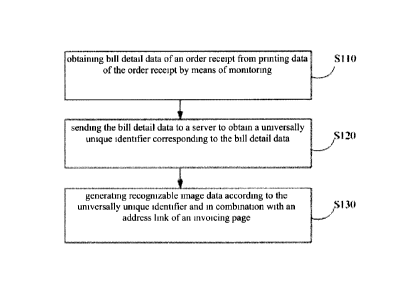
[0034] FIG. 1 is a flow chart of a printing data processing method provided
in an
embodiment of the present disclosure.
[0035] FIG. 2 is a flow chart of step S110 in FIG. 1 in an embodiment of
the present
disclosure.
[0036] FIG. 3 is a schematic diagram of driver printing in an embodiment of
the present
disclosure.
[0037] FIG. 4 is a schematic diagram of obtaining bill detail data based on
a mode of driver
printing in an embodiment of the present disclosure.
[0038] FIG. 5 is a schematic diagram of an SPL file during driver printing
in an embodiment
of the present disclosure.
[0039] FIG. 6 is a schematic diagram after an SPL file is parsed during
driver printing to
obtain bill detail data in a text form in an embodiment of the present
disclosure.
4
CA 3060951 2019-11-06
[0040] FIG. 7 is a schematic diagram of port printing in an embodiment of
the present
disclosure.
[0041] FIG. 8 is a schematic diagram of obtaining bill detail data based on
a mode of port
printing in an embodiment of the present disclosure.
[0042] FIG. 9 is a schematic diagram of instruction data obtained from port
monitoring
during port printing in an embodiment of the present disclosure.
[0043] FIG. 10 is a schematic diagram after instruction data of port
printing is parsed during
port printing to obtain bill detail data in a text form in an embodiment of
the present disclosure.
[0044] FIG. 11 is a flow chart of a printing data processing method in an
embodiment of the
present disclosure by taking an order receipt printed by cashier software to
obtain an QR code
image as an example.
[0045] FIG. 12 is a flow chart of an electronic invoice generating method
provided in
another embodiment of the present disclosure.
[0046] FIG. 13 is a flow chart of an electronic invoice issuing method in
another
embodiment of the present disclosure by taking user's filling in an invoice
title as an example.
[0047] FIG. 14 is a schematic diagram of a printing data processing
apparatus provided in
another embodiment of the present disclosure.
[0048] FIG. 15 is a schematic diagram of a server provided in another
embodiment of the
present disclosure.
[0049] FIG. 16 is a structural schematic diagram of an electronic device
provided in an
embodiment of the present disclosure and suitable to achieve embodiments of
the present
application.
DETAILED DESCRIPTION
[0050] Now, exemplary implementation manners are more comprehensively
described with
reference to accompanying drawings. However, exemplary implementation manners
can be
implemented in various forms and should not be understood that they are
limited to the examples
set forth herein; on the contrary, provision of these implementation manners
makes the present
disclosure more comprehensive and complete and comprehensively conveys the
conception of
the exemplary implementation manners to those skilled in the art. The
accompanying drawings
are only schematic diagrams of the present disclosure and not drawn definitely
in proportion. The
CA 3060951 2019-11-06
same reference signs in the drawings denote the same or similar parts, so the
repetitive
description on them will be omitted here.
[0051] Further, the described characteristics, structures or features can
be combined in one
or more implementation manners in any appropriate way. In the following
description, many
details are provided to fully understand the implementation manners of the
present disclosure.
However, those skilled in the art will be aware that the technical solution of
the present
disclosure can be practiced while omitting one or more of the specific
details, or other methods,
components, apparatuses and steps can be adopted. Under other circumstances,
well-known
structures, methods, apparatuses, realizations, materials or operations are
not stated or described
in detail to avoid stealing the show and blur various aspects of the present
disclosure.
[0052] Some block diagrams shown in the accompanying drawings are
functional entities
and do not have to correspond to physically or logically independent entities.
These functional
entities can be achieved in form of software, or in one or more hardware
modules or integrated
circuits, or in different networks and/or processor devices and /or
microprocessor devices.
[0053] In order to make the objectives, technical solutions and advantages
of the present
invention clearer and more comprehensible, the present invention is further
elaborated in
combination with specific embodiments and with reference to accompanying
drawings.
[0054] In relevant embodiments of the present invention, if cashier
software also needs to
possess a function of supporting issuance of electronic invoices, the original
cashier software can
be upgraded. By connecting an electronic invoice system to submit bill
details, the upgraded
cashier software can support issuance of electronic invoices. However, the
upgrading of the
original cashier software is costly. Many small and medium enterprises use
third-party cashier
software. If they want support to issuance of electronic invoices, they need
to obtain consent of
cashier software before they can implement the upgrading. Moreover, upgrading
of the existing
business system is labor and time consuming.
[0055] Further, a system that can not only connect cashier software to
obtain bill details but
also connect an electronic invoice system to issue electronic invoices can be
developed
additionally, but this system needs to connect cashier software to obtain
purchase details, and
there are numerous brands of cashier software, imposing a great difficulty in
connection. As the
business reformation schemes are diverse, subsequent reformation for new
requirements will be
troublesome and no unified solution can be provided.
6
CA 3060951 2019-11-06
[0056] Neither of the above two schemes provides a general solution for
fast issuance of an
electronic invoice. Some embodiments of the present disclosure provide a
printing data
processing method and apparatus, an electronic invoice generating method and a
server as well
as an electronic device and a computer readable medium to which the printing
data processing
method and the electronic invoice generating method correspond.
[0057] FIG. 1 is a flow chart of a printing data processing method provided
in an
embodiment of the present disclosure, comprising the following steps:
[0058] As shown in FIG. 1, at step S110, obtaining bill detail data of an
order receipt from
printing data of the order receipt by means of monitoring.
[0059] As shown in FIG. 1, at step S120, sending the bill detail data to a
server to obtain a
universally unique identifier corresponding to the bill detail data.
[0060] As shown in FIG. 1, at step S130, generating recognizable image data
according to
the universally unique identifier and in combination with an address link of
an invoicing page.
[0061] The printing data processing method in this exemplary embodiment
obtains bill
detail data from printing data by means of monitoring and then may generate a
corresponding
address link according to a universally unique identifier and an invoicing
page to which the bill
detail data corresponds, and present the address link to a user in form of
recognizable image data.
By packaging the bill detail data and the invoicing page into a special link,
a universal solution
for issuance of electronic invoices can be provided under the precondition of
not upgrading
cashier software and not specially developing middleware connecting various
kinds of cashier
software and invoicing systems, thereby reducing development cost and
maintenance cost.
[0062] Below, all steps of the printing data processing method in the
embodiment of the
present disclosure will be described further.
[0063] At step S110, obtaining bill detail data of an order receipt from
printing data of the
order receipt by means of monitoring.
[0064] In an embodiment of the present disclosure, an order receipt is a
consumption
voucher printed by merchant's cashier register after shopping or consumption
of a user. In
general, an order receipt contains the following content: seller name, contact
way, cashier
register number, bill serial number, cashier number, sales date, goods name,
quantity, unit price,
goods amount, total amount, payment method, paid-in amount, amount of change,
bill printing
time, etc. The printing data in this embodiment particularly refers to goods
name, quantity, unit
7
CA 3060951 2019-11-06
price, goods amount, total amount and other detail data relevant to invoicing
and does not
include cashier register number, bill serial number, cashier number and other
information
irrelevant to invoicing.
[0065] FIG. 2 shows a flow chart of step S110 in FIG. 1, comprising the
following steps:
[0066] As shown in FIG. 2, at step S201, converting printing data of an
order receipt into an
instruction file, wherein the instruction file contains data that can be
received and recognized by
a printer.
[0067] As shown in FIG. 2, at step S202, monitoring the instruction file by
means of
monitoring.
[0068] As shown in FIG. 2, at step S203, parsing the monitored instruction
file to obtain bill
detail data to which the printing data corresponds.
[0069] In an embodiment of the present disclosure, parsing the monitored
instruction file to
obtain bill detail data at step S203 specifically comprises: parsing printing
instructions in the
monitored instruction file through a printer instruction set to obtain bill
detail data to which the
printing data corresponds, to be specific:
[0070] judging if the designated file is a text or an image, and if the
instruction file is a text,
then parsing printing instructions in the monitored instruction file through a
printer instruction
set to obtain bill detail data to which the printing data corresponds; if the
instruction file is an
image, then performing OCR recognition of the image to obtain a text to which
the image
corresponds and parsing the text to which the image corresponds through a
printer instruction set,
i.e., parsing the text after image conversion through an instruction set to
obtain bill detail data to
which the printing data corresponds and to avoid garbling, omission of bill
detail data obtained
by means of monitoring printing data, and wrong information in the issued
invoices.
[0071] After bill detail data is obtained, the following setting can be
adopted to save parsed
bill detail data:
[0072] In Printer ->Printer attribute -> Advanced, tick a printed file to
save it.
[0073] In addition to issuing an invoice, a saved file can also be used for
other purposes. For
example, the saved file contains bill details, which can be saved in a format
of text or table or
can be sent to a file designated by a user so that the user conducts
electronic bookkeeping.
[0074] In an embodiment of the present disclosure, the means of monitoring
include:
monitoring application layer data or driver layer data of client-side cashier
software through port
8
CA 3060951 2019-11-06
monitoring. The printer prints data mainly in two modes, including driver
printing and port
printing. Accordingly, the processes of monitoring printing data are
different, too. Below they are
introduced separately:
[0075] FIG. 3 is a schematic diagram of driver printing. As shown in FIG.
3, driver printing
relates to application programs (such as cashier software, etc.) installed on
the client side (such
as a computer), a printing driver installed on the client side and a printer
connected to the client
side in form of communication. The communication connection can be wired
connection or
wireless connection. The principle of driver printing is that the client side
converts printing data
via a drive program into an EMF file (Enhanced Meta File) that can be
recognized and printed by
a printer, and sends the EMF file to a printer for printing. In the process of
printing, a GDI
(Graphics Device Interface) module performs basic data exchange with a
printing driver
(provided by the printer manufacturer in general) to generate printer command
files: SPL file and
SHD file. Printing data is mainly included in the SPL file, while information
describing which
printer the printing data is sent to, via which port the printing data is sent
and at what baud rate
the printing data is sent is included in SHD data. Data in the SPL file is in
a format of EMF, i.e.,
is EMF data. Then (Windows for example) printing thread processes the printing
operation (i.e.,
data is printed one by one), the SPL file is transmitted to the printer for
printing according to the
description information in SHD, and the file of the printing data is deleted
after the printing is
completed. Further, in addition to a GDI module, which converts printing data
from the client
side into an SPL file in a format of EMF, the printing driver in this
embodiment also includes a
format conversion module (GDI/DDI driver for example is a data recovery
mirroring tool),
which is used to parse the SPL file to obtain bill detail data in a text form.
[0076] FIG. 4 is a schematic diagram of obtaining bill detail data based on
a mode of driver
printing. As shown in FIG. 4, firstly, the GDI module processes printing data
into an SPL file.
FIG. 5 is a schematic diagram of an SPL file during driver printing. Then, the
SPL file is
obtained by means of monitoring and parsed to obtain data in a format of EMF.
The monitored
and intercepted SPL file is not plaintext data (visualized data). The data in
a format of EMF in
the SPL file needs to be parsed into plaintext data, i.e., bill detail data in
a text form. FIG. 6 is a
schematic diagram after an SPL file is parsed during driver printing to obtain
bill detail data in a
text form.
[0077] Below, a processing method in a parsing process is introduced:
9
CA 3060951 2019-11-06
[0078] Firstly, EMF mainly comprises EMF header record, description and
record.
[0079] (1) The structure of the EMF header record is as follows:
typedef struct tagENHMETAHEADER
{
DWORD iType; it should be 1 (EMR_HEADER)
DWORD nSize; Header size, not including description
[0080] RECTL rclBounds; image frame size (device unit)
RECTL rclFrame; image frame size (0.01 mm is a unit)
DWORD dSignature; 0x464d4520 (EMF tag)
1
[0081] This structure describes the type of sorted record, data size, image
data toning
position and other relevant data attributes. Through this structure, detailed
information of the
record can be obtained, and data can be parsed.
[0082] (2) EMF description:
[0083] If nDescription of the header record is greater than 0, it means
there is content, and
otherwise it means it is empty. Generally, it is immediately behind
EMR_HEADER.
[0084] (3) EMF record:
[0085] iType; type, such as EMR_HEADER, EMR_EOF. All the parsed data are
among
these types. Through type judgment, we can know types of these data. These
data are all between
EMR_HEADER and EMR_EOF, these two types.
[0086] Example: EMR_HEADER data starting record.
[0087] Data behind EMR_EXTTEXTOUTA is plaintext and can be outputted
directly.
[0088] Data behind EMR_STRETCHDIBITS and EMR SETDIBITSTODEVICE is image
data.
[0089] EMR_EOF data ending record.
[0090] After analysis and processing of the above records, printer data can
be obtained.
[0091] As data in a format of EMF includes text data and image data, the
image data also
needs to be subjected to OCR image parsing to generate plaintext, obtain text
data and eventually
obtain text data after SPL parsing to facilitate subsequent corresponding
applications, such as an
intelligent invoicing system, and printing of an added QR code on an order
receipt.
CA 3060951 2019-11-06
[0092] FIG. 7 is a schematic diagram of port printing. As shown in FIG. 7,
port printing
relates to application programs (such as cashier software, etc.) installed on
the client side (such
as a computer) and a printer connected to the client side in form of
communication. Ports in port
printing include without limitation: serial port, parallel port, Ethernet port
and USB port. The
principle of port printing is to convert printing data (in a text form) sent
by an application
program on the client side into instruction data, and then send the
instruction data via a port to a
printer and print it. Port printing does not need a driver program.
[0093] Based on the above description, in a mode of port printing, printing
data needs to be
obtained by means of port monitoring.
[0094] FIG. 8 is a schematic diagram of obtaining bill detail data based on
a mode of port
printing. As shown in FIG. 8, firstly, a printing port is monitored in a
driver layer to obtain
instruction data converted from printing data. FIG. 9 is a schematic diagram
of instruction data
obtained from port monitoring during port printing. Secondly, after the
instruction data is
obtained, the instruction data is submitted to an application layer, the
application layer performs
instruction parsing of the instruction data, and conducts parsing in
combination with an
instruction set after OCR recognition or directly in combination with an
instruction set to obtain
bill detail data in a text form. FIG. 10 is a schematic diagram after
instruction data of port
printing is parsed during port printing to obtain bill detail data in a text
form
[0095] In an embodiment of the present disclosure, printing data is
converted into
instruction data during port printing. This instruction data is recognizable
to printers. That is, a
client-side computer controls printer operation through a printing control
language by the method
of software commands, interpretively executes printing data and obtains a
printing result. As far
as complex functions achieved by a printer are concerned, a printing control
language is a
foundation, which has a direct bearing on quality of printing input.
[0096] Currently, there are three mainstream printer control languages:
[0097] (1) ESC command set of Epson: The ESC command set is a de facto
industrial
standard in the fields of needle printers and bill printing;
[0098] (2) PCL command set of HP: The PCL command set is an industrial
standard in the
fields of low-end laser printers and ink printers;
[0099] (3) PostScript ("PS" for short) command set of Adobe: The PS command
set is a
page description language assuming a monopoly position in the field of high-
end typesetting.
11
CA 3060951 2019-11-06
[0100] When printing order receipts, cashier software typically uses an ESC
instruction set.
There are two formats of ESC instructions: text mode control codes and Escape
sequence codes.
A text mode control code is expressed with a single-byte character code and
achieves an
instruction relevant to operation of printer hardware. An Escape sequence code
comprises an
Escape character and a parameter character or printing data.
[0101] EPSON ESC/POS control commands are as follows:
[0102] Commands in an English mode are shown in Table 1:
[0103]
Code Function Code Function
LF Line feed ESC m Local cutting
CR Carriage return ESC o Seal
ESC SP Set a right margin ESC q Release paper
ESC! Set a printing mode ESC r Select a printing color
ESC Set a bit-mapping mode ESC z Set or cancel parallel printing
of
two pages
ESC @ Initialize the printer ESC Buzzer ON/OFF
BEL
ESC R Select an international character ESC c5 Disable/enable the panel
switch
subset
ESC d Print and Line N feed ESC c6 Disable/enable the ON-LINE
switch
,
ESC t Select a character code table ESC p Generate a designated
pulse
ESC 1 Select or cancel inverted ESC V Send a printer state
characters
ESC c0 Select a printing page ESC ¨ LED ON/OFF
FF Print out a leaflet HT Horizontal TAB
RS Running TAB ESC % Select or cancel a user-defined
character set
ESC 2 Select a line space of 1/6 inches ESC & .. Define a user-defined
character
set
12
CA 3060951 2019-11-06
ESC 3 Set line width as the minimum ESC D Set a TAB position
space
ESC < Go back to the beginning of line ESC i Full cutting
ESC C Set leaflet length ESC f Set a leaflet wait time
ESC F Select or cancel the back paper ESC e Print and return to
line N
area of the leaflet
[0104]
ESC J Print and feed in a minimum ESC c4 Select printing paper and
detector
space (end printing)
ESC K Print and feed in a minimum ESC c3 Select paper end signal output
space
ESC U Select or cancel one-way ESC cl Select a line space
printing
[0105] Table 1
[0106] The commands in a Chinese mode are as shown in Table 2:
[0107]
Code Function Code Function
FS & Select a Chinese character FS-n Set a Chinese character underline
mode mode switch
FS Cancel the Chinese mode FS ! n Select a Chinese font
[0108] Table 2
[0109] At step S120, sending the bill detail data to a server to obtain a
universally unique
identifier corresponding to the bill detail data.
[0110] UUID (Universally Unique Identifier) means that it guarantees
numbers generated on
a machine are unique to all machines in the same time and space. Typically,
the platform will
provide generated API. UUID is calculated according to a standard formulated
by the Open
Software Foundation (OSF) and used in Ethernet card addresses, nanosecond
time, chip ID codes
and many other possible numbers.
[0111] UUID comprises the following few parts:
[0112] (1) Present date and time: The first part of UUID is relevant to
time. If one more
UUID is generated a few seconds after generation of a UUID, they are different
in the first part
13
CA 3060951 2019-11-06
and same in rest parts.
[0113] (2) Clock sequence.
[0114] (3) Globally unique IEEE machine identification number: It is
obtained from a
network card MAC address if there is a network card, or obtained by other
methods if there is
not a network card.
[0115] At step Si 30, generating recognizable image data according to the
universally unique
identifier and in combination with an address link of an invoicing page.
[0116] In an embodiment of the present disclosure, the recognizable image
data is a QR
code image. Generating recognizable image data according to the universally
unique identifier
and in combination with an address link of an invoicing page comprises:
[0117] encoding the address link and the universally unique identifier by
an encoding
method for QR codes to obtain the QR code image. This step mainly packages an
UUID
containing bill detail data and an address link of the invoicing page to
obtain recognizable data in
a packaged form.
[0118] Next, FIG. 11 is a flow chart of a printing data processing method
by taking an order
receipt printed by cashier software to obtain an QR code image as an example.
As shown in FIG.
11, this process relates to client-side cashier software, a client plug-in, a
printer and a server and
comprises the following steps:
[0119] Step S1101, cashier software obtains printing data of an order
receipt.
[0120] Step S1102, the cashier software sends the printing data to a
printer for printing. The
printing data contains bill detail data and exists in form of an SPL file or
instruction data.
[0121] Step S1103, the client plug-in monitors through printing data sent
to a printer by a
cashier system, and parses the monitored SPL file or instruction data into
bill detail data in a text
form, i.e., receipt details.
[0122] Step S1104, the client plug-in uploads the receipt details to a
server.
[0123] Step S1105, the server converts the receipt details into a
corresponding receipt detail
UUID and returns it to the client plug-in.
[0124] Step S1106, the client plug-in generates a QR code image according
to the receipt
detail UUID and an address link of an invoicing page.
[0125] Step S1107, the client plug-in sends the QR code image to a printer
for printing.
[0126] To sum up, the printing data processing method provided in this
embodiment obtains
14
CA 3060951 2019-11-06
bill detail data from printing data by means of monitoring and then may
generate a
corresponding address link according to a universally unique identifier and an
invoicing page to
which the bill detail data corresponds, and present the address link to a user
in form of
recognizable image data. By packaging the bill detail data and the invoicing
page into a special
link, a universal solution for issuance of electronic invoices can be provided
under the
precondition of not upgrading cashier software and not specially developing
middleware
connecting various kinds of cashier software and invoicing systems. The
printing data processing
method is suitable for clients of most systems (Windows system) without
connecting or
transforming the existing ERP system, thereby reducing development cost and
maintenance cost.
[0127] Based on the foregoing printing data processing method for order
receipts, the
present disclosure further provides an electronic invoice generating method.
FIG. 12 is a flow
chart of an electronic invoice generating method provided in another
embodiment of the present
disclosure, comprising the following steps:
[0128] As shown in FIG. 12, at step S1210, recognizing recognizable image
data to obtain
an address link, and presenting the invoicing page to a user via the address
link, which contains a
universally unique identifier of an order receipt and an invoicing page.
[0129] As shown in FIG. 12, at step S1220, obtaining user information of an
invoice at the
invoicing page.
[0130] As shown in FIG. 12, at step S1230, submitting an invoicing request
to an invoice
platform according to the user information and the universally unique
identifier, and obtaining an
electronic invoice returned by the invoice platform in response to the
invoicing request.
[0131] By the electronic invoice generating method provided in this
exemplary embodiment,
when a user needs to issue an electronic invoice, the user only needs to scan
the QR code to enter
a specific page. As the special link provided to the user during invoicing
contains bill detail data,
after providing user information needed for invoicing, the user can submit an
invoicing request
and have an electronic invoice containing bill detail data issued, thereby
simplifying operations
of the user and the merchant, raising invoicing speed and improving user
experience. Further,
invoices are no longer issued by category but by details, conforming to
relevant provisions.
[0132] Below, all steps of the electronic invoice issuing method in the
embodiment of the
present disclosure will be further described.
[0133] At step S1210, recognizing recognizable image data to obtain an
address link, and
CA 3060951 2019-11-06
presenting the invoicing page to a user via the address link, which contains a
universally unique
identifier of an order receipt and an invoicing page.
[0134] In an embodiment of the present disclosure, before obtaining a
universally unique
identifier of an order receipt, step S1210 further comprises:
[0135] obtaining bill detail data of the order receipt, wherein the method
for obtaining bill
detail data according to a printed order receipt is as described in foregoing
embodiments and is
not described again here;
[0136] generating a universally unique identifier of the order receipt
according to the bill
detail data.
[0137] In an embodiment of the present disclosure, after obtaining a
universally unique
identifier of an order receipt, step S1210 further comprises:
[0138] parsing the universally unique identifier to obtain bill detail data
of the order receipt,
wherein the invoicing page presented to a user contains the bill detail data.
[0139] In an embodiment of the present disclosure, recognizable image data
is a QR code
image, and a user can invoke a QR code recognition program of a mobile
terminal, scan the QR
code image and jump to an invoicing page according to the address link. It
needs to be explained
that after parsing, a QR code is not only an address link, and the opened page
also contains a
receipt detail UUID that has been packaged in the QR code, in other words, the
page has
contained bill detail data, so the user does not need to input details any
more.
[0140] It needs to be explained that the page entered at this step is a
popular H5 page in the
industry as an example, but no limitation is set to page types.
[0141] As shown in FIG. 12, at step S1220, obtaining user information of an
invoice at the
invoicing page.
[0142] In an embodiment of the present disclosure, the user information
contains at least: an
invoice title and an identification number. At an invoicing page, a user can
complete information
entry of invoicing by only inputting an invoice title, an identification
number and other relevant
information.
[0143] As shown in FIG. 12, at step S1230, submitting an invoicing request
to an invoice
platform according to the user information and the universally unique
identifier, and obtaining an
electronic invoice returned by the invoice platform in response to the
invoicing request.
[0144] Next, FIG. 13 is a flow chart of an electronic invoice issuing
method by taking user's
16
CA 3060951 2019-11-06
filling in an invoice title as an example. As shown in FIG. 13, this process
relates to a mobile
terminal, a server and an invoice platform, and comprises the following steps:
[0145] Step S1301, a user scans a QR code by a mobile terminal and requests
for an invoice
title H5 page to a server.
[0146] Step S1302, the server returns the invoice title H5 page and a
receipt detail UUID to
the mobile terminal.
[0147] Step S1303, the user inputs an invoice title at an invoice title H5
page presented on
the mobile terminal, and submits an invoicing request to the server.
[0148] Step S1304, the mobile terminal sends the invoice title and the
receipt detail UUID to
the server.
[0149] Step S1305, the server sends an electronic invoice issuing request
to an invoice
platform.
[0150] Step S1306, the invoice platform generates an electronic invoice and
returns the
electronic invoice to the server.
[0151] Step S1307, the server sends the electronic invoice to the user in a
way designated by
the user, for example, the server may send the electronic invoice to a mailbox
reserved by the
user.
[0152] To sum up, by the electronic invoice issuing method provided in this
embodiment,
when a user needs to issue an electronic invoice, the user only needs to scan
the QR code to enter
a specific page. As the special link provided to the user during invoicing
contains bill detail data,
after providing user information needed for invoicing, the user can submit an
invoicing request
and have an electronic invoice containing bill detail data issued, thereby
simplifying operations
of the user and the merchant, raising invoicing speed and improving user
experience. Further,
invoices are no longer issued by category but by details, conforming to
relevant provisions.
[0153] FIG. 14 is a schematic diagram of a printing data processing
apparatus provided in
another embodiment of the present disclosure. As shown in FIG. 14, the
apparatus 1400
comprises: a detail obtaining module 1410, an identification code obtaining
module 1420 and an
image generating module1430.
[0154] The detail obtaining module 1410 is configured to obtain bill detail
data of an order
receipt from printing data of the order receipt by means of monitoring; the
identification code
obtaining module 1420 is configured to send the bill detail data to a server
to obtain a universally
17
CA 3060951 2019-11-06
unique identifier corresponding to the bill detail data; the image generating
module 1430 is
configured to generate recognizable image data according to the universally
unique identifier and
in combination with an address link of an invoicing page.
[0155] The printing data processing apparatus can be a plug-in installed on
the client side so
as to monitor printing data sent from the client side to a printer, thereby
parsing and obtaining
bill detail data. The bill detail data not only can be used to issue an
invoice but also can be used
in more scenarios such as electronic bookkeeping. Functions of modules in this
apparatus are
shown in relevant description in the foregoing embodiment of a printing data
processing method
and are not described again.
[0156] FIG. 15 is a schematic diagram of a server provided in another
embodiment of the
present disclosure. As shown in FIG. 15, a user of the server achieves
issuance of an electronic
invoice. The server 1500 comprises: a page presenting module 1510, an
information obtaining
module 1520 and an invoicing module 1530.
[0157] The page presenting module 1510 is configured to recognize
recognizable image data
to obtain an address link, and present the invoicing page to a user via the
address link, which
contains a universally unique identifier of an order receipt and an invoicing
page; the information
obtaining module 1520 is configured to obtain user information of an invoice
at the invoicing
page; and the invoicing module 1530 is configured to submit an invoicing
request to an invoice
platform according to the user information and the universally unique
identifier, and obtain an
electronic invoice returned by the invoice platform in response to the
invoicing request.
[0158] This server is the server shown in the above diagram. Functions of
modules in this
server are shown in relevant description in the foregoing embodiment of an
electronic invoice
issuing method and are not described again.
[0159] On the other hand, the present disclosure further provides an
electronic device,
comprising a processor and a memory, storing instructions for controlling
steps of the following
method by the foregoing processor:
[0160] obtaining bill detail data of an order receipt from printing data of
the order receipt by
means of monitoring; sending the bill detail data to a server to obtain a
universally unique
identifier corresponding to the bill detail data; and generating recognizable
image data according
to the universally unique identifier and in combination with an address link
of an invoicing page.
Or
18
CA 3060951 2019-11-06
[0161] recognizing recognizable image data to obtain an address link, and
presenting the
invoicing page to a user via the address link, which contains a universally
unique identifier of an
order receipt and an invoicing page; obtaining user information of an invoice
at the invoicing
page; submitting an invoicing request to an invoice platform according to the
user information
and the universally unique identifier, and obtaining an electronic invoice
returned by the invoice
platform in response to the invoicing request
[0162] Below FIG. 16 is referred to. FIG. 16 is a structural schematic
diagram of a computer
system 1600 of an electronic device suitable to achieve embodiments of the
present application.
FIG. 16 shows only an example of an electronic device and should not impose
any restriction on
functions and use scope of embodiments of the present application.
[0163] As shown in FIG. 16, the computer system 1600 comprises a central
processing unit
(CPU) 1601, which can execute various appropriate actions and processing
according to
programs stored in a read only memory (ROM) 1602 or programs loaded from a
storage unit
1606 to a random access memory (RAM) 1603. The RAM 1603 also stores all kinds
of programs
and data that operation of the system 1600 needs. The CPU 1601, ROM 1602 and
RAM 1603 are
mutually connected via a bus 1604. An input/output (I/0) interface 1605 is
also connected to the
bus 1604.
[0164] The following components are connected to the I/0 interface 1605: an
input unit
1606 comprising a keyboard, a mouse, etc.; an output unit 1608 comprising for
example a
cathode ray tube (CRT), a liquid crystal display (LCD), a loudspeaker, etc.; a
storage unit 1608
comprising a hard disk, etc.; as well as a communication unit 1609 comprising
for example an
LAN card, Modem and other network interface cards. The communication unit 1609
performs
communication processing via a network such as the Internet. The driver 1610
is also connected
to the I/0 interface 1605 according to the need. A detachable medium 1611,
such as magnetic
disk, optical disk, magnetic optical disc and semiconductor memory, is
installed on the driver
1610 according to the need so that computer programs read from the detachable
medium 1611
are installed and saved in the storage unit 1608 as needed.
[0165] Specially, according to embodiments of the present disclosure, the
process described
with reference to a flow chart in the preceding part of the text can be
achieved as a computer
software program. For example, an embodiment of the present disclosure
includes a computer
program product, comprising a computer program loaded on a computer readable
medium. This
19
CA 3060951 2019-11-06
computer program contains a program code used to implement the method shown in
the flow
chart. In such embodiment, this computer program can be downloaded and
installed from the
network via the communication unit 1609, and/or installed from the detachable
medium 1611.
When this computer program is executed by the CPU 1601, the foregoing
functions defined in
the system of the present application are executed.
[0166] It needs to be explained that the computer readable medium shown in
the present
application can be a computer readable signal medium or a computer readable
medium or any
combination of the foregoing two. The computer readable medium for example can
be ¨ without
limitation ¨ an electric, magnetic, optical, electromagnetic, infrared or
semiconductor system,
apparatus or device, or any combination thereof. More concrete examples of the
readable
memory media may include without limitation: electric connection with one or
more conductors,
portable computer magnetic disk, hard disk, random access memory (RAM), read
only memory
(ROM), erasable programmable read-only memory (EPROM or flash memory), optical
fiber,
portable compact disk read only memory (CD-ROM), optical memory module,
magnetic
memory module or any appropriate combination thereof In the present
application, a readable
memory medium can be any tangible medium containing or storing programs, which
can be used
by an instruction execution system, apparatus or device or can be used in
combination with an
instruction execution system, apparatus or device. In the present application,
computer readable
signal media may include data signals transmitted in base band or as part of
carriers, and carry
computer readable program codes. Such transmitted data signals can adopt
various forms,
including but not limited to: electromagnetic signals, optical signals or any
appropriate
combination thereof The computer readable signal media may also be any
computer readable
media except readable memory media. Such computer readable media can send,
transmit or
transfer programs used by an instruction execution system, apparatus or device
or used in
combination with an instruction execution system, apparatus or device. The
program codes
contained on a computer readable medium can be transferred by any appropriate
medium,
including but not limited to: wireless, wired, optical cable and RF, or any
appropriate
combination thereof
[0167] The flow charts and block diagrams in the accompanying drawings show
system
architectures, functions and operations likely achieved according to the
systems, methods and
computer program products of various embodiments of the present application.
At this point,
CA 3060951 2019-11-06
every box in the flow charts or block diagrams can represent a part of a
module, a program
segment or a code. The foregoing part of a module, a program segment or a code
comprises one
or more executable instructions used to achieve a specified logical function.
It should also be
noted that in the realization of some replacements, functions marked in boxes
may also occur in
a sequence different from that marked in the accompanying drawings. For
example, two boxes
expressed successively can be executed basically in parallel in fact, and
sometimes, they can be
executed in a reverse sequence, depending on involved functions. It should
also be noted that
each box in block diagrams or flow charts and combinations of boxes in the
block diagrams or
flow charts can be achieved using a special hardware-based system that
executes specified
functions, or can be achieved using a combination of special hardware and
computer
instructions.
[0168] Description of units involved in embodiments of the present
application can be
achieved in form of software, or in form of hardware. The described units may
also be arranged
in a processor. For example, it can be described as: a processor comprising a
sending unit, an
obtaining unit, a determining unit and a first processing unit. Names of these
units do not
constitute limitation to these units under some circumstances. For example,
the sending unit may
also be described as "a unit sending a picture obtaining request to a
connected server".
[0169] On the other hand, the present disclosure further provides a
computer readable
medium, which may be included in a device described in the foregoing
embodiments; or may
exist separately, and is not assembled into the device. The foregoing computer
readable medium
carries one or more programs. When the foregoing one or more programs are
executed by one of
such devices, the device includes the following method steps:
[0170] obtaining bill detail data of an order receipt from printing data of
the order receipt by
means of monitoring; sending the bill detail data to a server to obtain a
universally unique
identifier corresponding to the bill detail data; generating recognizable
image data according to
the universally unique identifier and in combination with an address link of
an invoicing page.
Or
[0171] recognizing recognizable image data to obtain an address link, and
presenting the
invoicing page to a user via the address link, which contains a universally
unique identifier of
an order receipt and an invoicing page; obtaining user information of an
invoice at the invoicing
page; and submitting an invoicing request to an invoice platform according to
the user
21
CA 3060951 2019-11-06
information and the universally unique identifier, and obtaining an electronic
invoice returned by
the invoice platform in response to the invoicing request.
[0172] It should be clearly understood that the present disclosure
describes how to form and
use specific examples, but the principles of the present disclosure are not
limited to any details of
these examples. On the contrary, based on teaching of the content disclosed by
the present
disclosure, these principles can be applied in many other implementation
manners.
[0173] Exemplary implementation manners of the present disclosure are
presented and
described above. It should be understood that the present disclosure is not
limited to the detailed
structures, setting modes or implementation methods described here; on the
contrary, the present
disclosure intends to cover all modifications and equivalent settings included
in the spirit and
scope of the claims.
22
CA 3060951 2019-11-06