Note: Descriptions are shown in the official language in which they were submitted.
METHOD AND APPARATUS FOR SULFUR FIRE-WATCH
AND DETECTION
FIELD OF THE INVENTION
[0001] This disclosure relates to a method and apparatus for detecting and
measuring sulfur
fires.
BACKGROUND
[0002] Typical sulfur storage sites contain large amounts of sulfur that may
be stored in large
blocks, pellets, or granule form. Some sulfur may be stored in large
stockpiles either
outdoors or within warehouses, where the stockpiles may have a size that could
be
over 30 meters high and approximately 300 meters long and approximately 200
meters wide. In fact, some of the sulfur facilities may have an area of
greater than
0.25 square kilometers. One of the bigger dangers at these storage sites is
the risk of
fire, as sulfur is combustible and when burned gives off a toxic gas, sulfur
dioxide
(SO2), which is an irritant to a person's lungs in low concentrations and
could be toxic
or life threatening the concentrations are high. Thus, any fire detection
system would
help a storage site comply with appropriate safety regulations set forth by
Occupational Safety and Health Administration (OSHA) or The National Institute
for
Occupational Safety and Health (NIOSH). Sulfur
dioxide also poses an
environmental threat as being a contributor to acid rain.
[0003] When sulfur burns it typically has a bluish or violet colored flame,
which can be
missed by the human eye in the visible light spectrum. In addition, sulfur
dioxide is a
colorless gas that can also be missed by the human eye making its detection
difficult.
Further, since sulfur burns at a temperature lower than wood or hydrocarbons,
a sulfur
fire may not be easily detected. At present, sulfur fire-watch and detection
is done by
a person who is physically on site, where he or she may detect a sulfur fire
by the
distinct smell given off by the sulfur dioxide.
BRIEF SUMMARY
[0004] The following presents a general summary of aspects of the disclosure
in order to
provide a basic understanding of the disclosure. This summary is not an
extensive
11924901-1 1
CA 3061250 2019-11-12
overview of the disclosure. It is not intended to identify key or critical
elements of
the disclosure or to delineate the scope of the disclosure. The following
summary
merely presents some concepts of the disclosure in a general form as a prelude
to the
more detailed description provided below.
[0005] Aspects of this disclosure may relate to a system for detecting sulfur
fires in a sulfur
stockpile that include a sensor located a predetermined distance from the
sulfur
stockpile, wherein the sensor may have a field of view of the sulfur
stockpile. The
sensor may be configured to receive radiation emitted from the sulfur
stockpile. The
system may also include a processor configured to receive data from the
sensor, and
where upon receiving data from the sensor, the processor may determine if an
amount
of sulfur dioxide gas is greater than a predetermined limit of sulfur dioxide
gas. If the
processor determines the amount of sulfur dioxide gas is greater than the
predetermined limit, the processor may send a signal to an alarm. The sensor
may .be
capable of receiving electromagnetic radiation within a range of 1 gm
wavelength and
16 m. In some embodiments, the sensor may be an infrared sensor. The
predetermined limit of the amount of sulfur dioxide gas may be a slant column
density
of a sulfur plume with a path concentration above about 1,000 ppm-m. In
addition,
the predetermined distance from the sulfur stockpile may be within 5000 meters
of the
sulfur stockpile. In some instances, the sensor may actually comprise three
sensors
evenly spaced apart from each other around the sulfur stockpile. The sensor
may also
be configured to move the field of view of the sensor in a predetermined scan
schedule, where the predetermined scan schedule may be a range height
indicator
scan using a fixed azimuth angle while varying an elevation angle.
Additionally, the
system may transmit the signal wirelessly to a remote computer. In other
embodiments, the sensor may be a microwave sensor. For instance, the sensor
may
be an active microwave sensor, where the active microwave sensor detects
radiation
that is emitted by the sulfur stockpile and other objects within the field of
view, or the
sensor may be a passive sensor, where the passive microwave sensor detects
radiation
that is emitted or reflected by the sulfur stockpile and other objects within
the field of
view.
[0006] Still other aspects of this disclosure may relate to a system for
detecting sulfur fires in
a sulfur stockpile that include an infrared sensor located a predetermined
distance
11924901-1 2
CA 3061250 2019-11-12
from the sulfur stockpile, where the infrared sensor has a field of view of
the sulfur
stockpile and is configured to receive radiation emitted from the sulfur
stockpile. The
system may also include a processor configured to receive data from the
infrared
sensor, and a non-transitory, computer-readable medium storing computer-
executable
instructions that, when executed by the processor, causes the processor to at
least: (1)
receive data from the infrared sensor; (2) determine using thermal contrast
imaging if
sulfur dioxide is present in the field of view; (3) calculate a slant column
density of a
sulfur plume; (4) compare the calculated slant column density to a
predetermined
limit; and (5) send a signal to an alarm if the calculated slant column
density is greater
than a predetermined limit of sulfur dioxide gas. The system may have a
predetermined limit of sulfur dioxide gas is at a path concentration above
about 1,000
ppm-m, and the system may be set at a predetermined distance from the sulfur
stockpile is within 5000 meters of the sulfur stockpile. In addition, the
sensor may be
three sensors that are evenly spaced apart from each other around the sulfur
stockpile.
The sensor may be connected to a mount that is configured to move the sensor
such
that the field of view of the sensor moves in a predetermined scan schedule.
[0007] Yet other aspects of this disclosure may relate to a system for
detecting sulfur fires in
a sulfur stockpile an infrared sensor located a predetermined distance from
the sulfur
stockpile, where the infrared sensor has a field of view of the sulfur
stockpile and is
configured to receive radiation emitted from the sulfur stockpile. The system
may
also include a processor configured to receive data from the infrared sensor
and a non-
transitory, computer-readable medium storing computer-executable instructions
that,
when executed by the processor, causes the processor to at least: (1) receive
data from
the infrared sensor; (2) determine a stockpile temperature of a portion of the
sulfur
stockpile within the field of view; (3) compare the stockpile temperature to a
predetermined threshold temperature, where upon determining that the stockpile
temperature is greater than the predetermined threshold temperature, send a
signal to
an alarm. The predetermined threshold temperature may be 190 Celsius. The
system
may further include a plurality of infrared sensors is evenly spaced apart
around the
sulfur stockpile.
BRIEF DESCRIPTION OF THE DRAWINGS
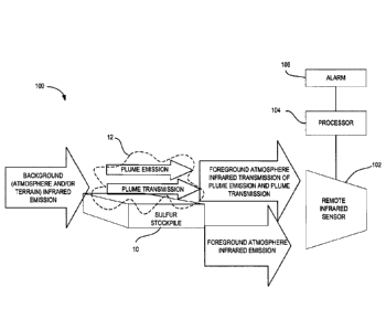
[0008] FIG. 1 is a schematic view of a system for detecting sulfur fires as
disclosed herein;
11924901-1 3
CA 3061250 2019-11-12
[0009] FIG. 2 is a flowchart of a method for detecting sulfur fires as
disclosed herein;
[0010] FIG. 3 is a schematic view of an alternate system for detecting sulfur
fires as
disclosed herein; and
[0011] FIG. 4 is a schematic view of an alternate system for detecting sulfur
fires as
disclosed herein.
DETAILED DESCRIPTION
[0012] In the following description of various example structures according to
the disclosure,
reference is made to the accompanying drawings, which form a part hereof, and
in
which are shown by way of illustration various example devices, systems, and
environments in which aspects of the disclosure may be practiced. It is to be
understood that other specific arrangements of parts, example devices,
systems, and
environments may be utilized and structural and functional modifications may
be
made without departing from the scope of the present disclosure. Nothing in
this
specification should be construed as requiring a specific three-dimensional
orientation
of structures in order to fall within the scope of this disclosure. The reader
is advised
that the attached drawings are not necessarily drawn to scale.
[0013] Generally, this disclosure relates to a method and system for
automating sulfur fire-
watch and sulfur fire detection. Thermal infrared remote sensing technologies
may be
used for the detection of emission plumes of atmospheric sulfur dioxide gas in
different environmental conditions that can provide data to determine the
source of
the plume. In more detail, the sulfur fire-watch and detection system 100 may
comprise a remote ground-based, airborne, or space-borne infrared sensor 102,
with a
thermal infrared imaging system that can detect sulfur dioxide gas to provide
for
unsupervised remote day and nighttime sulfur fire-watch, hot spot detection,
early
sulfur fire prevention, sulfur fire detection, and/or sulfur fire control of
unattended
combustible sulfur blocks, sulfur stockpiles, sulfur plants, or equipment
using remote
sensing devices that includes detection, measurement, and analysis of
electromagnetic
radiation to determine the presence of sulfur dioxide gas. The system 100 uses
a
source of electromagnetic radiation as electromagnetic radiation may penetrate
through the atmosphere, where the system 100 may measure and analyze the
electromagnetic radiation, digitize the analysis, transmit the data, and
signal an alarm
11924901-1 4
CA 3061250 2019-11-12
if a harmful condition is detected. In some embodiments, the system 100 may be
ground-based such as being mounted on a platform attached to the ground within
a
fixed distance from the Earth's surface. However, in some instances, infrared
sensors
may be mounted to an airborne system, like a drone or other aircraft, or in
some cases
asatellite, to monitor known sulfur stockpile locations to detect sulfur
dioxide gas.
[0014] FIG. 1 illustrates a schematic of an exemplary sulfur fire detection
system 100 for
remotely detecting a sulfur fire in a sulfur stockpile 10, where the sulfur
stockpile 10
may be an unattended sulfur block(s), a pile(s) of sulfur pellets or granules,
a sulfur
plant(s), sulfur processing equipment, or other large quantity of sulfur. The
fire
detection system 100 may comprise a remote infrared sensor 102 or a plurality
of
remote infrared sensors 102 that is/are positioned a predetermined distance
away from
the sulfur stockpile 10, but may have a generally uninterrupted field of view
of the
sulfur stockpile 10. The infrared sensor 102 may be able to operate during
both
daytime and nighttime to enable fire-watch control at all times. Infrared
sensors may
be preferred over a passive type ultraviolet (UV) sensor, as a UV sensor may
not
effectively function on a 24 hour basis since UV radiation is limited at
nighttime.
Generally, the infrared sensor 102 may receive the electromagnetic radiation
emitted
from the background atmosphere or terrain located behind the sulfur stockpile
10,
radiation emitted from the sulfur stockpile 10 within the storage area,
radiation
emitted from the foreground atmosphere and terrain, which is located between
the
sensor 102 and the sulfur stockpile 10, and any radiation emitted from a
sulfur fire or
sulfur plume 12 if present. As disclosed herein, the background terrain may
encompass all of the possible land-based radiation sources, such as the land
itself, any
buildings, or sulfur plant equipment that are present within the field of view
of the
sensor 102. The sensor 102 may include or be connected to a processor 104 that
may
convert the radiation received by the sensor 102 to an electronic signal that
may be
processed into numerical or image data. The data may then be further processed
to
detect the presence of sulfur dioxide gas (SO2) within the atmosphere captured
in its
field of view using thermal contrast imaging to determine the thermal contrast
between the background and sulfur dioxide gas. If the processor 104 determines
the
presence of sulfur dioxide gas, the processor 104 may send a signal to an
alarm 106
that is able to communicate via an audible alert, a visual alert, or some
other definitive
communication that a sulfur fire may be present. The alarm 106 may alert any
11924901-1 5
CA 3061250 2019-11-12
emergency personnel or responders to take the appropriate actions to address
the
situation, including extinguishing the fire.
[0015] As discussed above, when a sulfur fire is not present, the sensor 102
may receive
electromagnetic radiation emitted from the background atmosphere or terrain,
located
behind the sulfur dioxide plume 12, radiation emitted from the sulfur
stockpile 10
within the storage area, and radiation emitted from the foreground atmosphere
and
terrain, which is located between the sensor 102 and the sulfur stockpile 10.
When a
sulfur fire is present, the sensor 102 may receive additional radiation
emitted by the
sulfur fire. In addition, when a sulfur fire is present, radiation emitted
from the
background atmosphere or terrain located behind the sulfur stockpile 10 may be
absorbed at certain wavelengths such that the radiation emitted by the
background
atmosphere and terrain is altered as the radiation moves through a sulfur
dioxide
plume 12 created by the sulfur fire such that the sensor 102 receives only the
background radiation able to be transmitted through the sulfur dioxide plume
12. One
or more sulfur dioxide bands or absorption features may be used for sensing
sulfur
dioxide. As a result, a good balance between sensitivity and measurement range
may
be obtained. For example, as known to one skilled in the art, sulfur dioxide
has an
apparent wavelength absorption feature at approximately 8.6 micrometer (pm)
electromagnetic wavelength. Thus, if the processor 104 determines that a
reduction
in radiation around the 8.6 m wavelength, or within a range of 8 pm and 9 m,
when
compared to the background and foreground atmosphere and terrain, a high
probability of the presence of sulfur dioxide exists, and therefore a high
probability of
a sulfur fire exists. In some embodiments, other sulfur dioxide absorption
features
may be used to sense sulfur dioxide. The atmosphere may consist of many other
infrared-absorbing gases, such as water vapor, carbon dioxide, nitrous oxide,
carbon
monoxide, nitric oxide, nitrogen dioxide, and methane. The absorption features
of
these gases may interfere with one another, and have significant cross
interferences
that must be considered to measure sulfur dioxide emission with greatest
accuracy.
These methods may require additional information and filtering. For instance,
sulfur
dioxide has a relatively strong absorption band at a wavelength of
approximately 7.3
m, but water vapor also has an overlapping absorption band near this same
wavelength. Therefore, to determine the presence of sulfur dioxide, the amount
of
water vapor (relative humidity) in the atmosphere must be known and filtered
out of
11924901-1 6
CA 3061250 2019-11-12
the results to determine the presence and amount of sulfur dioxide gas. As
another
option, water vapor concentration tends to be greatest near ground-level and
reduces
exponentially with altitude up to a height of approximately 3,000 meters. When
air is
sufficiently dry in the path along the sensor's field of view, such that water
concentration does not excessively obscure the approximate 7.3 [tm wavelength
sulfur
dioxide absorption feature, then a wavelength that indicates water vapor is
present
may be used, such as the water vapor absorption band at wavelength of
approximately
2.6 gm, to determine the atmosphere's watervapor slant column density that may
be
used to automatically calibrate or correct the approximate 7.3 gm sulfur
dioxide
wavelength measurement to account for any water vapor interference at that
wavelength. Still another option may comprise analyzing the received data from
the
sensor 102 at a wavelength that is known to have no significant absorption of
sulfur
dioxide and no significant absorption of interference gases to use as a
baseline to
automatically calibrate or correct the sulfur dioxide detection/determination.
Accordingly, the apparent wavelength absorption feature at approximately 8.6
gm has
significantly less overlap with other atmospheric gases, so this wavelength
may be
preferable, but sulfur dioxide gas may be detected by analyzing other
wavelengths.
[0016] The sensor 102 may operate in the infrared spectrum with a possible
spectral range
between 5 gm wavelength and 14 gm wavelength and may be a cooled or uncooled
sensor as known to one skilled in the art. In some embodiments, the sensor 102
may
operate in a spectral range of 1 gm wavelength and 16 gm wavelength. This
range
may cover multiple absorption wavelengths that may be analyzed using a
multichannel algorithm as known to one skilled in the art. A cooled sensor may
be
cryogenically cooled and offer less internal temperature fluctuation, less
noise or less
error, or better sensitivity or image resolution compared to the image
resolution of an
uncooled sensor. The uncooled sensor, while having lower resolution, may offer
advantages of an easier setup, improved reliability, and lower initial cost as
well as
lower operating costs.
[0017] Once the presence of sulfur dioxide gas is determined, the slant column
densities of
the sulfur dioxide may be quantified. In some cases, hydrogen sulfide (H2S)
may not
be sensed or targeted. As hydrogen sulfide may be approximately 50 times less
absorbing than sulfur dioxide in the mid-infrared spectrum. In large
quantities,
11924901-1 7
CA 3061250 2019-11-12
hydrogen sulfide may be detected. However, sulfur owners may not want hydrogen
sulfide targeted as some sulfur includes hydrogen sulfide. The infrared sensor
102
may be located a predetermined distance away from the sulfur stockpile 10.
Depending on the resolution of the sensor 102, this predetermined distance may
be as
much as 17 kilometers away in order to quantify slant column densities. In
other
embodiments, the sensor 102 may be remotely positioned at a distance within a
distance of 5000 meters from the sulfur stockpile 10 and/or a detectable plume
12.
Additionally, in some embodiments, the sensor 102 may include a plurality of
sensors
102 positioned in locations around the sulfur stockpile 10 such that the field
of view
of the combined array of sensors 102 can encompass the entire sulfur stockpile
10.
For instance, to improve quantitative measurements of the sulfur dioxide
plumes 12,
three sensors 102 may be evenly spaced around the stockpile 10 approximately
120-
degrees apart from each other. In some cases, a large field of view may be
necessary,
as the sulfur dioxide plume 12 may be buoyant near the fire, so the plume 12
may
rise, and then may cool to be denser than the surrounding air, so the plume 12
may
sink around the sulfur stockpile 10, and remain relatively stagnant, or be
moved by
any atmospheric conditions such as wind. The sensor 102 may further be set up
to
have a fixed field of view or set up to have a scanning field of view such
that the
sensor is rotated to increase the overall field of view. For instance, the
sensor 102
may be configured to rotate to move the field of view of the sensor 102 to
sweep
across the sulfur stockpile 10 to scan for sulfur dioxide over a larger area
at a
predetermined scan schedule. As a non-limiting example, the sensor 102 may be
connected to a mount that is able to move the sensor 102 through a
predetermined
scan schedule as the mount may be configured to rotate to adjust both the
azimuth and
elevation angle of the sensor as well as adjust the height that the sensor is
positioned.
The mount may rigidly attach to a platform, where the platform may be rotated
or
controlled using a plurality of electromechanical servomotors or other means
known
to one skilled in the art. The scan schedule may include a Range Height
Indicator
(RHI) scan using a fixed azimuth angle while varying an elevation angle to
obtain a
vertical cross-section through the atmosphere. The scan schedule may also
include a
Plan Position Indicator (PPI) scan using a fixed elevation angle, while
varying
azimuth angle to get nearly horizontal cross sections of the atmosphere. In
addition,
the field of view of the sensor 102 may encompass a portion of the background
behind the sulfur stockpile 10 such that the sensor 102 may be located on the
ground
11924901-1 8
CA 3061250 2019-11-12
(i.e. where the platform may have a height within 50 meters from the ground).
For
example, if the sulfur stockpile 10 is 30 meters high, the sensor 102 may be
mounted
higher than the top surface (or total height) of the sulfur stockpile 10. The
sensor 102
may have a field of view pointing generally horizontal or pointing downwards
(i.e. a
negative acute elevation angle relative to a horizontal plane) where the
sky/atmosphere or region behind the sulfur stockpile 10 is within the field of
view of
the sensor 102 from above the stockpile. Alternatively, the sensor 102 may
have a
field of view pointing generally upward (i.e. a positive acute elevation angle
relative
to a horizontal plane) where the sky/atmosphere or region behind the sulfur
stockpile
is within the field of view. As another option, the sensor 102 may be fitted
with a
lens or other optical device to increase the field of view to enable to sensor
to detect
the presence of sulfur dioxide over a larger area. The sensor 102 may further
include
shielding from any extraneous electromagnetic radiation. By incorporating some
amount of the background into the field of view, the thermal contrast between
the
background and any sulfur dioxide may be more evident. As another option, a
radiation may be emitted by the sensor 102 in the direction of the target to
be
investigated or the sulfur stockpile 10 may be illuminated with
electromagnetic
radiation from infrared LED lighting to make the sulfur dioxide plume 12
easier to
detect.
[0018] The processor 104 may be utilized to process data received from the
sensor 102. The
processor 104 may be a general-purpose processor, a digital signal processor
(DSP),
an application-specific integrated circuit (ASIC), a field programmable gate
array
(FPGA) or other programmable logic device, discrete gate or transistor logic,
discrete
hardware components, or any combination thereof designed to perform the
functions
described herein. A general-purpose processor may be a microprocessor, or any
conventional processor, controller, microcontroller, or state machine. The
processor
104 may also be implemented as a combination of computing devices, e.g., a
combination of a DSP and a microprocessor, a plurality of microprocessors, one
or
more microprocessors in conjunction with a DSP core, or any other such
configuration. The one or more implementations described throughout this
disclosure
may utilize logical blocks, modules, and circuits that may be implemented or
performed with a processor.
11924901-1 9
CA 3061250 2019-11-12
[0019] The processor 104 may be used to implement various aspects and features
described herein. As
such, the processor 104 may be configured to perform any desired operation on
one or more
data streams received from the sensor 102. Further, it will be appreciated
that the processor 104
may execute multiple calculations, in parallel or serial, at a very high
throughput frequency
using the received data from the sensor 102 to determine the presence of
sulfur dioxide gas and
communicate the any desired outputs. As such, the processor 104 may be
configured to
execute hundreds of thousands, millions, or billions or more calculations per
second. The
processor 104 may include a processing unit, input/output (I/0), or system
memory to store
and execute software instructions. The I/0 may include a microphone, keypad,
touch screen,
and/or stylus through which a user of the processor 104 may provide input, and
may also
include one or more of a speaker for providing audio output or a video display
device for
providing textual, audiovisual and/or graphical output. The system memory may
include data
storage capabilities, such as USB and other forms of similar data storage
capabilities. The
processor 104 may be programmed to include data logging features as well and
to record and
log any and all data from the processor 104 and the sulfur fire detection
system 100. The data
logged may then be uploaded to be analyzed and reviewed as needed and
required.
[0020] Additionally, the sulfur fire detection system 100 may include a remote
communication
method, such as BluetoothTM, wireless, or a radio communication as known to
one skilled in
the art. The purpose of the remote communication is to transmit data from the
processor 104
and the sulfur fire detection system 100 to any remote locations as required.
Additionally, the
Bluetooth or other wireless communication methods may enable communication
from the
sulfur fire detection system 100 to a smart device, such as a mobile phone or
remote computer.
[0021] FIG. 2 illustrates an exemplary flow chart of the process for
determining the presence of a
sulfur anomaly or fire (200). As shown and discussed above, the sensor 102 may
receive
electromagnetic radiation from both the background objects, the sulfur
stockpile 10, the
foreground, and from the sulfur dioxide plume 12 if a fire is present. The
plume 12 may also
reflect radiation from solar, foreground atmosphere or terrain, and may also
absorb or reflect
radiation emitted by an active sensor, or emitted by an auxiliary source, as
an option. The
sensor 102 may process that data into a signal that
14476625-1 10
Date Recue/Date Received 2021-06-04
can be converted into numerical or image data (202). The processor 104 may
then
analyze that signal via thermal contrast imaging, primarily in the infrared
spectrum, to
determine if sulfur dioxide gas (SO2) is present (204). If the presence of
sulfur
dioxide gas over a predetermined threshold is detected (206), the processor
104 then
sends a signal to the alarm 106 of a possible sulfur fire (208). As another
option,
processor 104 may identify and discriminate a sulfur dioxide plume and output
classification or location. As still another option, the processor 104 may
quantify the
sulfur dioxide slant column density and output the sulfur dioxide slant column
density
or concentration isopleths showing areas of minimum to high concentrations
that
illustrate the highest health risk. Remote sensing may be useful in
determining
protective actions for the public and responders, as concentrations above
1,000 ppm
may be fatal within 10 minutes. If air containing 20.95% oxygen is used for
sulfur
combustion, then a sulfur dioxide concentration of approximately 20.5% can
theoretically be achieved at the fire source. The upper practical limit for
industrial
production of sulfur dioxide gas is about 18% (180,000 ppm). Remote sensing
system's processor 104 for example may output a signal to the alarm 106 if it
determines that sulfur dioxide is present or if the sulfur dioxide is at or
above at a
predetermined slant column density above about 2E+17 sulfur dioxide molecules
per
square centimeter (molecules/cm2), or alternatively at or above a path
concentration
above about 1,000 ppm-m, or optionally above about 0.1% (1,000 ppm) along a 1
meter path distance or above about 1 ppm along a 1,000 meter path distance, as
may
be classified as evidence of a hot spot or sulfur fire, for remote fire-watch.
The lower
detection limit is a function of the actual sensor's construction and actual
conditions
on site, which for a ground-based uncooled infrared remote sensor may be a
slant
column density down to approximately 0.001 grams sulfur dioxide per square
meter
(g/m2), when the sensor 102 is located approximately 17 kilometers from
distant
plume. However, slant column density error may be approximately plus and minus
0.2 grams sulfur dioxide per square meter (g/m2), which may limit practical
lower
values of sulfur dioxide measurement, or the sulfur dioxide determination for
some
instruments, under favorable conditions, with no clouds and sensor located
approximately 2 kilometers from a sulfur plume. As another option, the slant
column
density values may be output with errors of approximately 10%, or 20%
depending on
actual remote sensor configuration, depending upon sensor resolution and the
quantity
retrieval algorithm. As a further option, average mass flow emission rate of
sulfur
11924901-1 11
CA 3061250 2019-11-12
dioxide may be estimated, which may include an estimate of plume velocity by
tracking features in the plume.
[0022] As another option, once the processor 104 has determined that a sulfur
fire may be
present through analysis for sulfur dioxide gas, a secondary process may be
utilized to
determine the relative temperatures of the objects within the thermal image or
data
created from the received electromagnetic radiation. The theoretical
combustion
temperature for production of sulfur dioxide gas using dry air at 60 to 80
Celsius
(140 F to 176 F) and (dry) liquid sulfur at 140 Celsius (284 F) is about
1000
Celsius (1832 F) at sulfur dioxide production concentration of 10%,
increasing to
about 1600 Celsius (2912 F) at sulfur dioxide production concentration of
about
18%. In this secondary process, the processor 104 may compare the relative
temperatures of a portion of the stockpile 10 or the analyzed line-of-sight
objects to
verify that a temperature of sulfur stockpile 10 surface is above a threshold
temperature. As an example, the threshold temperature may be a temperature
greater
than 190 Celsius (374 F). If the processor 104 determines the temperature of
the
sulfur stockpile 10 or the analyzed line-of-sight objects is greater than the
threshold
temperature, the processor 104 may confirm the presence of the sulfur fire by
signaling a second alarm. In some embodiments, the processor 104 may only send
the
signal to the alarm 106 once both the presence of sulfur dioxide gas is
detected to be
over the predetermined limit and the temperature of objects in the field of
view is
determined to by over the threshold temperature.
[0023] As another option to confirm the detection of a sulfur fire, a passive
microwave
sensor may be used alone or in conjunction with the infrared sensor 102 to
determine
the temperature at a remote distance. As known to one skilled in the art, a
microwave
sensor may be configured to acquire data and operate in a microwave range of
the
electromagnetic spectrum of approximately 0.3 GHz and 35 GHz (100 cm and 0.8
cm). By analyzing the data received from the microwave sensor, the processor
104
may be used to detect a hot spot (or region of elevated temperature) in the
sulfur block
to confirm the infrared sensor's detection of sulfur dioxide gas. The
microwave
sensor may have advantages over the infrared sensor in that it may operate in
low
visibility or partially obstructed line of sight of the sensor as the
microwaves may
penetrate through smoke or other atmospheric elements where the infrared may
be
absorbed or adversely affected at those wavelengths.
11924901-1 12
CA 3061250 2019-11-12
[0024] In addition, when the processor 104 determines that a portion of the
stockpile 10 is
above the threshold temperature, the processor 104 may further determine an
approximate location of the sulfur fire/hot spot within the field of view and
communicate this location to a remote computer, mobile device, or other
receiver to
assist responding personnel to assist with the fire. The system 100 may also
operate
at a sampling rate such that the processor 104 acquires data from the sensor
102 at
fixed time intervals so the processor 104 may compare data from a first time,
To, to a
second time taken later, Ti. By comparing images at different time intervals,
the
system 100 may recognize changes and possibly alert responding personnel to
potential sulfur fires. In some embodiments, the predetermined time intervals
may be
an image/data is being received and transmitted every 3 to 5 minutes, or in
some cases
the images between 15 minute intervals may be compared. Alternatively, the
images
and data may be updated and received multiple times a minute. As another
alternative, imaging frame rates may be up to approximately 60 Hz and can be
combined with a necessary data transfer rate, enabling fire-watch system to
operate at
up to approximately one cycle per second.
[0025] FIG. 3 illustrates an alternate embodiment of the sulfur fire-watch and
detection
system 300. For the embodiment of FIG. 3, the features are referred to using
similar
reference numerals under the "3xx" series of reference numerals, rather than "
1 xx" as
used in the embodiment of FIG. 1. Accordingly, certain features of system 300
that
were already described above with respect to system 100 of FIG. 1 may be
described
in lesser detail, or may not be described at all. The sensor 302 may be a
passive
microwave sensor that receives radiation emitted from the background
atmosphere or
terrain, located behind the sulfur dioxide plume 12, radiation emitted from
the sulfur
stockpile 10 within the storage area, and radiation emitted from the
foreground
atmosphere and terrain, which is located between the sensor 102 and the sulfur
stockpile 10. Detecting sulfur dioxide gas with a passive microwave sensor may
be
similar to sulfur dioxide gas detection with an infrared sensor described
above using
sensor 102, where the sulfur dioxide gas may absorb radiation at various
frequencies
where the microwave sensor 302 may detect the resulting transmission or
emission
based upon the absorption properties of the sulfur dioxide gas. The primary
difference being that sensor 302 is set up to receive radiation within the
microwave
spectrum, in particular within a wavelength from approximately 100 cm and 0.1
cm
11924901-1 13
CA 3061250 2019-11-12
or, in other words, within a frequency range of 0.3 GHz and 300 GHz. In the
microwave spectrum, the longer wavelengths may penetrate the plume 12 or other
obstacles better. The refractivity of the sulfur dioxide within the microwave
spectrum
may be used to detect and/or determine how much sulfur dioxide is present as
the
absorptivity of sulfur dioxide and other gases changes with frequency. One
skilled in
the art will recognize that the atmospheric composition of some planetary
atmospheres is determined by use of passive microwave remote sensing. As such,
a
microwave sensor 302 may be adapted to sulfur dioxide gas detection and/or
determination for a sulfur fire-watch system.
[0026] The sensor 302 may measure the atmosphere's emissivity and the
processor 304 may
track any changes in the emissivity over a predetermined time period to
determine if a
sulfur dioxide plume is present in the atmosphere. As known to one skilled in
the art,
changes in the atmospheric emissivity may indicate the presence of sulfur
dioxide in
certain wavelengths, and emissivity is a function of the dielectric constant
of the
material. The dielectric constant of different materials is also known as
relative
permittivity of the material. A microwave sensor may operate in the range 0.3
GHz
and 35 GHz (100 cm and 0.86 cm). Atmospheric attenuation of microwave
radiation
may primarily through absorption by water vapor and oxygen, where absorption
is
strongest at the shortest wavelength. Attenuation may be very low for a
wavelength
greater than 3 cm (i.e. a frequency less than 10 GHz). In general, microwave
radiation is not greatly influenced by cloud or fog, especially for wavelength
greater
than 3 cm. The atmosphere's dielectric constant, relative permittivity or
emissivity
may change depending upon the concentration of gases contained, such as sulfur
dioxide. For example, dielectric constant, relative permittivity, of air is 1,
compared
to sulfur dioxide's dielectric constant, or relative permittivity, which may
range
approximately from 15.0 (at 0 C (32 F)) to 17.6 (at -20 C (-4 F)), so as
sulfur
dioxide concentration increases the atmosphere's dielectric constant relative
permittivity may locally increase up to approximately fifteen-times greater.
[0027] Additionally, elemental sulfur's dielectric constant and emissivity may
change with
temperature. For example, sulfur appears to be bright-yellow at room
temperature,
and changes to a golden color above about 120 C (248 F), and changes to a
dark red
color above around 200 C (392 F). As some sulfur stockpiles 10 may be
decades
11924901-1 14
CA 3061250 2019-11-12
old or generally stationary, the sulfur stockpile 10 may have emissivity
differences based on the
environmental conditions around the stockpile 10. Stockpiled sulfur's
dielectric constant may
range approximately from 1.6 to 1.7, or may be less than sulfur powder's
dielectric constant
that is approximately 3.6. Liquid sulfur's dielectric constant may be
approximately 3.5 (at
118 C (244 F)). Dielectric constants for ice are lower, and for water are
greater. For
example, water is approximately 88.0 (at 0 C (32 F)). Change of stockpiled
sulfur's surface
emissivity value, or change of dielectric constant value from approximately
1.6 to 3.5, may
indicate production of liquid sulfur, which can forewarn of a sulfur fire as a
sulfur fire requires
liquid sulfur, or enough vaporized sulfur to fuel combustion.
[0028] For fire-watch purposes, the sensor 302 may take readings at
predetermined time intervals
such that the processor 304 may detect a change in the atmospheric conditions.
The processor
304 may not necessarily differentiate between the various gases, or trace
gases, in a plume, as
long as the processor 304 can determine that sulfur dioxide is present upon
and in some
embodiments greater than a predetermined limit. Upon determining the sulfur
dioxide is
present and/or above the predetermined limit, the processor 304 may send a
signal to the alarm
306. For example, the predetermined limit for sulfur dioxide gas may be if the
sulfur dioxide
has a concentration that forms greater than approximately 10 ppm, or greater
than 50 ppm, or
greater than 100 ppm. Using a microwave sensor may allow for the sulfur
dioxide gas to be
measured from greater distances such that the sulfur dioxide may be sensed
from a ground-
based, airborne, or space-borne microwave sensor. A ground-based microwave
sensor,
relatively may measure sulfur dioxide within the sulfur plume 12 (within a
range of greater
than approximately 1000 meters, or greater than 5000 meters, or in some cases,
greater than
20,000 meters), which may be useful for stockpile fire-watch for detection of
relatively large
plumes or relatively large exposed sulfur surface.
[0029] FIG. 4 illustrates another alternate embodiment of the fire-watch and
detection system 400.
For the embodiment of FIG. 4, the features are referred to using similar
reference numerals
under the "4xx" series of reference numerals, rather than "lxx" as used in the
embodiment of
FIG. 1. Accordingly, certain features of the system 400 that were already
described above with
respect to system 100 of FIG. 1 and system 300 of FIG. 3 may be described in
lesser detail, or
may not be described at all. The sensor 402 may be an active microwave sensor
that includes
14476625-1 15
Date Recue/Date Received 2021-06-04
an antenna that emits radiation (that may be constant frequency or may be
pulses or may be
modulating frequency) toward the sulfur stockpile 10 and sulfur dioxide plume
12 (if present)
and then receives and measures the radiation that is reflected or
backscattered from the emitted
radiation. The system 400 may operate similar to the system 300 as described
above. Similar
to system 300, the sensor 402 may be optimized to receive radiation within the
microwave
spectrum, in particular with a frequency of within a range of 0.3 GHz and 300
GHz, the sensor
402 may take readings at predetermined time intervals such that the processor
404 may detect a
change in the atmospheric conditions. The processor 404 may not necessarily
differentiate
between the various gases, or trace gases, in a plume, as long as the
processor 404 can
determine that sulfur dioxide is greater than a predetermined limit. Upon
determining the
sulfur dioxide is present and/or above the predetermined limit, the processor
404 may send a
signal to the alarm 406. For example, the predetermined limit for sulfur
dioxide gas may be if
the sulfur dioxide has a concentration that forms greater than approximately
10 ppm, or greater
than 50 ppm, or greater than 100 ppm.
[0030] As discussed above, the sensor 402 may be an active microwave sensor
such that the microwave
sensing method and device may detect changes in radar reflection, refraction,
and scattering
properties of the sulfur dioxide plume 12, with respect to the surrounding
atmosphere. For
example, one possible sensor may be an X-band marine radar with a peak power
output of
approximately 6 kW, a minimum detectable range of approximately 27 m, and a
range of
approximately 0.2 kilometers to 3 kilometers at pulse length of approximately
0.08 microseconds
and pulse repletion rate of approximately 2100 Hertz. Alternatively, the range
may be
approximately 3 kilometers to 6 kilometers at pulse length of approximately
0.3 microseconds
and pulse repletion rate of approximately 1200 Hertz. Alternatively, the range
may be
approximately 6 kilometers to 119 kilometers at pulse length of approximately
0.8 microseconds
and pulse repletion rate of approximately 600 Hertz.
[0031] While various embodiments have been described, it will be apparent to
those of ordinary skill in
the art that many more embodiments and implementations are possible that are
within the scope
of the claims. The various dimensions described
15663047.PDF-I 16
Date Recue/Date Received 2022-02-03
above are merely exemplary and may be changed as necessary. Accordingly, it
will be
apparent to those of ordinary skill in the art that many more embodiments and
implementations are possible that are within the scope of the claims.
Therefore, the
embodiments described are only provided to aid in understanding the claims and
do
not limit the scope of the claims.
11924O1-1 17
CA 3061250 2019-11-12