Note: Descriptions are shown in the official language in which they were submitted.
CA 03061277 2019-10-23
1
Shelf
The present invention relates to a shelf, comprising at least one
vertically alignable longitudinal section, holding means attachable on the
longitudinal section in any desired position and provided with clamping means,
and, attachable on the holding means, bearing structures which are designed to
bear shelf boards, cabinet elements or other shelf elements, which clamping
means have clamping jaws, which are able to be tensioned with respect to one
another via tensioning means, and the clamping jaws are pressable against
clamping surfaces of the longitudinal section.
Shelves of this kind are known in diverse ways. Holding elements are
held in a clamped way on longitudinal sections, which can be attached to a
wall,
for example, or are set up as room dividers in a free-standing way. Placed on
these holding elements can be shelf boards, for example. The clamping action
of these holding elements on the longitudinal sections has the advantage that
these holding elements are able to be fixed in the longitudinal section in any
desired position; the position is not predetermined, for example by means of a
grid system in which the holding elements have to engage.
Often used as clamping means are clamping tabs or lugs, which are
positioned around a corresponding part of the longitudinal section and are
tensioned by means of screws. This design of the clamping means has the
result that the clamping means need to be tensioned in an involved way. In
many cases clamping means of this kind also do not fulfil the requirements in
aesthetic respect.
The object of the present invention thus consists in creating a shelf in
which the clamping means are constructed in a simple way, with which a great
clamping force and thereby a secure holding of the shelf boards, cabinet
elements or other shelf elements is able to be achieved, and which are simple
to operate or handle.
This object is achieved according to the invention in that the
clamping means are composed of a first plate-shaped basic body and a second
CA 03061277 2019-10-23
2
plate-shaped basic body, on whose sides remote from one another the
clamping jaws are installed, which plate-shaped basic bodies are disposed
lying
on top of one another and are displaceable toward one another in a guided way
via guide means, and the clamping jaws are thereby able to be tensioned
against lateral surfaces of the longitudinal section, and in that borne in a
rotatable way in the first plate-shaped basic body is a rotational shaft or
axis of
an eccentric, and the eccentric body projects into a recess of the second
plate-
shaped basic body.
By means of this design according to the invention, the holding
means are able to be placed in a simple way and in any position on the
longitudinal section; through simple rotation of the eccentric, the two plate-
shaped basic bodies, provided with clamping jaws, are displaced toward one
another, whereby the clamping jaws are tensioned against the lateral surfaces
of the longitudinal section. Via the eccentric, powerful clamping forces are
able
to be generated, whereby a secure holding of the holding means on the
longitudinal section is ensured.
Preferably, the clamping jaws are formed by bends of the lateral
regions remote from one another of the first plate-shaped basic body and of
the
second plate-shaped basic body. In particular when these plate-shaped basic
bodies are made of metal, these bends can be achieved in an easy way by an
edge bending step, which greatly simplifies the production.
Preferably, the longitudinal section has a base area, a surface area
opposite the base area, and one first wedge surface each, worked into the
lateral surfaces, and the clamping jaws are each provided with a second wedge
surface corresponding to the first wedge surface. During tensioning of the
clamping jaws, powerful clamping forces can thereby be achieved without great
effort to tension the tensioning means; the holding means are thus fixed in
the
longitudinal section in a secure way. By putting the wedge surfaces on the
lateral surfaces of the longitudinal section, the visible surface of the
longitudinal
section can be smoothly designed, which leads to an optically attractive
aesthetic effect.
1 =
CA 03061277 2019-10-23
3
Preferably, the longitudinal section is provided, in the surface area,
with a longitudinally running, groove-shaped recess, which is able to be
covered
by a cover section. This recess can be used, for example, as cable channel
which can be hidden by the cover section.
5 Another preferred embodiment of the invention consists in that the
guide means are composed of a pin, which is fixed in the first plate-shaped
basic body, and which projects by a protruding region through a slot-shaped
recess, which is provided in the second plate-shaped basic body, and is
provided with a head. A solution of this kind can be produced very easily and
economically.
Preferably fixed to the first plate-shaped basic body is an adapter, to
which are attachable the bearing structures for bearing shelf boards, cabinet
elements or other shelf elements.
Preferably the adapter is a supporting plate, which is provided with
15 screw holes, whereby the fixing of the most diverse bearing structures
on the
adapter can take place in a simple way.
Preferably, insertable on the surface area of the first plate-shaped
basic body turned toward the support section is a protective plate, whereby
the
surface of the support section or respectively of the cover section is
protected
20 against scratches by the holding means.
Preferably, cover elements are placeable on the holding means
and/or the adapter, whereby the aesthetic requirements are optimally
fulfilled.
In particular when a cabinet element is being attached with a holding
means to a longitudinal section, it can be necessary for this cabinet element,
in
25 particular if it has a great length, to have a lateral inclination. In
order to bring
the cabinet element into the horizontal position, it is advantageous if
alignment
means are provided on the cabinet element, which alignment means support
themselves on the longitudinal section, and with which the cabinet element is
able to be aligned in the horizontal position.
, =
CA 03061277 2019-10-23
4
Preferably this alignment means consists of a base plate, which is
fixable on the cabinet element, which base plate is provided with guide means,
in which two clamping plates, provided with clamping jaws, are held in a
displaceable way, which clamping plates, after the clamping on the
longitudinal
5 section, are slidable and fixable. The cabinet element can thus be fixed
in the
desired position on the longitudinal section via the holding means. The
clamping
plates of the alignment means can also be clamped on the longitudinal section.
The clamped clamping jaws then allow themselves to be displaced in the base
plate, together with the cabinet element, until the horizontal position of the
10 cabinet element is reached. The clamped clamping plates can then be
fixed
with respect to the base plate. A very easy alignment of the corresponding
cabinet element is thereby ensured.
Preferably the clamping of the two clamping plates of this alignment
means takes place via an eccentric, whereby the clamping step can be carried
15 out very easily.
Embodiments of the invention will be explained more closely in the
following, by way of example, with reference to the attached drawings.
Figure la shows a lateral view of a shelf with longitudinal section and
shelf board and cupboard element inserted therein;
20 Figure lb shows a view from behind of the longitudinal section with
inserted cabinet element;
Figure 2 is a spatial representation of a section of a longitudinal
section with inserted holding means;
Figure 3 shows in a spatial representation a section of a longitudinal
25 section with the holding means according to Figure 2 in pulled-apart state;
Figure 4 is a view from the front of the holding means inserted in the
longitudinal section;
, a
CA 03061277 2019-10-23
Figure 5 is a sectional representation along the line V-V through the
holding means according to Figure 4;
Figure 6a shows in a spatial representation a shelf board placed on
the holding means with covered adapter;
5 Figure 6b shows in a spatial representation the shelf board placed on
the holding means according to Figure 6, whereby the covers are removed;
Figure 7 shows in a spatial representation another type of shelf board
which is placed on the holding means;
Figures 8a and 8b each show a view of a cabinet element which is
held in the longitudinal section via holding means;
Figure 9 shows in a spatial representation the alignment means
which can be fixed to a cabinet element, in pulled-apart state; and
Figure 10 shows in a spatial and enlarged representation a view from
behind of the cabinet element with holding means and alignment means.
Visible in Figures la and lb is in each case a longitudinal section 1,
in which (as will still be described subsequently) holding means 4 can be
inserted which serve the purpose of holding shelf boards 2 and cabinet
elements 3 and the like on the longitudinal section 1. Longitudinal sections 1
of
this kind can be attached on walls, for example, but they can also be used as
room dividers, for instance, whereby the strength or thickness of the
longitudinal
section would have to be increased, however. A plurality of longitudinal
sections
1 can thereby be attached on the wall next to one another, in which the shelf
boards 2 or further cabinet elements 3 or other shelf elements, which can have
different functions, can be inserted. Shelves can thereby be set up in any
form
which are able to fulfil the desired requirements. Usually the shelf boards 2
or
the cabinet elements 3 are each held in a single longitudinal section 1.
, =
CA 03061277 2019-10-23
6
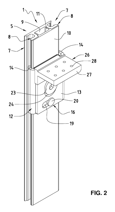
Visible in Figures 2 and 3 is part of a longitudinal section 1. This
longitudinal section 1, which can be made of a suitable metal, in particular
aluminium, has a flat base area 5 and a surface 6, opposite the base area 5,
as
well as two lateral surfaces 7. Worked into each of the two lateral surfaces 7
is
5 a first wedge surface 8. Worked into the surface 6 of the longitudinal
section 1 is
a longitudinally running groove-shaped recess 9. In a known way (not shown),
for example, cable can be run in this groove-shaped recess 9 running along the
longitudinal section 1. Also able to serve as cable ducts are the grooves
arising
in the lateral surfaces 7 through the making of the first wedge surfaces 8. In
the
10 bottom of this recess 9 continuous bores can be made, in a known way;
the
longitudinal section 1 can be fixed by means of screws to a wall or the like
in
vertical alignment.
The recess 9 of the longitudinal section 1 can be covered with a
cover section 10. This cover section 10 covers over the entire surface 6 of
the
15 longitudinal section 1. Moreover this cover section 10 is provided with
retaining
webs 9, via which this cover section 10 can be in engaged in the recess 9.
The holding means 4 are formed by a first plate-shaped basic body
12 and a second plate-shaped basic body 13. Clamping jaws 14 are fixed on
each of these plate-shaped basic bodies 12 and 13 on their sides remote from
20 one another. The first basic body 12 and the second basic body 13 are
preferably made of a metal; the clamping jaws 14 can thereby be obtained in an
easy way by means of bends 15 of the lateral regions remote from one another.
The first plate-shaped basic body 12 and the second plate-shaped basic body
13 are disposed lying on top of one another and in a way displaceable toward
25 one another. This displaceability is guided via guide means 16. These guide
means 16 in the embodiment example shown here consist of a pin 17, which is
fixed in the first plate-shaped basic body 12 and projects by a protruding
region
18 through a slot-shaped recess 19, which is provided in the second plate-
shaped basic body 13, and is provided with a head 20. Via these guide means
30 16, the first plate-shaped basic body 12 and the second plate-shaped
basic
body 13 can be displaced transversely to one another.
, =
CA 03061277 2019-10-23
7
The displacement of the first basic body 12 and of the second basic
body 13 takes place via an eccentric 21, whose rotational axis or shaft 22
(Figure 5) is borne in a rotatable way in the first plate-shaped basic body 2,
while the eccentric body 23 projects into a recess 24 of the second plate-
shaped basic body 13. Provided in the eccentric body 23 is a tool holding
device 25, which, in the embodiment example shown here, is designed as a
hexagonal opening. A suitable tool can be inserted into this tool holding
device
25; the eccentric 21 can thereby be rotated in a simple way, whereby the two
plate-shaped basic bodies 12 and 13 can be moved toward each other.
Fixed on the first plate-shaped basic body 12 is an adapter 26, on
which (as will still be described later) bearing structures for bearing shelf
boards, cabinet elements or other shelf elements can be attached. In the
embodiment example shown here, this adapter 26 consists of a supporting plate
27, which is provided with screw holes 28.
Insertable on the surface of the first plate-shaped basic body 12
turned toward the longitudinal section 1 is a protective plate 29, which is
made,
for example, of a plastic, whereby the surface of the longitudinal section 1
or
respectively the surface of the cover section 10 is protected against
scratches
from the first plate-shaped basic body 12.
Seen in Figures 4 and 5 is the holding means 4, which is placed and
tensioned on the longitudinal section 1. To place the holding means 4 on the
longitudinal section 1, the eccentric 21 is rotated in such a way that the
first
basic body 12 and the second basic body 13 are located in the moved-apart
position. The holding means 4 can then be placed on the longitudinal section 1
from the front and brought into the correct position. Afterwards the eccentric
21
is rotated in such a way that the first basic body 12 and the second basic
body
13 move toward each other. The clamping jaws 14 of the first basic body 12 and
of the second basic body 13 end up with their second wedge surfaces 30 on the
first wedge surfaces 8 of the longitudinal section 1. Through the inclination
of
these wedge surfaces 8 and 30, which have a wedge angle of about 20 degrees
to 30 degrees, an optimal clamping takes place; the holding means 4 is
moreover pressed against the surface of the longitudinal section 1. Through
this
, 9
CA 03061277 2019-10-23
8
tensioning of the two clamping jaws 14, the holding means 4 in are held in an
optimal way on the longitudinal section 1. In this state the corresponding
shelf
boards, cabinet elements or other shelf elements can be put on the adapter 26
of the holding means 4.
Seen from Figures 6a and 6b is how a shelf board 31 can be placed
on the holding means 4 or respectively its adapter 26. This shelf board 31 is
provided with a reinforcement plate 32 attached to it. By means of this
reinforcement plate 32, the shelf board 31 is screwed on the adapter 26 of the
holding means. A first cover element 33 can be put on the holding means 4. A
second cover element 34 can be put on the reinforcement plate 32 and the
adapter 26. These two cover elements 33 and 34 can be made of plastic, for
example.
Figure 7 likewise shows a shelf board 31, which is made of sheet
metal, for example. Inserted into the inner hollow space of this shelf board
31
can be a tubular element 35, which can be slipped onto the adapter of the
holding means 4 and fixed by means of screws.
In Figures 8a and 8b a longitudinal section 1 can be seen again, in
which a cabinet element 36 is inserted via the holding means 4. The adapter 26
of this holding means 4 is designed in such a way that the cabinet element 36
can be hooked or suspended via known hooking means 37 in the adapter 26
and can thereby be held in the holding means 4. Provided on the cabinet
element 36 are alignment means 38 below the hooking means 37 and thus
below the holding means 4. Via these alignment means 38 the cabinet element
36 can be aligned with respect to the longitudinal section 1, so that lateral
inclinations of the cabinet element 36 can be compensated, as will still be
described in the following.
As can be seen from Figure 9, these alignment means 38 consist of
a base plate 39, which is provided with guide means 40. These guide means 40
are formed by two bends 41, which are made in the base plate 39, and by
means of which guide rails 42 are formed. Pushed into these guide rails 42 are
two superimposed clamping plates 43 and 44, which are thereby held in a way
CA 03061277 2019-10-23
9
slidable toward one another and with respect to the base plate 39. The
clamping plate 43 lying below is provided with a clamping jaw 45, which is
disposed on the left side in the clamping plate 43 shown here. The clamping
plate 44 lying above is likewise provided with a clamping jaw 46, which, in
this
figure, is put on the right side of the clamping plate 44. These two clamping
jaws 45 and 46 project beyond the surface 47 of the base plate 39 in the
assembled state of these alignment means 38, which is why recesses 48 are
made in each of the respective plates.
The mutual displacement of the two clamping plates 43 and 44 takes
place via an eccentric 49, which is held in a rotatable way in a bore 50 in
the
clamping plate 43, while the eccentric body 51 comes to lie in a recess 52 of
the
clamping plate 44. Through rotation of this eccentric 49, the clamping plates
43
and 44 can be displaced toward one another. The clamping jaws 45 and 46 can
thus be moved toward one another and away from one another.
The two clamping plates 43 and 44 each have a slot-shaped recess
53, through which a screw 54 is led, which is screwable into a bore 55,
provided
with a threading, in the base plate 39. By tightening this screw 54, the two
clamping plates 43 and 44 are fixed in the base plate 39.
As can be seen from Figure 10, the alignment means 38 are
attached on the rear side of the cabinet element 36. To install this cabinet
element 36 on the longitudinal section 1, the cabinet element 36 with the
hooking means 37 are inserted on the adapter 26 of the holding means 4, which
are fixed on the longitudinal section 1. For this purpose, the clamping jaws
45
and 46 are located in the position moved apart from each other. In hooked-in
state of the cabinet element 36, the two clamping plates 45 and 46 are thus
located on both sides of the lateral surfaces 7 of the longitudinal section 1.
Through rotation of the eccentric 49, the two clamping jaws 45 and 46 can be
pushed against the lateral surfaces 7 of the longitudinal section 1 and
brought
into the clamping position. The screw 54 is in the released position. The
cabinet
element 36 can thus be adjusted in inclination with respect to the
longitudinal
section 1, while the clamping jaws 45 and 46 are located in the clamping
position with the longitudinal section 1. When the desired, in particular
CA 03061277 2019-10-23
horizontal, position of the cabinet element 36 is reached, the screw 54 can be
tightened; the two clamping plates 43 and 44 and thus the clamping jaws 45
and 46 are fixed with respect to the base plate 39 and thus with respect to
the
cabinet element 36, and the cabinet element 36 is located in the fixed,
aligned
5 position.
To facilitate access for manipulation of the eccentric 49 and of the
screw 54, two bores 56 are made, as can be seen from Figure 8a, respectively
in the rear wall 55 of the cabinet element 36 in the region of the eccentric
51
and of the screw 54, through which bores the eccentric 51 or respectively the
10 screws are rotatable via a suitable tool in each case.
The alignment means 38 installable on the cabinet element 36 have
been described in the previously described embodiment profile in the context
of
a longitudinal section 1, which is equipped in a corresponding way for the
shown holding means 4, but these alignment means 38 can of course be used
for any other longitudinal sections having lateral surfaces suitable for
clamping
and with which other embodiment types of holding means can be employed, in
a way co-ordinated with the longitudinal section. The holding means can be
clamped, screwed, hooked or connected in any other way to the longitudinal
section.
With this solution according to the invention, a shelf is obtained which
is very simple in construction, with which the holding means are able to be
installed on the longitudinal section in the simplest way and with optimal
fixation. The holding means are designed in such a way that practically any
desired shelf boards, cabinet elements or other shelf elements can be used,
whereby the insertion of these elements can take place in a very simple
manner.