Note: Descriptions are shown in the official language in which they were submitted.
SAMPLE AND REAGENT RESERVOIR KITS AND LINERS
WITH ANTI-VACUUM FEATURE
FIELD OF THE INVENTION
[0001] The invention relates to clinical and research laboratory
products, and in
particular, laboratory reservoir kits and liners for liquid samples and
reagents.
BACKGROUND OF THE INVENTION
[0002] Automated and semi-automated liquid handling systems often
include pipetting
heads for either 96 or 384 disposable pipette tips. A 96 pipetting head has an
array of 8 by 12
tip mounting shafts with the centerline spacing between the adjacent shafts
being 9 mm. A
384 pipetting head has an array of 16 by 24 mounting shafts with the
centerline spacing
between the adjacent shafts being 4.5 mm. The spacing is set by ANSI/SLAS
Microplate
standards (formerly known as SBS format). The
American National Standards
Institute/Society for Laboratory Automation and Screening (ANSI/SLAS) has
adopted
standardized dimensions for microplates:
ANSI/SLAS 1-2004: Microplates ___________ Footprint Dimensions
ANSI/SLAS 2-2004: Microplates ___________ Height Dimensions
ANSUSLAS 3-2004: Microplates ____________ Bottom Outside Flange Dimensions
ANSI/SLAS 4-2004: Microplates ___________ Well Positions
ANSI/SLAS 6-2012: Microplates ¨ Well Bottom Elevation
[0003] These standards have been developed to facilitate the use of
automated liquid
handling equipment with plastic consumable products from different
manufacturers.
Automated or semi-automated liquid handling systems having a matrix of fewer
mounting
shafts such as a 24 pipetting head or more mounting shafts such as a 1536
pipetting head are
also used in the field, although the most common are the 96 and 384 heads.
These automated
or semi-automated liquid handling systems are typically designed with
platforms located
underneath the pipetting head, which contain one or more nesting locations for
microplates,
racks of microtubes or reservoirs for holding samples or reagents. In the art,
microplates are
sometimes referred to as well plates, and microtubes are sometimes referred to
a sample tubes.
The nests are sized in accordance with the outside dimensions for microplates
for the SBS
- 1 -
Date Recue/Date Received 2023-09-22
standard (now ANSI/SLAS) in order to align each of the 96 or 384 pipette tips
with the center
points of the respective wells in the microplate on the platform.
[0004] As mentioned, laboratory reservoirs for holding samples or
reagents can also
be placed on the platform in the nest. Reservoirs typically have a common
basin instead of
individual wells and are known to have either a flat bottom or a patterned
bottom in order to
reduce liquid hang-up. It is also known to use a disposable reservoir liner to
avoid the need to
clean and/or sterilize reservoirs before starting a new procedure. Many
reservoirs and liners
are made of polystyrene which is naturally hydrophobic. The hydrophobic
surface causes
liquid to bead up during final aspiration which is generally thought to
facilitate liquid pick up
and reduce the residual volume.
[0005] One problem that has been found to occur with the use of
disposable reservoir
liners on automated or semi-automated 96 or 384 head systems is that one or
more of the
mounted pipette tips may engage the surface of the liner bottom when the
pipette head is
lowered. A pipette tip engaged with the surface of the liner bottom can
unfortunately create a
vacuum within the tip when the head aspirates and can draw the liner tight
against the orifice
at the bottom of the tip. The vacuum within the tip increases as aspiration
continues and the
orifice is eventually closed off. This situation can lead to inaccurate
pipetting, but can also
lead to contamination of the pipetting head which is a serious issue. When a
pipette tip that
has vacuum engaged the liner bottom releases, the reagent or sample, now
driven by a
significant pressure difference, often sprays upward beyond the pipette tip
and the mounting
shaft into the respective piston cylinder. If this occurs, it may be necessary
to disassemble,
clean and sterilize the entire pipette head.
[0006] It is often desirable to reduce residual volume or liquid hang-up
in the liner
when attempting to fully aspirate all the liquid from the liner. To this end,
pipette tips are
typically lowered as close to the bottom wall of the liner without contacting
the bottom wall
as reasonably possible in order to reduce the residual volume of liquid that
cannot be aspirated.
In multi-channel pipetting systems, even automated multi-channel systems where
the height of
the pipetting head can be controlled precisely, one or more pipette tip
orifices can become
misaligned with the other tip orifices because, for example, a pipette tip is
mismounted or
deformed. Tip misalignment can lead to the tip engaging the bottom wall and
forming a
- 2 -
Date Recue/Date Received 2023-09-22
vacuum. Even if all of the pipette tips are aligned properly, it is possible
that the portions of
the bottom wall in the liner corresponding to the locations of the pipette
tips are not precisely
aligned on a plane level with the pipette tip orifices. This sort of
unevenness can occur, e.g.,
when a liner is not fully seated in a reservoir base or is slightly deformed,
and can also lead to
one or more pipette tips engaging the bottom wall when trying to aspirate the
final volume
from the container.
SUMMARY OF THE INVENTION
[0007] The invention relates primarily to the placement of anti-vacuum
channels on
the bottom wall of a disposable reservoir liner used in laboratory reservoir
kits.
[0008] In one aspect, the invention is directed to features of the
disposable liner. In
another aspect, the invention is directed to features of the kits including a
disposable liner that
is held within a reusable reservoir base. The disposable liner and the
reusable reservoir base
are designed so that the liner fits into the base and provides stable support
for the liner with the
bottom wall of the liner sitting on the reservoir base. The disposable liner
is especially
configured to prevent pipette tips from vacuum engaging the bottom wall of the
liner basin.
To do this, an upper surface of the bottom wall of the liner basin includes
multiple anti-vacuum
channels that face upwardly towards the volume in which the liquid sample or
liquid reagent
is held. The bottom wall has a generally rectangular shape configured to
enable a matrix of
pipette tips to aspirate liquid from the volume in the liner basin. The
purpose of the anti-
vacuum channels is to provide a fluid accessible void underneath the orifice
of the pipette tip
even when the tip is pressed against the upper surface of the bottom wall of
the liner. It has
been found that using the anti-vacuum channels and keeping the bottom wall of
the liner
straight or flat also generally reduces the residual volume of liquid
remaining in the liner when
it is attempted to fully aspirate liquid from the liner with a 96 or 384 tip
pipetting head,
compared to liners without the anti-vacuum channels.
[0009] In one embodiment, the liners are made of molded polystyrene
which is
generally considered to be hydrophobic as discussed above. However, it has
been found that
corona treating the polystyrene liners with the anti-vacuum channels, in order
to render the
bottom wall more hydrophilic, further reduces the residual volume remaining in
the liner when
- 3 -
Date Recue/Date Received 2023-09-22
it is attempted to fully aspirate liquid with a 96 or 384 tip pipetting head.
It is preferred that the
corona treatment be sufficient to render the measured surface tension of the
bottom wall of the
liner greater than or equal to about 72 dynes/cm, which is the surface tension
for natural water.
In another embodiment, the liner is made from molded polypropylene. This
embodiment is
particularly useful for applications where chemical resistance is more
important. Polystyrene
is stiffer than polypropylene, however, which is often beneficial in the
laboratory.
[0010] Desirably, the reusable reservoir base has outside flange
dimensions
compatible with nests configured to hold SBS-formatted well plates and
reservoirs (i.e.
ANSI/SLAS 3-2004: Microplates ¨ Bottom Outside Flange Dimensions). If the
reservoir is
made to be used with a 96 pipetting head, the disposable liner contains a
matrix of 96 groupings
of anti-vacuum channels with a center point for each grouping spaced 9 mm from
the center
point of adjacent groupings, consistent with SBS (ANSI/SLAS) formats. If the
disposable
liner is designed to be used with a 384 pipetting head, the liner desirably
contains a matrix of
384 groupings of anti-vacuum channels with the center point for each grouping
spaced 4.5 mm
from the center point of adjacent groupings, again consistent with SBS
(ANSI/SLAS) formats.
The disposable liner can also be made with more or less groupings depending on
the intended
use of the liner; however, in each case the groupings should be centered at
the center point at
which it is expected that the pipette tips on the pipetting head will be
located. In some
embodiments, the liner contains a matrix of 96 groupings of anti-vacuum
channels with
adjacent center points spaced 9 mm apart, as well as a matrix of 384 groupings
of anti-vacuum
channels having center points spaced apart 4.5 mm. In this manner, the liner
is configured to
be used both with a 96 pipetting head or a 384 pipetting head.
[0011] The groupings of the anti-vacuum channels can take on various
configurations
in accordance with the invention. The goal is to provide a channel
configuration that will
provide a fluid accessible void underneath the orifice of the respective
pipette tip even if the
pipette tip is somewhat off center, which can occur in an automated pipetting
system, for
example, when a pipette tip is not mounted straight or the tip is slightly
deformed. One desired
grouping configuration includes a first pair of perpendicular and intersecting
channels with the
intersection of the channels defining a center point for the grouping, and a
second pair of
perpendicular channels rotated 45 from the first pair where the second pair
of channels are
- 4 -
Date Recue/Date Received 2023-09-22
aligned to intersect at the center point but are interrupted in the vicinity
of the center point. It
is desirable that the channels have a constant width (except for necessary
draft angles required
for reliable molding) and a constant depth, and that the width of the channels
is selected so
that the distance across the intersection is less than the outside orifice
diameter of the smallest
sized pipette tips that will likely be used with that liner. For example, if a
12.5 ill pipette tip
has an outside orifice diameter of 0.61 mm, then the width of the channels
should be less than
or equal to about 0.50 mm to ensure that the distal end of the pipette tip
cannot fit into the
channels at the intersection. For a 384 application, the desired channel width
using the above
described grouping configuration is 0.50 mm +/- 0.10 mm. For a 96 head
application, the
desired width is 0.50 mm +/- 0.10 mm as well. The grouping may also have other
channels
located away from the center point towards the perimeter of the grouping in
order to provide a
larger region covered by anti-vacuum voids in the event that the pipette tip
orifice is off center
because of how the tip is mounted or constructed, or in the event it is used
with a hand-held
pipette. Providing a bigger area of coverage by the channels over the bottom
wall, also creates
a higher likelihood that peripheral liquid will be drawn into the channels of
the grouping when
liquid is being drawn by a pipette tip, which in turn tends to reduce the dead
volume or residual
volume, other factors being equal. In one embodiment, a circular channel
intersects each of
the first and second pair of channels.
[0012] In some embodiments, additional channels are located between
adjacent
groupings to fluid dynamically connect adjacent groupings of anti-vacuum
channels. In other
embodiments, such as those shown in the Figures, no channels extend between
adjacent
groupings of anti-vacuum channels.
[0013] In the disclosed embodiments, the bottom wall of the disposable
liner is
otherwise flat, and the groupings of anti-vacuum channels are located at the
center point for
either a 96 pipetting head or a 384 pipetting head configuration or both. The
disposable liner
desirably is made of a transparent plastic material, such as clear molded
polystyrene or
polypropylene as mentioned above, and has a shape that closely follows the
contour of the
basin of the reusable base, in part to facilitate viewing of liquid volume
graduation marks on
the side walls of the base. Also desirably, the side walls of the reusable
reservoir base have
distinct liquid volume graduation marks on the surface of the side wall
forming a portion of
- 5 -
Date Recue/Date Received 2023-09-22
the basin. These liquid volume graduation marks are calibrated to measure a
volume of liquid
sample contained in the transparent disposable liner and are observable when
the disposable
liner is set in place within the reusable base. Further, one or more sides of
the reusable base
may contain one or more viewing windows so that a user can easily view the
amount of liquid
contained in the disposable liner. The viewing window can be a narrow window
or it can be
relatively wide as long as the base still has enough support for the
disposable liner.
[0014] In some embodiments, the laboratory reservoir kit includes a lid
to cover liquid
contained in a liner placed within the reusable base. It is preferred that the
lid be transparent to
facilitate viewing of contained liquid or reagent when the lid is latched in
place. A gasket is
provided optionally on the lid, and a locking mechanism on the reservoir base
is used to lock
the lid in place and secure the liner between the gasket on the lid and the
base to seal the
contained liquid. The lid is also preferably configured to facilitate stacking
of kits with the lid
attached. The locking mechanism can also be used to hold the liner in place
during use when
the lid is removed.
[0015] Advantageously, the use of anti-vacuum channels on the bottom
wall of the
disposable liner provides a fluid accessible void even if a pipette tip
engages the bottom wall
of the liner. This means that the pipette tip will not cause a vacuum within
the tip while the
pipette is aspirating. It also means that, as a practical matter, tips can be
placed closer to the
bottom wall of the liner and/or engage the bottom wall of the liner when doing
so without the
anti-vacuum feature would more likely cause vacuum engagement. In turn, with
the ability to
move the pipette tip orifice very close to or into engagement with the bottom
wall of the liner,
the pipetting system is able to withdraw liquid from the container with
significantly less
residual volume. In addition, without being limited to a theory of operation,
it is believed that
the hydrophilic nature of the corona treated surface causes liquid on the
surface to self level,
while the channels provide surface tension features that accumulate liquid on
the surface. The
result is that the liquid draws naturally from the surface between the
groupings of channels and
forms segregated pools in and above the groupings of channels, as the liquid
level is drawn
down. This phenomenon effectively lowers the minimum working volume for
reliable
pipetting. This is particularly important for expensive, scarce or small
samples or reagents.
- 6 -
Date Recue/Date Received 2023-09-22
[0016] Other features and advantages of the invention may be apparent to
those skilled
in the art upon reviewing the drawings and the following description thereof.
BRIEF DESCRIPTION OF THE DRAWINGS
[0017] Fig. 1 is a laboratory reservoir kit constructed in accordance
with a first
exemplary embodiment of the invention, which is configured for a 384 pipetting
head.
[0018] Fig. 2 is an assembled view of the kit shown in Fig. 1.
[0019] Fig. 3 is a top plan view of the laboratory reservoir kit shown
in Fig. 2. The
placement of the channel groupings in Figs. 1-3 is illustrative of the
placement of the channel
groupings in a reservoir configured for a 384 pipetting head, but reference to
Fig. 4 should be
made for the configuration of the channels in the groupings.
[0020] Fig. 4 is a detailed view showing the configuration of the
channels in the
channel groupings of a reservoir configured for a 384 pipetting head.
[0021] Fig. 5 is a schematic sectional view showing a pipette tip
engaging the bottom
wall of the reservoir with a channel below the tip orifice. .
[0022] Fig. 6 is a detailed view of the region shown by line 6-6 in Fig.
5.
[0023] Fig. 7 is a side elevational view of the laboratory reservoir kit
shown in Figs. 1
through 6.
[0024] Fig. 8 is an end elevational view of the laboratory reservoir kit
shown in Figs.
1 through 7.
[0025] Fig. 9 is a laboratory reservoir kit constructed in accordance
with another
exemplary embodiment of the invention, which is configured to be used with
either a 96
pipetting head or a 384 pipetting head, and shows the kit assembled with a lid
secured to the
kit.
[0026] Fig. 10 is perspective view of the laboratory reservoir kit shown
in Fig. 9 with
the lid exploded away from the remaining components of the kit.
[0027] Fig. 11 is a detailed sectional view taken along line 11-11 in
Fig. 9, showing
the interaction of the locking mechanism to attach the lid to the kit.
[0028] Fig. 12 is a bottom plan view of the lid shown in Figs. 9 and 10
illustrating a
peripheral sealing gasket.
- 7 -
Date Recue/Date Received 2023-09-22
[0029] Fig. 13 is a perspective view of the kit with the lid removed
showing use with
pipette tips.
[0030] Fig. 14 is a top plan view of the laboratory reservoir kit shown
in Figs 9
through 21 with the lid removed in order to show the liner and the anti-vacuum
channels on
the bottom wall of the liner.
[0031] Fig. 15 is a detailed view of the region depicted by line 15-15
in Fig. 14.
DETAILED DESCRIPTION
[0032] Figs. 1 through 8 illustrate a laboratory reservoir kit 10 for
liquid samples and
reagents constructed in accordance with the first embodiment of the invention.
The kit 10
includes a reservoir base 12 and a disposable liner 14. Figs. 1 through 8 also
show an
exemplary pipette tip 16. The kit 10 is designed to hold liquid sample or
liquid reagent in the
disposable liner 14 when the disposable liner 14 is placed within the reusable
reservoir base 12
as shown for example in Fig. 2. The kit 10 is designed to hold up to 100 ml of
liquid sample
or reagent although the capacity of the disposable liner 14 is sufficient to
handle substantial
overfilling. As mentioned previously, the use of a low retention pipette tip
16 may be
particularly effective when using the reservoir kit 10 in order to minimize
waste of scarce or
expensive liquid samples or reagents.
[0033] The reservoir base 12 contains a basin 18 into which the
disposable liner 14 is
placed. The contour of the disposable liner 14 closely follows the shape and
contour of the
basin 18 of the reusable base 12. Outer side walls 22 and end walls 20 on the
reusable base 12
provide support for the reservoir base 12 and its basin 18 on flat surfaces
such as a laboratory
bench top. While the reservoir base 12 can be made of a variety of materials,
it is preferred
that the base 12 be made of relatively rigid injection molded plastic having
an opaque color
such as white ABS. It is preferred that the surface of the basin 18 have a
satin finish. On the
other hand, as mentioned above, it is preferred that the disposable liner 14
be made of clear
transparent plastic and have a polished surface (at least the sidewalls and
peripheral flange),
such as clear injection molded polystyrene or polypropylene having a thickness
of
approximately 0.51 mm. The polished or shiny surface of the clear liner, in
contrast to the
satin finish on the opaque color basin 18 in the base 12, renders the
transparent liner 14 more
- 8 -
Date Recue/Date Received 2023-09-22
conspicuous to laboratory workers tying to determine whether or not it is
present within the
reservoir base 12. Injection molding is the preferred method to manufacture
the disposable
liner 14 because it is desirable for the liner thickness to be constant
throughout. It should be
recognized, however, that other manufacturing methods and thickness
specifications may be
possible for both the disposable liner 14 and the reusable base 12.
[0034] When the disposable liner 14 is made of molded polystyrene or
polypropylene,
e.g., it is desirable to corona treat or otherwise treat the liner after
molding in order to render s
the plastic surface more hydrophilic, which means that small amounts of liquid
remaining in
the liner tend to flatten out on the surface of the bottom wall rather than
bead up. However,
the capillary action of the channels tends to draw the liquid into pools above
the channel
groupings as the liquid is drawn down. It is generally believed in the art
that providing a
hydrophobic surface, so that small amounts of liquid tend to bead up, would
normally be the
best way to reduce the amount of residual volume after pipetting from a
reservoir or a reservoir
liner. With the use of anti-vacuum channels as described herein, the inventors
have found it
advantageous to corona treat the surface rendering it more wettable and
hydrophilic, thereby
providing a surface on which the liquid tends to spread evenly, with the
capillary action of the
channels being responsible for creating pools or beads of liquid suitable for
effective pipetting
at the final draw down. With the anti-vacuum channels and the fluid accessible
voids
underneath the pipette tip orifices, even if tips are engaging the bottom
surface of the liner, the
hydrophilic surface facilitates more even fluid distribution available for
aspiration from
multiple pipette tips and less residual volume after complete aspiration of
liquid from the
container. As mentioned, it is desirable to treat the surface so that its
surface tension is greater
than or equal to 72 dynes/cm, which is the surface tension for natural water.
[0035] The disposable liner 14 can be made of polypropylene for
applications in which
chemical resistance is desired. The polypropylene liner should likewise be
corona treated or
otherwise treated so that its surface tension is greater than or equal to the
surface tension of
water, 72 dynes/cm.
[0036] The basin 18 in the reusable base 12 is rectangular and extends
between the
bottom of the end walls 20 and the side walls 22. The rectangular basin is
compatible with the
SBS format and is sized for a 384 pipetting head or a 96 pipetting head. The
disposable liner 14
- 9 -
Date Recue/Date Received 2023-09-22
shown in Figs. 1 through 8 is designed for a 384 pipetting head, although the
rectangular
footprint of the basin 18 in the reusable base 12 should be the same whether
the disposable
liner 14 is designed for a 384 pipetting head or a 96 pipetting head. The
bottom wall 24 of the
basin 18 in the reusable base 12 is flat. Referring to Fig. 5, the disposable
liner 14 is configured
to fit in the base 12 so that the bottom wall 24, the end walls 20 and the
longitudinal side
walls 22 (see Fig. 1) of the base 12 support the disposable liner 14 with the
bottom wall 26 of
the liner 14 sitting on the bottom wall 24 of the reservoir base 12. As can be
seen in Fig. 5 as
well as the other drawings, the bottom wall 26 of the disposable liner 14 in
this embodiment is
flat.
[0037] Referring to Figs. 2 through 4, the bottom wall 26 of the
disposable liner 14
includes a matrix of 384 groupings of anti-vacuum channels 28. The anti-vacuum
channels 28
are exposed upwardly towards the volume 30 in which liquid sample or liquid
reagent is held
in the disposable liner 14. The bottom wall 26 of the liner 14 has a generally
rectangular shape
configured to enable the entire matrix of 384 pipette tips arranged in SBS
format to aspirate
liquid sample or liquid reagent from the disposable liner 14. The disposable
liner 14 includes
a peripheral flange 32 that extends outwardly from an upper end of the liner
side walls 34 and
end walls 36. The peripheral flange 32 on the disposable liner 14 may rest or
touch slightly on
the upper rim 40, see Fig. 1, of the base 12 when the disposable liner 14 is
placed within the
base; however, the bottom wall 26 of the disposable liner 14 should rest on
the bottom wall 24
of the reusable base 12. The peripheral flange 32 helps to secure the
disposable liner 14 within
the base 12, and also facilitates lifting of the disposable liner 14 by
laboratory workers. It is
advised that the user lift the disposable liner 14 from the reusable base 12
to the position shown
for example in Fig. 1 before pouring liquid from the liner 14. In order to
facilitate such pouring,
the disposable liner 14 includes pouring spouts 60 at each corner. The front
side wall 22 of
the base 12 includes a cut out region (shown as 369 on Fig. 10) which serves
as a window so
that the user can easily see the liner 14 when it sits in the base 12.
Although not necessarily
preferred, a transparent insert can be placed across the window 369.
[0038] Liquid volume graduation marks (62), see Figs. 2, 5 and 7, are
molded or
printed onto the side wall 22 of the reusable base 12. The liquid volume
graduation marks (62)
are preferably printed onto the side wall 22 using pad printing or any other
suitable process.
- 10 -
Date Recue/Date Received 2023-09-22
The liquid volume graduation marks (62) on the side wall can be seen by the
user through the
clear, transparent liner 14 when the liner 14 is placed in the base 12. Figs.
2, 5 and 7 show the
liner 14 placed in the base 12, and illustrate that the liquid volume
graduation marks (62) on
the side wall 22 of the base 12 can be viewed through the transparent
disposable liner 14. In
Figs. 2, 5 and 7 the reference number (62) for the liquid graduation marks has
been placed in
parenthesis to indicate that the marks on the opaque surface of the base 12
underlies the clear
transparent liner 14. Likewise, reference number (22) is placed in parentheses
to indicate that
the side wall of the base 12 underlies the transparent liner 14 in these
figures as well. Volume
indicators may also be printed on the side wall (22) of the base 12. While the
values for the
volume indicators are not illustrated per se in the drawing, a 100 ml kit 10
would typically
include values of 20, 40,60, 80 and 100 adjacent the associated volume liquid
graduation mark.
Since the kit 10 is intended to be used with the disposable liner 14 set in
place within the
base 12, the location of the graduation marks (62) is calibrated with respect
to the volume of
liquid contained within the disposable liner 14 when the disposable liner is
in place, not with
respect to the volume of the basin of the base 12. It is desired that the
volume indicators on the
basin side wall (22) of the base 12 be printed at or above the calibrated
liquid volume
graduation marks (62) to which they are associated, so that liquid within the
liner does not
obstruct reading of the respective volume indicator.
100391
Referring again to Fig. 1, the bottom flange 64 on the base 12 has outside
wall
dimensions compatible with SBS standards (namely ANSI/SLAS 3-2004:
Microplates ¨ Bottom Outside Flange Dimensions). Having SBS compatible outside
wall
dimensions means that the base 12 will fit into platform nests for liquid
handling systems
having a 96 or 384 pipetting head, and be in alignment so that each of the
pipette tips aligns at
least generally with one of the groupings of anti-vacuum channels 28.
Referring now to Fig. 4,
it is desired that each grouping of anti-vacuum channels 28 have a similar
configuration for a
given liner. However, it is possible that one or more of the groupings of anti-
vacuum channels
have a different configuration than the other groupings of the anti-vacuum
channels on the
liner. Referring to the groupings identified by reference number 28 in Fig. 4,
each grouping
of anti-vacuum channels has a center point 66, and since the liner 14 shown in
Figs. 1 through 8
is for a 384 pipetting head, the spacing between adjacent center points 66 is
4.5 mm in
- 11 -
Date Recue/Date Received 2023-09-22
accordance with SBS standards. By way of example, Figure 4 shows a pipette lip
16 aligned
with the centerpoint 66 of one of the groupings of anti-vacuum channels. Each
grouping 28
contains a first pair of perpendicular intersecting channels 68 with the
intersection 66 defining
the center point for the grouping 28. In Fig. 4, the first pair of
perpendicular and intersecting
channels 68 are the vertical channel 68 and the horizontal channel 68 (as
viewed in Fig. 4).
The grouping 28 also includes a second pair of perpendicular channels 70 that
are rotated 45
from the first pair 68 of channels. The channels in the second pair 70 are
aligned to intersect
at the center point 66 but are interrupted in the vicinity of the center point
66. Therefore, an
irregularly shaped pedestal 72 at the height of the upper surface of the
bottom wall 26 is formed
between the channels 68 and 70. Allowing the second pair of channels 70 to
continue through
the center point 66 would create an air space around the center point 66
having too great of a
diameter to obstruct continued downward movement of the lower distal end of
the smallest
sized pipette tip that the disposable liner 14 is designed to be used with.
For example, a 12.5
pipette tip may have a lower orifice with an outside diameter of 0.61 mm and
an inside diameter
of 0.30 mm. The width and configuration of the channels 68, 70 should be
selected so that
there are no channel areas in which the 0.61 mm orifice can fit down into. The
channel
configuration should also be designed so that at least a portion of the
orifice opening having
an inside diameter of 0.30 mm spans over an open channel even if the tip is
pressed down
against the liner 14 at or near the center point 66. In the exemplary
embodiment, for the
channel grouping 28 shown in Figs. 4 and 5 for a 384 pipetting head, the
channels 68, 70 have
a generally constant width of 0.50 mm 0.10 mm, although a draft angle for
molding must be
accounted for. It is also desirable that for the depth of the channels 68, 70
be constant, e.g.
0.30 mm 0.10 mm. In Fig. 4, the channel groupings 28 also include a circular
channel 72
spanning between the first pair 68 and second pair 70 of channels. This
circular channel 72
provides more tolerance for pipette tip misplacement.
[0040]
Figs. 5 and 6 show the kit 10 in use with an exemplary pipette tip 16 pressing
down on to the bottom wall 26 of the liner 14 with the pipette tip 16 aligned
with a grouping
of anti-vacuum channels 28. The bottom of the pipette tip 16 is pressing
against pedestals 72
between the intersecting channels at the center point 66 of the grouping 28
and the third pair
of channels 74, see Fig. 4. The inner orifice of the pipette tip 16 resides
directly over the
- 12 -
Date Recue/Date Received 2023-09-22
intersecting channels at the center point 66, even when the pipette tip 16 is
pressed down
against the bottom floor 26 of the liner 14. hi this way, no vacuum is created
when the pipette
is operated to aspirate liquid into the pipette tip 16.
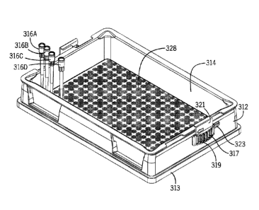
[0041] Figures 9 through 15 illustrate a liquid reagent reservoir kit
310 constructed in
accordance with another embodiment of the invention. The reservoir kit 310
includes a
disposable liner 314 that is similar in many respects to the disposable liner
14 shown in Figs. 1
through 8; however, the disposable liner 314 is designed to be used with both
a 96 pipetting
head and a 384 pipetting head. Again, as apparent in the drawings, the bottom
wall of the
liner 314 is flat except for the anti-vacuum channels. The reservoir kit 310
has a reusable
reservoir base 312 which in many respects is similar to the reusable base 12
shown in Figs. 1
through 8. The reservoir kit 310 is designed to hold up to 150 mL of liquid
but other sizes,
such as 300 mL, can be made by increasing or decreasing the height of the
sidewalls of the
liner 314 and the base 312. The kit 310 also includes a lid 315 which is
preferably transparent
to enable the user to view liquid contained in the liner 314. Locking
mechanisms 317 located
on the base 312 are used to lock the lid 315 in place over the liner 314 and
any contained liquid
or reagent. Figures 9 through 15 generally illustrate one locking mechanism on
one side of the
kit 10, but it should be understood that another locking mechanism is located
on the other side
of the kit 10. The locking mechanism 317 includes a finger grip 319 and a
latch arm 321 that
is mounted through an elongated slot 323 in the side wall of the base 312. A
sliding attachment
arm 325 holds the locking mechanism 317 in the elongated slot 323 as shown in
Fig. 11. The
locking mechanism 317 can be slid from an unlocked position which is located
to the right side
of the elongated slot 323 in Fig. 10 to a locked position which is located to
the left most position
in elongated slot 323 as depicted by the arrow shown in Fig. 10 on the latch
arm 321. In Fig. 9,
the locking mechanism 317 is shown midway between the unlocked position and
the locked
position.
[0042] Fig. 12 shows the underside of the lid 315. A gasket 337 or seal
is located
around the periphery of the lid 315. The gasket 337 is an optional feature.
Referring to
Fig. 11, the gasket 337 presses against the peripheral flange 332 of the liner
314 when the
lid 315 is locked in place, thereby providing a circumferential seal around
the top of the
liner 314. The gasket 337 shown in the drawings has a flat cross section;
however, other types
- 13 -
Date Recue/Date Received 2023-09-22
of gaskets may be suitable. For example, using a gasket with a stepped cross
section can
provide more robust sealing. The stepped cross section not only enables the
gasket to press
against the peripheral flange 332 of the liner 314 when the lid 315 is locked
in place but also
press against liner at the intersection between the sidewall of the liner and
the peripheral
flange 332. When a gasket is used, the lid is preferably molded from
polypropylene. The use
of a gasket, however, is not desirable if the reservoir is intended to be
removed robolically.
For robotic applications, the lid is desirably made of polystyrene, which is
stiffer than
polypropylene, and without a gasket. Still referring to Fig. 11, the latch arm
321 extends
upward and then inward to engage the upper rim 333 of the lid 315. The rim 333
includes an
upwardly extending fastening lip 335 which facilitates reliable attachment of
the lid 315 to the
base 312 when the locking mechanism 317 is engaged in the locked position.
Referring for
example to Fig. 10, the peripheral rim 333 of the lid 315 has cutouts 338
corresponding to the
unlocked position of the locking mechanism 317. The base 312 has a second
sliding locking
mechanism on the other end wall. Including four cutouts 338 as shown in the
figures enables
the lid to be placed in either direction. The lid 315 also includes guide
ridges 339 on the top
surface of the lid 315 to facilitate stable stacking of the kits 310 when, for
example, liquid is
stored in the liner 314 and the lid 315 is locked into place. The Ode ridges
are dimensioned
to fit within the lower outer wall flange 313 of the base 312. As discussed
with respect to the
earlier embodiment, the lower outer wall flange 313 of the base 312 has an
outside dimension
to fit within an SBS formatted nest in order to facilitate use with automated
or semi-automated
pipetting equipment.
100431 The peripheral flange 332 of the liner 314 also includes cut outs
having a shape
and location corresponding to the cut outs 338 on the lid 315. The cut outs in
the peripheral
flange 332 of the liner 314 allow the flange of the liner to be placed flat on
the top of the wall
of the reusable base 312. The locking mechanisms 317 can be slid into the
locking position,
when the lid 315 is not in place, in order to hold the liner 314 flat in the
reusable base 312.
Keeping the bottom of the liner 314 flat reduces the retained volume of liquid
after attempting
to fully aspirate all the liquid from the liner 314 with a 96 or 384 pipetting
head.
100441 Referring now to Figs. 13 through 15, the liner 314 contains
groupings 328 of
anti-vacuum channels designed to accommodate both a 96 pipetting head and a
384 pipetting
- 14 -
Date Recue/Date Received 2023-09-22
head. Figs. 13 and 15 show exemplary pipette tips 316A, 316B, 316C, 3161/ The
pipette
tips 316A and 316B represent tips on a 384 head and are spaced apart at 4.5 mm
centerline
spacing. The pipette tips 316C and 316D represent tips on a 96 head and are
spaced apart at
9 mm centerline spacing.
[0045] In this embodiment, some of the anti-vacuum channels are shared
between
groupings 329 for the 96 pipetting head and the groupings 429 for the 384
pipetting head.
Fig. 15 shows the groupings 329, 429 in detail. The groupings labeled 329 for
the 96 head
includes intersecting linear channels 370. The anti-vacuum channels 370 extend
beyond the
area in which they are expected to be used for pipette tips on a 96 head and
are part of the
groupings 429 of anti-vacuum channels used for a 384 head. The 384 head
groupings 429
include horizontal and vertical channels 470 and diagonal channels 472 in
addition to a circular
channel. The center points of the 384 head groupings are designated by
referenced number 466
and the distance between adjacent center points for 384 head groupings is 4.5
mm as depicted
in Fig. 3. The center points for 96 head groupings is designated by reference
number 366 and
the distance between center points 366 for adjacent 96 head groupings 329 is 9
mm as also
depicted in Fig. 15. In this embodiment, all the channels have a width of 0.50
mm +/- 0.10
mm (constant width accounting for draft angle is desired) and a constant depth
of
0.3 mm +/- 0.1 mm.
[0046] Although not illustrated in the embodiments shown in Figures,
additional
channels can be optionally located between adjacent groupings to fluid
dynamically connect
adjacent groupings of anti-vacuum channels. Some or all of the groupings can
be fluid
dynamically connected directly or indirectly in this manner. The capillary
action tends to even
fluid distribution among the connected channels, which can in turn reduce the
minimum
working volume for reliable pipetting with multiple pipette tips.
[0047] As described above, the liner 314 is desirably made of a molded
transparent
plastic, in part so that graduation marks (not shown) on the inside surface of
the sidewall of
the base 312 can be read by the user, as described with respect to the
embodiment disclosed in
Figs. 1 through 8. In one desired embodiment, the liner 314 is made from
molded polystyrene
or polypropylene and is corona treated or otherwise treated so that the bottom
wall of the plastic
liner has increased wettability compared to the bottom wall of the polystyrene
liner before
- 15 -
Date Recue/Date Received 2023-09-22
corona treatment, and desirably so that the surface tension of the bottom wall
of the liner is
greater than or equal to about 72 dynes/cm which is the surface tension of
natural water. It has
been found that this treatment along with the use in the above illustrated
reservoir kit 310, as
shown in Figs. 9 through 15, is especially effective at minimizing dead volume
or residual
volume. Dead volume can vary on a number of factors including the type of
liquid being
pipetted. The measured dead volume of water using 384 12.5 ml tips for the
embodiment
shown in Figs. 9 through 15 with corona treated polystyrene liners 314 can be
less than 3 ml.
This is measured in accordance with the common practice stopping an aspiration
cycle in a
multi-channel pipette as soon as one of the tips aspirates air. Then,
reversing the direction of
the pipette until liquid is dispensed from all of the tips, including the tip
aspirating air, so that
an equal volume of liquid is in each tip. The tips are also touched off to
release any additional
liquid. Of course, minimizing dead volume or the required minimum working
volume may be
a secondary goal in certain applications, yet the invention is still useful to
eliminate the
potential of the pipette tip vacuum engaging with the bottom wall of the
liner.
[0048] The
present invention is not limited to the exemplary embodiments described
above so long as it is covered by the subject matter of the claims that
follow.
- 16 -
Date Recue/Date Received 2023-09-22