Note: Descriptions are shown in the official language in which they were submitted.
CA 03061487 2019-10-24
WO 2018/226970 PCT/US2018/036478
SAMPLE AND REAGENT CONTAINERS WITH ANTI-VACUUM FEATURE
FIELD OF THE INVENTION
[0001] The invention relates to clinical and research laboratory
products, and in
particular, pipetting containers such as reagent reservoirs, liners,
microtubes, PCR tubes, PCR
plates and microplates.
BACKGROUND OF THE INVENTION
[0002] Automated and semi-automated liquid handling systems often include
pipetting
heads for either 96 or 384 disposable pipette tips. A 96 pipetting head has an
array of 8 by 12 tip
mounting shafts with the centerline spacing between the adjacent shafts being
9 mm. A 384
pipetting head has an array of 16 by 24 mounting shafts with the centerline
spacing between the
adjacent shafts being 4.5 mm. The spacing is set by ANSI/SLAS Microplate
standards (formerly
known as SBS format). The American National Standards Institute/Society for
Laboratory
Automation and Screening (ANSYSLAS) has adopted standardized dimensions for
microplates:
AN S S 1-2004: Mieroplates Footprint Dimensions
ANSUSLAS 2-2004: Microplates ----------- Height Dimensions
A NS liS LAS 3-2004: Micropiates _______ Bottom Outside Fl a n ge Dimensions
AN S S 4-2004: M ic rop 1 ales .. Well Positions
ANSYSLAS 6-2012: Microplates = --------- Well Bottom Elevation
[0003] These standards have been developed to facilitate the use of
automated liquid
handling equipment with plastic consumable products from different
manufacturers. Automated
or semi-automated liquid handling systems having a matrix of fewer mounting
shafts such as a
24 pipetting head or more mounting shafts such as a 1536 pipetting head are
also used in the
field, although the most common are the 96 and 384 heads. These automated or
semi-automated
liquid handling systems are typically designed with platforms located
underneath the pipetting
head, which contain one or more nesting locations for microplates, racks of
microtubes or
reservoirs for holding samples or reagents. In the art, microplates are
sometimes referred to as
well plates, and microtubes are sometimes referred to a sample tubes. The
nests are sized in
accordance with the outside dimensions for microplates for the SBS standard
(now ANSI/SLAS)
-1-
CA 03061487 2019-10-24
WO 2018/226970 PCT/US2018/036478
in order to align each of the 96 or 384 pipette tips with the center points of
the respective wells
in the microplate on the platform.
[0004] As mentioned, reservoirs for holding samples or reagents can also
be configured
to be placed on the platform in the nest. Reservoirs typically have a common
basin instead of
individual wells and are known to have either a flat bottom or a patterned
bottom in order to
reduce residual liquid waste. It is also known to use a disposable reservoir
liner to avoid the
need to clean and/or sterilize reservoirs before starting a new procedure. In
addition to
automated and semi-automated systems, handheld pipettes are used to draw
reagents or samples
from reservoirs, microplates or microtubes. One reservoir kit that uses a
liner is disclosed in US
Pat. No. 7,811,522 entitled "Sample Reservoir Kits with Disposable Liners" and
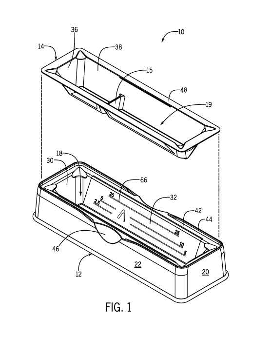
issuing on
October 12, 2010 to Mathus et al. , incorporated herein by reference, is
particularly well suited
for use with handheld pipettes. Many reservoirs and liners are made of
polystyrene which is
naturally hydrophobic. The hydrophobic surface causes liquid to bead up and
pool during final
aspiration which is generally thought to facilitate liquid pick up and reduce
the residual volume.
[0005] One problem that has been found to occur with the use of
reservoirs or
disposable reservoir liners is that one or more of the mounted pipette tips
may engage the surface
of the liner bottom when the pipette head is lowered. A pipette tip engaged
with the surface of
the bottom wall can unfortunately create a vacuum within the tip when the head
aspirates. The
vacuum within the tip increases as aspiration continues and the orifice is
eventually closed off.
This situation can lead to inaccurate pipetting, but can also lead to
contamination of the pipetting
head which is a serious issue. When a pipette tip that has vacuum engaged the
bottom wall
releases, the reagent or sample, now driven by a significant pressure
difference, often sprays
upward beyond the pipette tip and the mounting shaft into the respective
piston cylinder. If this
occurs, it may be necessary to disassemble, clean and sterilize the entire
pipette head.
[0006] The problem of pipette tips possibly engaging the bottom of a
container and
forming a vacuum during aspiration can also occur in reservoirs without
liners, or in other
containers typically used for pipetting such as microtubes or microplates. In
all of these
applications, it is often desirable to reduce residual volume or liquid hang-
up in the container
when attempting to fully aspirate all the liquid from the container. To this
end, pipette tips are
typically lowered as close to the bottom wall of the container without
contacting the bottom wall
-2-
CA 03061487 2019-10-24
WO 2018/226970 PCT/US2018/036478
as reasonably possible in order to reduce the residual volume of liquid that
cannot be aspirated.
In multi-channel pipetting systems, even automated multi-channel systems where
the height of
the pipetting head can be controlled precisely, one or more pipette tip
orifices can become
misaligned with the other tip orifices because, for example, a pipette tip is
mismounted or
deformed. Tip misalignment can lead to the tip engaging the bottom wall and
forming a
vacuum. Even if all of the pipette tips are aligned properly, it is possible
that the portions of
bottom wall in the container or container(s) corresponding to the locations of
the pipette tips are
not precisely aligned on a plane level with the pipette tip orifices. This
sort of unevenness can
occur, e.g., when one or more microtubes are not completely seated in the tube
rack, or when a
liner is not fully seated in a reservoir base or is slightly deformed, and can
also lead to one or
more pipette tips engaging the bottom wall when trying to aspirate the final
volume from the
container.
SUMMARY OF THE INVENTION
[0007] The invention relates primarily to the placement of anti-vacuum
channels on the
bottom wall of receptacles in pipetting containers used in clinical and
research laboratory
products, such as laboratory reservoirs for liquid samples and reagents,
reservoir liners,
microtubes, PCR tubes, microplates and PCR strips and plates. The use of the
anti-vacuum
channels enables a pipette tip to engage the bottom wall of the receptacle
without allowing
vacuum pressure to accumulate within the tip while aspirating. Suitably sized
ribs can be used
for this purpose as well; however, use of anti-vacuum channels has been found
to be particularly
well suited for also reducing dead volume when pipetting residual liquid from
the container.
The capillary action of the channels tends to draw the liquid into the
respective groupings of
channels, and this reduces the minimum required working volume for the
receptacle because the
pipette tip is able to draw liquid from the channels at any location within
the respective channel
grouping. Connecting groupings of channels fluid dynamically has been found to
further reduce
dead volume and the minimum working volume in some applications.
[0008] In a first exemplary embodiment of the invention, a laboratory
reservoir kit has a
disposable liner that is held within a reusable reservoir base. The kit is
configured to be used
with a hand-held pipette, e.g. a multi-channel pipette having disposable
pipette tips mounted
-3-
CA 03061487 2019-10-24
WO 2018/226970 PCT/US2018/036478
along a line. The reusable reservoir base provides a stable support on a flat
surface, such as a
laboratory bench top. The base has an elongated basin including a pair of end
walls, a
longitudinal trough extending along a bottom surface of the basin and a pair
of longitudinal
sidewalls extending between the end walls,. The longitudinal sidewalls slant
outward as the
sidewall extends upward to form a portion of the basin, with the trough at the
bottom of the
sidewalls.
[0009] The disposable liner also has a pair of longitudinal sidewalls and
a longitudinal
trough extending between end walls to define at least one liner basin in which
liquid sample or
liquid reagent is held for pipetting. A peripheral flange extends outward from
a top of the liner
basin such that the peripheral flange rests on a rim of the reusable base when
the disposable liner
is set in place within the reusable base. A plurality of anti-vacuum channels
is located on an
upper surface of the liner trough and exposed upwardly into the liner basin in
which liquid
sample or liquid reagent is held for pipetting. The liner trough desirably has
a rounded cross
section to accommodate the linear placement of groupings of anti-vacuum
channels
longitudinally along the bottom of the trough. Desirably, each grouping of
anti-vacuum
channels includes at least one pair of intersecting channels and the liner
includes additional
channels that extend between groupings in order to connect adjacent groupings
fluid
dynamically. As mentioned, connecting the groupings of channels can help to
reduce residual
dead volume or lower the minimum working volume, especially when the
wettability of the liner
is appropriately selected, e.g. by treating polystyrene or polypropylene with
corona treatment or
otherwise. It is preferred that the treatment be sufficient to render the
measured surface tension
of the bottom wall of the liner greater than or equal to about 72 dynes, which
is the surface
tension for natural water. Polypropylene is not as stiff as polystyrene but
may be desired in
certain applications because it provides better chemical resistance.
[0010] In some embodiments, the liner can include one or more walls
spanning between
the longitudinal sidewalls of the liner, to create separate basins in the
liner.
[0011] The liner is made of transparent plastic, and an inside surface of
the sidewall of
the basin on the reusable base has distinct liquid volume graduation marks.
The liquid volume
graduation marks on the sidewall of the basin are calibrated to measure a
volume of liquid
sample contained in the one or more basins of the disposable liner and are
observable through
-4-
CA 03061487 2019-10-24
WO 2018/226970 PCT/US2018/036478
the transparent disposable liner when the disposable liner is set in place
within the reusable base.
[0012] In other exemplary embodiments of the invention, a laboratory
reservoir kit with
a disposable liner and a reusable reservoir base is configured with anti-
vacuum channels for use
with SBS formatted 96 or 384 pipetting heads. Desirably, in these embodiments
the reusable
reservoir base has outside flange dimensions compatible with nests configured
to hold SBS-
formatted well plates and reservoirs (i.e. ANSI/SLAS 3-2004: Microplates ¨
Bottom Outside
Flange Dimensions). If the reservoir is made to be used with a 96 pipetting
head, the disposable
liner contains a matrix of 96 groupings of anti-vacuum channels with a center
point for each
grouping spaced 9 mm from the center point of adjacent groupings, consistent
with SBS
(ANSI/SLAS) formats. If the disposable liner is designed to be used with a 384
pipetting head,
the liner desirably contains a matrix of 384 groupings of anti-vacuum channels
with the center
point for each grouping spaced 4.5 mm from the center point of adjacent
groupings, again
consistent with SBS (ANSI/SLAS) formats. The disposable liner can also be made
with more or
less groupings depending on the intended use of the liner; however, in each
case the groupings
should be centered at the center point at which it is expected that the
respective pipette tips on
the pipetting head may contact the liner. In some embodiments, the liner
contains a matrix of 96
groupings of anti-vacuum channels with adjacent center points spaced 9 mm
apart, as well as a
matrix of 384 groupings of anti-vacuum channels having center points spaced
apart 4.5 mm. In
this manner, the liner is configured to be used both with a 96 pipetting head
or a 384 pipetting
head.
[0013] The groupings of the anti-vacuum channels can take on various
configurations in
accordance with the invention. The goal is to provide a channel configuration
that will provide a
fluid accessible void underneath the orifice of the respective pipette tip
even if the pipette tip is
somewhat off center, which can occur in an automated pipetting system, for
example, when a
pipette tip is not mounted straight or the tip is slightly deformed. One
desired grouping
configuration includes a first pair of perpendicular and intersecting channels
with the
intersection of the channels defining a center point for the grouping, and a
second pair of
perpendicular channels rotated 45 from the first pair where the second pair
of channels are
aligned to intersect at the center point but are interrupted in the vicinity
of the center point. It is
desirable that the channels have a constant width and a constant depth, and
that the width of the
-5-
CA 03061487 2019-10-24
WO 2018/226970 PCT/US2018/036478
channels is selected so that the distance across the intersection is less than
the outside orifice
diameter of the smallest sized pipette tips that will likely be used with that
liner. For example, if
a 12.5 Ill pipette tip has an outside orifice diameter of 0.61 mm, then the
width of the channels
should be less than 0.50 mm to ensure that the distal end of the pipette tip
cannot fit into the
channels at the intersection which may result in creating a vacuum. For a 384
application, the
desired channel width using the above described grouping configuration is also
0.50 mm.
Likewise, for a 96 head application, the desired width is 0.50 mm. The
grouping may also have
other channels located away from the center point towards the perimeter of the
grouping in order
to provide a larger region covered by anti-vacuum voids in the event that the
pipette tip orifice is
off center because of how the tip is mounted or constructed, or in the event
it is used with a
hand-held pipette. In one embodiment, the channel grouping includes a third
pair of parallel
linear channels spanning between the second pair of perpendicular channels and
crossing the
first pair of perpendicular intersecting channels. In another embodiment, a
circular channel
intersects each of the first and second pair of channels.
[0014] In most embodiments for SBS-formatted pipetting heads, the bottom
wall of the
disposable liner is otherwise flat, and the groupings of anti-vacuum channels
are located at the
center point for either a 96 pipetting head or a 384 pipetting head
configuration or both. In other
embodiments, the bottom wall of the disposable liner is patterned with an
array of recesses in
either the 96 or the 384 configuration. A grouping of anti-vacuum channels is
located within
each recess. Ridges are formed at the interfaces of the adjacent recesses, and
the low point of
each of the multiple recesses in the bottom of the wall of the liner lies in a
common plane. The
recesses desirably have a curvature in the shape of a partial sphere, although
other configurations
are possible in accordance with the invention.
[0015] The disposable liner desirably is made of a transparent plastic
material, such as
clear molded and corona treated polystyrene or polypropylene (surface tension
greater than or
equal to 72 dynes), and has a shape that closely follows the contour of the
basin of the reusable
base, in part to facilitate viewing of liquid volume graduation marks on the
side walls of the
base. Also desirably, the side walls of the reusable reservoir base have
distinct liquid volume
graduation marks on the surface of the side wall forming a portion of the
basin. These liquid
volume graduation marks are calibrated to measure a volume of liquid sample
contained in the
-6-
CA 03061487 2019-10-24
WO 2018/226970 PCT/US2018/036478
transparent disposable liner and are observable when the disposable liner is
set in place within
the reusable base. Further, one or more sides of the reusable base may contain
one or more
viewing windows so that a user can easily view the amount of liquid contained
in the disposable
liner, the printed graduations and the location of the pipette tips in
relation to the anti-vacuum
groupings. The viewing window can be a narrow window or it can be relatively
wide as long as
the base still has enough support for the disposable liner.
[0016] In some circumstances, it may be desirable to provide one or more
upstanding
walls in the liner between rows or columns of the groupings of anti-vacuum
channels. Walls
sealed at the bottom of the liner can be molded into the liner, and
effectively separate the
contained volume into multiple basins for liquid reagent or liquid samples.
The walls can also
serve as a splashguard. Alternatively, a removable baffle or splashguard,
having upstanding
walls between two or more rows or columns of the groupings of anti-vacuum
channels can be
used, without sealing at the bottom wall of the liner. In this configuration,
the splashguard does
not separate the liner basin into separate sealed volumes or basins.
[0017] In another embodiment, the invention is directed to a reservoir,
designed to be
used without a liner, and further configured with anti-vacuum channels on the
bottom wall to
prevent pipette tips from vacuum engaging the bottom wall of the reservoir.
The bottom wall
has a generally rectangular shape configured to enable a matrix of pipette
tips to aspirate liquid
from the volume in the liner basin. The reservoir is preferably made from
molded polystyrene
that is corona treated or otherwise treated to increase the wettability of the
bottom wall. The
reservoir desirably has an outside flange dimensioned in accordance with the
SBS format. It is
possible that the anti-vacuum channels extend over the entire bottom wall of
the reservoir basin,
however it is preferred that the bottom wall include a matrix of groupings of
anti-vacuum
channels. For reservoirs designed to be used with 96 channel pipetting heads,
it is desirable for
the reservoir to include a matrix of 96 groupings of anti-vacuum channels with
the center point
for each grouping spaced 9 mm from the center point of adjacent groupings. For
reservoirs
designed to be used with 384 pipetting heads, it is desirable for the bottom
wall of the reservoir
to have a matrix of 384 groupings of anti-vacuum channels with a center point
for each grouping
spaced 4.5 mm from the center point of adjacent groupings. The geometry in the
dimensions of
the anti-vacuum channels and grouping of channels is suitably the same or
similar to that
-7-
CA 03061487 2019-10-24
WO 2018/226970 PCT/US2018/036478
described in connection with the reservoir liners above.
[0018] In
one particularly desirable embodiment, the bottom wall of the reservoir
contains both a matrix of 96 groupings with 9 mm spacing and a matrix of 384
groupings with
4.5 mm spacing, and it is further desirable that each of the 96 groupings
shares one or more
channels with 4 groupings of the 384 anti-vacuum channel groupings.
[0019] In
an alternative reservoir embodiment, the bottom wall of the reservoir is
patterned with recesses, instead of flat, and includes grouping of anti-vacuum
channels located
within each recess. In another alternative embodiment, the reservoir includes
at least one sealed
wall between two adjacent rows of anti-vacuum channel grouping or between two
adjacent
columns of anti-vacuum channel groupings in order to separate the reservoir
basin into separate
volumes. A splashguard not sealed at the bottom can also be used in connection
with the
reservoir.
[0020]
Another embodiment of the invention is directed to a laboratory microtube that
includes a receptacle for holding liquid reagents or samples and a removable
cap for closing the
microtube. In addition, the receptacle will typically have cylindrical
sidewalls and a bottom
wall, with at least a portion of the bottom wall being generally flat and
horizontal. In accordance
with the invention, the upper surface of the bottom wall has multiple anti-
vacuum channels
extending upwardly towards the volume in which the liquid sample or liquid
reagent is held.
The configuration and dimensions of the groupings of anti-vacuum channels is
selected so that a
void will be underneath the orifice of a tip pressed against the surface of
the bottom wall at any
point. The microtubes are desirably made of molded polypropylene, and it is
desirable to
corona treat or otherwise treat the tubes so that the bottom wall of the
microtube has enhanced
wettability; e.g., a surface tension of greater than or equal to 72 dynes
which is the surface
tension of natural water.
[0021]
Microtubes are typically stored in racks, e.g. 96 tubes in an 8x12 array, and
the
tube height might be uneven. This can happen for example if one or more of the
tubes are not
completely seated in the rack. When this occurs, the pipette tip can press
against the bottom wall
of the tube. This can also occur if one or more pipette tips are mismounted,
or if the pipetting
system lowers the pipetting head too low into the microtubes in a rack. The
anti-vacuum feature
is useful to address each of these issues. Also, the anti-vacuum feature may
be helpful when
-8-
CA 03061487 2019-10-24
WO 2018/226970 PCT/US2018/036478
using a hand-held single channel pipette by allowing the user to engage the
bottom wall of the
tube without creating a vacuum engagement. The advantage of having the anti-
vacuum feature
when using a hand-held pipette is also applicable to use with reservoirs and
reservoir liners.
[0022] In another embodiment, the invention is directed to a microplate,
for example, an
SBS formatted microplate having a plurality of separate wells arranged in
columns and rows.
Each well is configured to hold a separate volume of liquid sample or reagent,
and has a
generally flat bottom wall except for the anti-vacuum feature. In accordance
with one
embodiment, the upper surface of the bottom wall includes multiple anti-vacuum
channels
exposed upwardly toward the volume in which liquid sample or reagent is held
in the well. The
anti-vacuum channels provide a fluid accessible void underneath the orifice of
a pipette tip even
if the pipette tip engages the bottom wall of the well, for example in the
event that a pipette tip is
mismounted in an automated system or an automated system lowers the head too
far. In one
embodiment shown in the drawings, the microplate has a matrix of 96 wells
arranged in an 8x12
array, and a grouping of anti-vacuum channels is located on the bottom wall of
each well with a
center point for the grouping spaced 9 mm from the center point of groupings
in adjacent wells.
In another embodiment shown in the drawings, the well plate includes a matrix
of 384 wells in a
16x24 array, with a grouping of anti-vacuum channels in each well having
center points spaced
in 4.5 mm. In either case it is desirable that channels extend to or near the
well side walls. The
specific configuration and dimensions of the anti-vacuum channels and
groupings of channels
can be the same as described above with respect to the reservoir liners and
used in the liner
reservoir and microtube. Microplates are typically made of polystyrene. If the
microplate is
made of polystyrene or another material such as polypropylene, it is desirable
that it be corona
treated or otherwise treated so that the surface tension of the bottom walls
of the wells is greater
than or equal to 72 dynes.
[0023] In the above embodiments, the anti-vacuum feature has been
described as
groupings of channels on the upper surface of a bottom wall of a pipetting
container. The anti-
vacuum feature can take other forms, however, such as the use of ribs
extending upward from
the upper surface of a bottom wall of a pipetting container. The use of anti-
vacuum channels or
ribs on the bottom well of the laboratory container provides a fluid
accessible void even if a
pipette tip engages the bottom wall of the container. This means that the
pipette tip will not
-9-
CA 03061487 2019-10-24
WO 2018/226970 PCT/US2018/036478
cause a vacuum within the tip while the pipette is aspirating. It also means
that, as a practical
matter, tips can be placed closer to the bottom wall of the container and/or
engage the bottom
wall of the container when doing so without the anti-vacuum feature would more
likely cause
vacuum engagement. In turn, with the ability to move the pipette tip orifice
very close to or into
engagement with the bottom wall of the container, the pipetting system is able
to withdraw
liquid from the container with significantly less residual volume. In
addition, without being
limited to a theory of operation, it is believed that the hydrophilic nature
of the corona treated
surface causes liquid on the surface to self level, while the channels provide
surface tension
features that accumulate liquid on the surface. The result is that the liquid
draws naturally from
the surface between the groupings of channels and forms segregated pools in
and above the
groupings of channels, as the liquid level is drawn down. This phenomenon
effectively lowers
the minimum working volume for reliable pipetting. This is particularly
important for
expensive, scarce or small volume samples or reagents. Accordingly, the use of
channels has
proven to be more effective than the use of ribs. Another advantage of using
channels, is that
additional channels can be added to fluid dynamically connect adjacent
groupings of channels.
The capillary action of the channels facilitates even distribution of liquid
throughout the area of
the connected channels, which further can promote lower minimum working
volume.
[0024] Other features and advantages of the invention may be apparent to
those skilled
in the art upon reviewing the drawings and the following description thereof.
BRIEF DESCRIPTION OF THE DRAWINGS
[0025] Fig. 1 is an exploded perspective view of a laboratory reservoir
kit intended to be
used with a handheld pipette and constructed in accordance with a first
exemplary embodiment
of the invention.
[0026] Fig. 2 is a perspective view of a reusable reservoir base with a
disposable liner
placed therein, both being configured in accordance with the embodiment of the
invention
shown in Fig. 1.
[0027] Fig. 3 is a top view of the reusable reservoir base with the
disposable liner
placed therein as shown in Fig. 2.
[0028] Fig. 4 is a cross-sectional view of the reusable reservoir base
with the associated
-10-
CA 03061487 2019-10-24
WO 2018/226970 PCT/US2018/036478
liner taken along section line 5-5 in Fig. 3 with the liner exploded away from
the base.
[0029] Fig. 5 is a cross-sectional view of the reusable reservoir base
with the associated
liner placed therein, as taken along line 5-5 in Fig. 3.
[0030] Fig. 6 is a detailed view of the area of liner depicted by the
region 6-6 in Fig. 3.
[0031] Fig. 7 is a longitudinal cross-sectional view of the reusable
reservoir base shown
in Fig. 2 with the disposable liner placed therein as taken along line 7-7 in
Fig. 3.
[0032] Fig. 8 is a schematic cross-sectional view similar to the view
shown in Fig. 5
illustrating the reservoir kit having liquid sample or liquid reagent
contained in the disposable
liner.
[0033] Fig. 9 is a detailed view of the area defined by lines 9--9 in
Fig. 8 which
illustrates the reflection of light by liquid contained within the disposable
liner such that the
view of volume graduation marks below the top surface of the liquid are
blocked from view of
a worker using the reservoir kit.
[0034] Fig. 10 is a view similar to Fig. 8 illustrating an aspirating
pipette being used to
aspirate liquid from a narrow longitudinal trough extending along the bottom
of the basin of the
disposable liner.
[0035] Fig. 11 is a schematic view of detailing a portion of the bottom
wall of the
reservoir liner with a pipette tip engaged to withdraw liquid.
[0036] Fig. 12 is a view of a laboratory reservoir kit constructed in
accordance with
another exemplary embodiment of the invention, which is configured to be used
with a 96
pipetting head.
[0037] Fig. 13 is an assembled view of the laboratory reservoir kit shown
in Fig. 12.
[0038] Fig. 14 is a top plan view of the laboratory reservoir kit shown
in Figs. 12 and 13.
[0039] Fig. 15 is a detailed view of the region depicted by line 15-15 in
Fig. 14.
[0040] Fig. 16 is a sectional view taken along line 16-16 in Fig. 14.
[0041] Fig. 17 is the detailed view of the region depicted by the 17-17
in Fig. 16.
[0042] Fig. 18 is a side elevational view of the laboratory reservoir kit
shown in Figs. 12
through 17.
[0043] Fig. 19 is a side view of the laboratory reservoir kit depicted in
Figs. 12 through
-11-
CA 03061487 2019-10-24
WO 2018/226970 PCT/US2018/036478
17.
[0044] Fig. 20 is a perspective view of another liner constructed in
accordance with the
invention, which includes a removable baffle or splash guard.
[0045] Fig. 21 is a top plan view of the liner illustrated in Fig. 20.
[0046] Fig. 22 is a sectional view taken along line 22-22 in Fig. 21.
[0047] Fig. 23 is a detailed view of the channel grouping shown in region
of the liner
encircled by the line 23-23 in Fig. 21.
[0048] Fig. 24 is a perspective view of the channel grouping illustrated
in Fig. 23.
[0049] Fig. 25 is a perspective view of another liner constructed in
accordance with the
invention, which includes sealed barrier walls between rows of anti-vacuum
channels.
[0050] Fig. 26 is a top plan view of the liner illustrated in Fig. 25.
[0051] Fig. 27 is a sectional view taken along line 27-27 in Fig. 26.
[0052] Fig. 28 is a perspective view of a sample or reagent reservoir
constructed in
accordance with the invention, which includes sealed barrier walls between
rows of anti-vacuum
channels.
[0053] Fig. 29 is a top plan view of the reservoir illustrated in Fig.
28.
[0054] Fig. 30 is a sectional view taken along line 30-30 in Fig. 28.
[0055] Fig. 31 is a perspective view of a microtube constructed in
accordance with the
invention.
[0056] Fig. 32 is a top plan view of the microtube illustrated in Fig.
31.
[0057] Fig. 33 is a sectional view taken along line 33-33 in Fig. 32.
[0058] Fig. 34 is a perspective view of a PCR tube constructed in
accordance with the
invention.
[0059] Fig. 35 is a top plan view of the PCR tube illustrated in Fig. 34.
[0060] Fig. 36 is a sectional view taken along line 36-36 in Fig. 35.
[0061] Fig. 37 is a detailed view of the region identified by line 37-37
in Fig. 36.
[0062] Fig. 38 is a perspective view of a 96-well microplate constructed
in accordance
with the invention.
[0063] Fig. 39 is a top plan view of the microplate illustrated in Fig.
38.
[0064] Fig. 40 is a detailed view of a well in the microplate illustrated
in Figs. 38 and
-12-
CA 03061487 2019-10-24
WO 2018/226970 PCT/US2018/036478
39.
[0065] Fig. 41 is a section view taken along line 41-41 in Fig. 39.
[0066] Fig. 42 is a perspective view of a 384-well microplate constructed
in accordance
with the invention.
[0067] Fig. 43 is a top plan view of the microplate illustrated in Fig.
42.
[0068] Fig. 44 is a detailed view of a well in the microplate illustrated
in Figs. 42 and
43.
[0069] Fig. 45 is a section view taken along line 45-45 in Fig. 43.
[0070] Fig. 46 is a detailed view of the region identified by line 46-46
in Fig. 45.
DETAILED DESCRIPTION
[0071] Figs. 1-11 illustrate a laboratory reservoir kit 10 that is
constructed in accordance
with a first exemplary embodiment of the invention. The kit 10 includes a
reservoir base 12 and
a disposable liner 14. The kit 10 is designed to hold liquid sample or liquid
reagent in
disposable liner 14 for pipetting with a hand-held pipette using disposable
pipette tips, when the
disposable liner 14 is placed within the reusable reservoir base 12 as shown
for example in Fig.
2. The kit 10 is designed to hold up to 25 ml of liquid sample or reagent,
although the capacity
of the liner 14 is sufficient to handle overfilling.
[0072] The reservoir base 12 contains a basin 18 into which the
disposable liner 14 is
placed. The contour of the disposable liner 14 generally follows the shape and
contour of the
basin 18 of the reusable base 12, except for a transverse wall 15 in the liner
14 which is
discussed in more detail below. Outer sidewalls 22 and end walls 20 on the
reusable base 12
provide support for the reservoir base 12 and its basin 18 on flat surfaces
such as the laboratory
bench top. While the reservoir base 12 can be made from a variety of
materials, it is preferred
that the base 12 be made of relatively rigid injection molded plastic having
an opaque color,
such as white ABS. It is preferred that the surface of the basin 18 have a
satin finish. On the
other hand, as mentioned above, it is preferred that the disposable liner 14
be made of clear
transparent plastic with at least a portion of the surface being polished,
such as clear injection
molded polystyrene or polypropylene having a thickness of approximately 0.51
mils. The
polished or shiny surface of the clear liner, in contrast to the satin finish
on the opaque colored
-13-
CA 03061487 2019-10-24
WO 2018/226970 PCT/US2018/036478
basin 18 in the base 12, renders it more conspicuous to laboratory workers
whether or not the
transparent liner 14 is present within the reservoir base 12. Injection
molding is the preferred
method for the liners 14 because it is desirable for the liner thickness to be
constant throughout.
It should be recognized, however, that other manufacturing means and thickness
specifications
may be possible for both the disposable liners and the reusable base 12.
[0073] Referring now in particular to Figs. 2 and 4, the basin 18 in the
reusable base 12
includes a narrow longitudinal trough 24, Fig. 4 extending along its bottom
surface 26. The
disposable liner 14 also includes a basin 19 and a narrow longitudinal trough
28 divided into two
sections which extend between the transverse wall 15 and the respective end
walls of the
disposable liner 14. Referring briefly to Fig. 10 and 11, the trough 28 in the
disposable liner
reduces the amount of dead volume in the reservoir liner 14. Figs. 10 and 11
show a pipette tip
16 accessing liquid 54 contained in the trough 28 of the liner 14. Referring
again to Fig. 1, the
basin 18 in the reusable base 12 includes a pair of end walls 30 and a pair of
longitudinal
sidewalls 32. The basin 18 also includes longitudinal steps 34, Fig. 4, each
extending
longitudinally along the respective side of the trough 24 and connecting the
trough 24 to the
respective sidewall 32 of the base 12. The use of the steps 34 allows the
basin 18 to widen
substantially over a very short depth in order to accommodate greater volumes,
yet also allows
for the presence of the narrow longitudinal trough 24 to reduce dead volume
when the last
vestiges of liquid are being aspirated. The disposable liner 14 has a matching
configuration,
with exception of the transverse wall 15 and divided basin 19. The liner 14
includes end walls
36 and longitudinal sidewalls 38. It also has sections of longitudinal steps
40 spanning between
the longitudinal sidewalls 38 and a respective section of the trough 28 in the
liner 14. The
longitudinal steps 40 have a slight downward slope towards the centerline of
the trough 28..
[0074] The reusable reservoir base 12 has an upper rim 42, Fig. 1,
extending around the
circumference of the top of the basin 18. Desirably, a raised lip 44 extends
upward from the rim
42 substantially around the entire circumference of the upper rim 42 except
for locations along
opposed center portions of the longitudinal sidewalls 22 of the base 12. The
base 12 includes
molded indentations 46 at these locations, which allows the user to
conveniently grasp the
disposable liner 14 to lift the liner 14 from the base 12.
[0075] The disposable liner 14 includes a peripheral flange 48 that
extends outwardly
-14-
CA 03061487 2019-10-24
WO 2018/226970 PCT/US2018/036478
from the upper end of the basin 19 defined by the sidewalls 38 and end walls
36 of the
disposable liner 14. The peripheral flange 48 of the disposable liner 14 rests
on the upper rim 42
of the base 12 when the disposable liner 14 is placed within the base 12. The
liner 14 can hang
within the base 12 so that there is a slight clearance between the basin 18 in
the base 12 and the
disposable liner 14.
[0076] The dimensions for the disposable liner 14 are selected in order
to provide ample
volume for 25 ml of liquid sample or reagent, as well as provide a
longitudinal trough length
sufficient to accommodate conventional 8-channel and 12-channel handheld
pipettes, e.g., at
least 11 cm.
[0077] One sidewall 32 of the basin 18 in the reusable base 12 contains
liquid volume
graduation marks 66. The liquid volume graduation marks 66 are preferably
printed onto the
sidewall 32, using pad printing or any other suitable process. The liquid
volume graduation
marks 66 on the sidewall 32 can be seen by the user through the clear,
transparent liner 14 when
the liner 14 is placed in the base 12. Fig. 2 shows the liner 14 placed in the
base 12, and
illustrates that the liquid volume graduation marks (66) on the basin sidewall
of the base 12 can
be viewed through the transparent plastic liner 14. The reference number (66)
for the liquid
graduation marks has been placed in parenthesis in the figures to indicate
that the marks are
actually on the opaque surface of the base 12 underlying the clear transparent
liner 14. Likewise,
reference numbers (32) and (30) indicating the side and end walls of the basin
18 in the base 12
underlying the transparent liner in these figures have been placed in
parenthesis as well. Further,
as shown in Figs. 2 and 7, volume indicators (68) are printed on the basin
sidewall (32) of the
base 12. The reference number (68) are again placed in parenthesis in these
figures to indicate
that the volume amount indicators (68) are actually printed on the basin
sidewall 32 of the base
12, but can be seen through the clear, transparent liner 14. The volume
indicators (68) for the
divided basin in the liner 14 are specific for the respective side to the wall
15 on the liner 14, and
are accumulated above the wall 15. A 25 ml kit 10 may include the values (68)
of 2.5, 5 ml for
graduation marks corresponding to one side of the wall 15 on the liner 14 and
5, 10 ml next to
graduation marks for the other side of the wall 15, assuming that that wall 15
divides the liner
basin so that one side has half the volume of the other side. For locations
corresponding to
above the transverse wall 15 on the liner 14, the 25 ml kit 10 may include the
value (68) of 25
-15-
CA 03061487 2019-10-24
WO 2018/226970 PCT/US2018/036478
ml for graduation mark. Since the kit 10 is intended to be used with the
disposable liner 14 set
in place within the base 12, the location of the graduation marks 66 is
calibrated with respect to
the volume of liquid contained within the disposable liner 14 when the
disposable liner is in
place, not with respect to the volume of the basin 18 of the base 12.
[0078] In
fact, it is not desirable for the user to use the reusable reservoir base 12
as a
stand-alone reservoir. The basin 18 in base 12 includes drainage openings in
part to discourage
the improper use of the reservoir base 12 as a stand alone reservoir without
the use of a
disposable liner 14. In addition, these holes prevent sticking of the
disposable liners 14 to the
reservoir base 12 should some liquid become located between the two surfaces.
[0079]
Referring now in particular to Figs. 8 and 9, when liquid 54 is contained
within
the disposable liner 14, liquid volume graduation marks 66 below the surface
70 of the liquid 54
may be blocked from view to the user, depending on the user's angle of
perspective. Arrows 72
and 74 in Fig. 9 illustrate this concept. Light traveling along the path
indicated by arrow 72 is
reflected from the top surface 70 of the liquid 54 (e.g., water) and thus
prevents the user from
seeing graduation marks 66 below the top surface 70 of the water 54. On the
other hand, the
user can view the graduation marks 66 above the surface 70 of the water as
depicted by arrow
74. Thus, it is preferred that the volume indicators 68 on the basin sidewall
32 of the base 12 be
printed at or above the calibrated liquid volume graduation marks 66 to which
they are
associated. This makes the liquid level easier to read.
[0080]
Figs. 10 and 11 illustrate the liquid in the liner 14 drawn down to a low
liquid
level. In accordance with the invention, the pipette tip 16 is pressed down
and engaged against
the liner 14 in the liner trough 28. The trough 28 desirably has a circular or
rounded cross
section as illustrated in Figs. 10 and 11 to facilitate the use of groupings
80 of anti-vacuum
channels on the upper surface of the liner trough 28. Referring now to Figs. 6
and 3, a plurality
of groupings 80 of anti-vacuum channels 80 are located on the upper surface of
the liner trough
28, and are exposed upwardly into the liner basin 19 in which liquid sample or
liquid reagent is
held for pipetting. The groupings 80 are disposed linearly along the liner
trough 28 and run
along the low point of the trough 28. Each channel grouping 80 includes
perpendicular
intersecting channels 84, 86 which intersect at a center point 88, see Fig. 6.
A circular channel
90 having a center at the center point 88 intersects the perpendicular
channels 84, 86. In this
-16-
CA 03061487 2019-10-24
WO 2018/226970 PCT/US2018/036478
embodiment, the center points 88 are spaced at 2.25 mm, corresponding to one
half of the
distance of the spacing between SBS formatted 384 pipette tips. In addition,
one set of channels
86 lies along the longitudinal middle of the trough 28, with the other set of
perpendicular
channels lying transverse. These longitudinal channels 86 extend to the
adjacent groupings 80 in
order to fluid dynamically connect the adjacent groupings 80 and channel
fluids between
adjacent groupings 80. In order to minimize residual dead volume, it is
desirable to make the
liner 14 of molded polystyrene or polypropylene and corona treat or otherwise
treat the surface
rendering it more hydrophilic, thereby providing a surface on which the liquid
tends to spread
rather than bead. Over treatment can be counterproductive if it causes some
liquid to spread up
the sidewall of the trough 28. It is preferred that the treatment render the
surface tension equal
or greater than 72 dynes, which is the surface tension of natural water.
[0081] The liner 14 is desirably made of molded polystyrene or
polypropylene,
preferably corona treated to render the surface tension equal or greater than
72 dynes. As
mentioned, polypropylene is not a stiff as polystyrene but the polypropylene
provides more
chemical resistance which may be needed in certain applications.
[0082] The width of the channels 84, 86, 90 is desirably about 0.50 mm +/-
0.10 mm,
except the channel must include a draft angle for molding purposes. Since the
bottom of trough
28 is rounded, this means that the channels near the sidewall are wider than
those along the
centerline.
[0083] Fig. 11 shows an exemplary pipette tip 16 engaging the exposed
surface of the
liner trough 28 with anti-vacuum channels 80 below the tip orifice. With the
anti-vacuum
channels and the fluid accessible voids underneath the pipette tip orifices,
aspiration can occur
without causing a vacuum in the pipette tip even if the tip engages the
surface of the liner trough.
Further, with the hydrophilic surface and connected channels in the trough,
even fluid
distribution along the trough is facilitated at low liquid levels, which
results in a lower minimum
working volume for reliable pipetting with a multi-channel pipette.
[0084] Referring now to Figs. 12 through 19, a laboratory reagent kit 210
constructed in
accordance with the second embodiment of the invention is illustrated.
Referring to Fig. 12, the
kit 210 includes a reservoir base 212 and a disposable liner 214. Figs. 12
through 19 also show
an exemplary pipette tip 216. The kit 210 is designed to hold liquid sample or
liquid reagent in
-17-
CA 03061487 2019-10-24
WO 2018/226970 PCT/US2018/036478
the disposable liner 214 when the disposable liner 214 is placed within the
reusable reservoir
base 212 as shown for example in Fig. 13. The disposable liner 214 is
configured for a 96
pipetting head, has an array of 8 by 12 groupings 226 of anti-vacuum channels,
and sized to hold
up to 300 ml. Each grouping 228 of channels is located in a recess 250 on the
bottom wall 226
of the liner 214. The basin in the reservoir base 212 supports the disposable
liner 214. Outer
side walls 222 and end walls 220 on the reusable base 212 provide support for
the reservoir base
212 on flat surfaces such as a laboratory bench top. While the reservoir base
212 can be made of
a variety of materials, it is preferred that the base 212 be made of
relatively rigid injection
molded plastic having an opaque color such as white ABS. It is preferred that
the surface of the
inner basin of the base 212 have a satin finish. On the other hand, it is
preferred that the
disposable liner 214 be made of clear transparent plastic and have a polished
surface, such as
clear injection molded polystyrene or polypropylene having a thickness of
approximately 0.51
mm. The polished or shiny surface of the clear liner, in contrast to the satin
finish on the opaque
inner basin of the base 212, renders the transparent liner 214 more
conspicuous to laboratory
workers trying to determine whether or not it is present within the reservoir
base 212. Injection
molding is the preferred method to manufacture the disposable liner 214
because it is desirable
for the liner thickness to be constant throughout. It should be recognized,
however, that other
manufacturing methods and thickness specifications may be possible for both
the disposable
liner 214 and the reusable base 212. The inner basin of the reusable base 212
is rectangular and
extends between the bottoms of the inside surfaces of the end walls 220 and
the side walls 222.
The bottom wall 224 of the basin in the reusable base 212 is flat. Referring
to Figs. 12 and 13,
the disposable liner 214 is configured to fit in the base 212 so that the
bottom wall 224, the end
walls 220 and the longitudinal side walls 222 of the base 12 support the
disposable liner 214
with the bottom wall 226 of the liner 214 sitting on the bottom wall 224 of
the reservoir base
212.
[0085] The bottom flange 264 on the base 212 has outside wall dimensions
compatible
with SBS standards (namely ANSI/SLAS 3-2004: Microplates ¨ Bottom Outside
Flange
Dimensions). Having SBS compatible outside wall dimensions means that the base
212 will fit
into platform nests for liquid handling systems having a 96 pipetting head,
and be in alignment
so that each of the pipette tips aligns at least generally with one of the
groupings of anti-vacuum
-18-
CA 03061487 2019-10-24
WO 2018/226970 PCT/US2018/036478
channels 228. Since the liner 214 is made for a 96 pipetting head, the
distance between the
center points 266 for adjacent groupings of channels 228 in the respective
recesses 250 is 9 mm.
[0086] Reference number (262) depicts volume liquid graduation marks
which as in the
previous embodiment are printed on the side wall of the base 212 so that they
can be viewed
through the liner 214 made from a clear transparent material such as molded
polystyrene or
polypropylene. The disposable liner 214 in this embodiment, as mentioned, has
a bottom wall
226 patterned with recesses 250. A window 269 is provided in the front side
wall 222 of the
base 212 to facilitate viewing of liquid in the liner 214. Additional windows
can be provided if
desired. Fig. 13 shows the disposable liner 214 set into the reusable base
212.
[0087] Referring to Figs. 14 and 15, the groupings of anti-vacuum
channels 228 on the
bottom wall 226 of the liner 214 have a first pair of perpendicularly
intersecting channels 268
and a second pair of perpendicular channels 270 which are rotated 45 degrees
from the first pair.
The second pair of perpendicular channels 270 are interrupted in the vicinity
of at the center
point 266 of the intersection of the first pair of channels 268, which creates
an irregularly shaped
pedestals at the height of the upper surface of the bottom wall 226 between
the channels.
Allowing the second pair of channels 270 to continue through the center point
266 would create
an air space around the center point 266 having too great of a diameter to
obstruct continued
downward movement of the lower distal end of the smallest sized pipette tip
that the disposable
liner 214 is designed to be used with. For the 96 pipetting head, the channels
268, 270 in Figs.
14 and 15 may optimally be a width of 0.50 mm 0.1 mm and a depth of 0.30 mm
0.1 mm,
for example. The configuration of the channel groupings 228 in Fig. 15 is an
alternative
configuration to that shown in the first embodiment.
[0088] Referring now to Figs. 16 and 17, the bottom wall 226 of the liner
214 is
patterned with recesses 250 in order to reduce residual liquid waste.
Referring in particularly to
Fig. 17, each grouping of channels 228 is located within a recess 250 which
preferably has the
curvature of a partial sphere. Each recess 250 is separated from adjacent
recesses by a linear
ridge 252 as shown in Fig. 17 (and also shown from above in Fig. 15). Since
the liner 214 is
made for a 96 pipetting head, the distance between the center points 266 for
adjacent groupings
of channels 228 in the respective recesses 250 is 9 mm. The low points 280 of
the respective
recesses 250 are located at the center point 266 of the respective recess 250
and at the center
-19-
CA 03061487 2019-10-24
WO 2018/226970 PCT/US2018/036478
point 266 for the respective channel grouping 228. The low point 280 for all
recesses in the liner
214 should reside in a common plane so that the bottom wall 226, while
patterned or dimpled,
sits generally level on the straight bottom wall 224 of the base 212. The
bottom of the pipette tip
216 is shown pressing against the pedestals 272 so that part of the channels
268, 270 are located
at least partially below the tip orifice. In this way, no vacuum is created
when the pipette is
operated to aspirate liquid into the pipette tip 216.
[0089] Figures 20 through 24 show a disposable reservoir liner 514
constructed in
accordance with another embodiment of the invention. Referring now to Figs. 20
through 24,
the liner 514 contains groupings 528 of anti-vacuum channels designed to
accommodate both a
96 pipetting head and a 384 pipetting head. In this embodiment, some of the
anti-vacuum
channels are shared between groupings 522 for the 96 pipetting head and the
groupings 520 for
the 384 pipetting head, see Figs. 23 and 24. The anti-vacuum channels 528
extend beyond the
area in which they are expected to be used for pipette tips on a 96 head and
are part of the
groupings 520 of anti-vacuum channels used for a 384 head. The 384 head
groupings 520 as
depicted is Fig. 23 include horizontal and vertical channels and diagonal
channels in addition to
a circular channel. The bottom wall 510 of the liner 514 in this embodiment is
flat except for the
channels 528 on the upper surface of the bottom wall 510. The distance between
adjacent center
points for 384 head channels groupings is 4.5 mm. The distance between center
points for
adjacent 96 head groupings is 9 mm. Desirably, the width of the channels is
0.5 mm +/- 0.1
mm. Groupings of anti-vacuum channels with alternative configurations can be
substituted
depending on the intended use of the liner 514. In addition, the channel
grouping configuration
shown in Figs. 23 and 24 can be used in other embodiments, such as that shown
in Figs. 12
through 19.
[0090] A removable baffle 504, or splashguard, is set within the basin of
the liner 514.
The splashguard 504 shown in Figs. 20 through 22 includes a plurality of
upstanding walls 502
and 505. Upstanding walls 502 are located between adjacent rows of the
groupings 528 of anti-
vacuum channels. In the embodiment shown in Figs. 20 through 22, there are
eleven (11) walls
502 between the rows of groupings 528 of anti-vacuum channels. There is one
upstanding wall
505 that is perpendicular to the upstanding walls 502 located between the rows
of groupings 528
of anti-vacuum channels. The upstanding walls 502 and 505 are molded together
as a single
-20-
CA 03061487 2019-10-24
WO 2018/226970 PCT/US2018/036478
component that is removable from the liner 514. As shown in Figure 22, the
upstanding walls
502 extend from the bottom wall 510 upward vertically, but there is no seal at
the bottom of the
upstanding walls 502 which is depicted by reference number 512. As mentioned,
the bottom
wall 510 is flat, not patterned as shown in Figs. 12 through 19. The
upstanding walls 502 extend
between sidewalls 506 and 508 of the liner 514, but similarly do not form a
seal at the point of
engagement with the sidewalls 506, 508. The upstanding wall 505 extends
between end walls
508, and likewise does not form a seal at the end walls 508. The splashguard
504 can contain
more upstanding walls 505 extending between the end walls 508, and can also
include less
upstanding walls 502 extending between the sidewalls 506, than is shown in
Figures 20 through
22. In accordance with the invention, however, it is desirable that the walls
502, 505 be located
between adjacent rows or columns of groupings 528 of anti-vacuum channels.
[0091] Figures 25 through 27 show another embodiment of the invention in
which a
disposable liner 614 includes upstanding walls 603 as an integral component,
such that the
reservoir liner 614 in effect contains multiple separate basins. Referring to
Figure 27, the
upstanding walls 603 are integrally molded with the flat bottom wall 610 of
the liner so that the
bottom 612 of the respective wall 603 is completely sealed with the bottom
wall 610. In this
example, there are eleven (11) upstanding walls 603 extending between
sidewalls 606. The
intersection between the upstanding walls 603 and the sidewalls 606 is also
integrally molded to
form a seal. The disposable liner 614 therefore contains twelve (12) separate
basins. The floor
of each basin 610 desirable includes a row of groupings 628 of anti-vacuum
channels. Each
grouping 628 has the small configuration as shown in Fig. 23 and described
above. The walls
603 are placed between adjacent rows of groupings 628. A disposable liner can
be made to
include less than eleven (11) walls, and can also include one or more walls
extending between
end walls 608, i.e. in a direction perpendicular to the walls 603 shown in
Figures 22 through 24.
In all cases, it is important that the walls do not interfere with the
location of an array of pipette
tips on a 96 and/or 384 pipetting head. The groupings 628 of anti-vacuum
channels in the liner
614 shown in Figures 25 through 25 are designed to accommodate both 96
pipetting heads and
384 pipetting heads. Groupings of anti-vacuum channels with alternative
configurations can be
substituted depending on the intended use of the liner 614.
[0092] The liners in the embodiments shown in Figs. 20 through 27 are
preferably made
-21-
CA 03061487 2019-10-24
WO 2018/226970 PCT/US2018/036478
of polystyrene or polypropylene and corona treated or otherwise treated in
order to make the
bottom wall with anti-vacuum channels more hydrophilic; e.g. a surface tension
of greater then
or equal to 72 dynes which is the surface tension of natural water. In
addition, it may be
desirable to connect the groupings of channels with intervening channels. As
mentioned above,
it is believed that the hydrophilic nature of the corona treated surface
causes liquid on the surface
to self level, while the channels provide surface tension features that
accumulate liquid on the
surface. The result is that the liquid draws naturally from the surface
between the groupings of
channels and forms segregated pools in and above the groupings of channels as
the liquid level
is drawn down. This phenomenon, as mentioned, effectively lowers the minimum
working
volume for reliable pipetting.
[0093] Figure 28 through 30 are directed to another embodiment of the
invention in
which a laboratory reservoir 700, without a disposable lining, includes anti-
vacuum channels
728 exposed upwardly towards the volume in which liquid sample or liquid
reagent is held. The
reservoir 700 in Figures 28 through 30 includes a basin 701 with optional
walls 702 extending
between sidewalls 706 of the basin 701. The upstanding walls 702 are sealed at
the bottom 712
along the bottom wall 710 of the reservoir and are also sealed at the points
where the upstanding
walls 702 intersect with the respective sidewalls 706. There are eleven (11)
upstanding walls
702 separating the reservoir basin 701 into twelve (12) separated volumes.
These upstanding
walls 702 are optional and the other described aspects of the invention can be
implemented
whether the upstanding walls 702 are present or not. In addition, the
reservoir 700 can be
designed with one or more upstanding walls extending between end walls 708.
Referring in
particular to Figure 29, the reservoir 700 includes groupings 728 of anti-
vacuum channels which
are located in an array of rows and columns appropriate for both SBS formatted
96 pipetting
heads and 384 pipetting heads.
[0094] In the version of the reservoir 700 shown in Figs. 28 through 30,
the bottom wall
710 is flat, except for the anti-vacuum channels. As an alternative to
groupings of anti-vacuum
channels 728 as depicted in Figs. 29 and 23, the entire upwardly facing
surface of the bottom
wall 710 can include anti-vacuum channels. Desirably, however, separated
groups 728 of anti-
vacuum channels are molded into the bottom wall 710, or the groupings can be
connected with
intervening channels. The configuration of the groupings 728 is desirably the
same or similar to
-22-
CA 03061487 2019-10-24
WO 2018/226970 PCT/US2018/036478
that described above with respect to the reservoir liners and particularly
shown in Figs 23 and
24. The reservoir 700 is preferably made of polystyrene or polypropylene, and
corona treated or
otherwise treated in order make the bottom wall 710 with the anti-vacuum
channels more
hydrophilic than before treatment; e.g. a surface tension of greater than or
equal to the surface
tension of natural water, 72 dynes, for the same reasons as discussed above
with respect to the
other embodiments..
[0095] Whether or not a reservoir constructed in accordance with the
invention includes
the optional upstanding walls 702, it may be desirable to pattern the bottom
wall 710 with round
recesses in order to reduce liquid hang-up, as described above in Figures 12
through 19 but with
respect to the bottom wall of a liner. For a reservoir having a patterned
bottom wall designed to
be used with a 96 pipetting head, the bottom wall 710 of the reservoir 700
would include an
array of 8 by 12 groupings of anti-vacuum channels each having a center point
with 9 mm
spacing. The anti-vacuum channels would not include groupings for 384 tips at
a 4.5 mm
spacing. Each grouping of channels is located within a recess, and to the
extent that adjacent
groupings are not separated by a wall, the recesses are separated by linear
ridge similar to that
described above with respect to Figures 12 through 19. The low points of the
respective recesses
are desirably located at the center point of the groupings of anti-vacuum
channels, and also
reside in a common plane, so that the bottom wall, while patterned or dimpled,
sits generally
level. For a reservoir having a patterned or dimpled bottom wall and designed
for use with a 384
pipetting head, groupings of anti-vacuum channels are spaced at 4.5 mm and are
located in
recesses spaced at 4.5 mm apart.
[0096] Figures 31 through 32 illustrate a laboratory microtube 800 having
anti-vacuum
channels 828 on the bottom wall 810 of the microtube in accordance with
another aspect of the
invention. The microtube 800 includes a receptacle 806 for holding liquid
reagents or samples.
The receptacle 806 has cylindrical sidewalls and a bottom wall 810 which is
normally flat, or at
least a portion of it is flat, except for the channels 828. Although not shown
in Figs. 31 through
33, a beveled portion exists in some microtubes and extends between the
cylindrical sidewall
806 and the flat portion 810 of the bottom wall. The anti-vacuum channels 828
are located on
the flat portion of the bottom wall 810. The mircotube 800 also includes a cap
820 for closing
the microtube. The cap 820 is shown attached to the microtube 800 but need not
be attached.
-23-
CA 03061487 2019-10-24
WO 2018/226970 PCT/US2018/036478
The microtube 800 can be molded from various materials but polypropylene is
preferred. It is
desirable to corona treat or otherwise treat the microtube so that the bottom
wall 810 has
increased wettability compared to the bottom wall prior to corona treating. In
Figs. 32 and 33, it
is desired that the channels have a width of 0.50 mm 0. 1 mm and have a
depth of 0.30 0.1
mm. The pattern of anti-vacuum channels shown on Figure 32 includes a first
pair of
perpendicular intersecting channels 830 with the intersection defining a
center point 836 and a
second pair of perpendicular channels 832 rotated 45 from the first pair 830.
The second pair
832 of channels are aligned to intersect at the center point 836 but are
interrupted in the vicinity
of the center point 836. In addition, an inner circular channel 838 and an
outer circular channel
840 are provided both intersecting with each of the channels of the first 830
and second 832
pairs. Additional channels 834 extend from the inner circular channel 838
through the outer
circular channel 840 and beyond towards the cylindrical wall 806. The channel
configuration
covers essentially the entire bottom wall, which not only provides the anti-
vacuum feature over
the entire area of the bottom wall to facilitate reliable use with a hand-held
pipette without the
risk of vacuum engagement but also helps to draw liquid towards the pipette
tip orifice when
aspirating the final amount of liquid from the tube because of the capillary
action of the
channels. Other rib or channel configurations may be suitable for implementing
the invention in
a microtube as well.
[0097] While the bottom wall 810 is flat in the embodiment of the
microtube 800 shown
in Figures 31 through 33, it is also possible for the microtube to have a
curved bottom. In this
case, it is desired that the curved bottom be spherical with the low point of
the sphere aligning
with the center point of the anti-vacuum channels or ribs.
[0098] Figures 34 through 37 show a PCR tube 850 having a group of anti-
vacuum
channels 856 on a bottom wall 854. The PCR tube 850 includes a tube body 840
and a cap 820,
which are made of polypropylene as is typical in the art. As with the other
embodiments, it is
desirable to corona treat or otherwise treat the tube so the surface tension
is greater then or equal
to the surface tension of natural water of 72 dynes. The tube body 841 has an
upper cylindrical
wall 844 and a lower tapered wall 842. The bottom wall 854 located at the
bottom of the
tapered wall 842 and is flat in Figs. 34 through 37 except for the anti-vacuum
channels 852,
although in some PCR tubes the bottom wall may be curved. The grouping 852 of
anti-vacuum
-24-
CA 03061487 2019-10-24
WO 2018/226970 PCT/US2018/036478
channels includes perpendicular channels 858, 860 which insect at a center
point 856. A circular
channel 862 intersects the perpendicular channels 858, 860. The perpendicular
channels 858,
860 extend beyond the flat portion 854 of the bottom wall and slightly up a
transition to the
lower tapered wall 842. The channels in this embodiment have a width 0.5 mm +/-
0.1 mm
when located on the flat portion of the bottom wall. Channel width is not as
important along the
sidewall because the pipette tip cannot bottom out on the sidewall.
Nevertheless, the channels
must have an appropriate draft angle to facilitate reliable molding during
production. It is
contemplated that a similar channels configuration can be implemented in a PCR
strip or PCR
plate having several receptacles each individually similar to the channel
configuration of the
PCR tube shown in Figs 34 through 37.
[0099] Figures 38 through 46 show the use of the anti-vacuum channels in
microplates.
Figures 38 through 41 show a 96 well microplate 900 having anti-vacuum
channels 928 on the
bottom wall 910 in each well 902. Figures 42 through 46 show a 384 microplate
1000 having
anti-vacuum ribs 1028 on the bottom wall 1010 of each well 1002. Both the 96
well microplate
900 and the 384 well microplate 1000 have sidewalls 904, 1004 and end walls
906, 1006, as
well as a bottom, outer wall flange 908, 1008, dimensioned to fit in nests
configured to hold
SBS-formatted microplates. The 96 well microplate 900 includes 96 separate
wells arranged in 8
columns and 12 rows with each well 902 being configured to hold a volume of
liquid sample or
reagent. The center point for each of the wells is spaced 9 mm from the center
point of adjacent
wells, and the center point for the anti-vacuum channels 928 in the respective
wells 902 is also
centered at the center point of the wells 902. For the 96 well microplate 900,
the anti-vacuum
channels desirably have a width of 0.5 mm +/- 0.1 mm and have a depth of 0.3
mm +/- 0.1 mm.
Each well includes one grouping of anti-vacuum channels. The grouping 928
desirably includes
a first pair of perpendicularly intersecting channels 922, and a second pair
perpendicularly
intersecting channels 924 from the first pair 922. The second pair 924
intersect at a center point,
and the first pair are interrupted as they would otherwise pass through the
center point. An
inside circular channel 926 and an outside circular channel 930 intersect the
channels of the first
922 and second 924 pairs of channels. As with other embodiments, the
microplates in Figs. 38
through 46 are desirably made of polystyrene or polypropylene and corona
treated or otherwise
treated to increase wettability for similar reasons as explained above.
-25-
CA 03061487 2019-10-24
WO 2018/226970 PCT/US2018/036478
[00100] While Figures 38 through 39 show a 41 well plate where the bottom
wall 910 of
the wells is flat except for the channels, the wells may also be curved
instead of flat with the
center point of the grouping of anti-vacuum channels being aligned with the
low point of the
curved bottom wall and also spaced 9 mm from adjacent channel groupings in
other wells.
[00101] Referring to Figures 42 through 46, the 384 well microplate 1000
includes 16
wells 1002 in each row and 24 wells in each column, and a grouping of anti-
vacuum channels
1028 on the bottom wall 1010 in each well with the center point of the
grouping 1028 being
spaced 4.5 mm from the center point of groupings in adjacent wells 1028. In
this embodiment,
the desired channel width is 0.50 mm +/-0.10 mm. The configuration of the
group of anti-
vacuum channels needs to be slightly different in order to fit in the square
wells 1002 in the 384
well microplate 1000. As shown for example in Fig. 44, the wells 1002 are
square and the
grouping 1028 of anti-vacuum channels 1028 includes a first pair of
perpendicular channels
1022 that intersect at the center point, and a second pair of perpendicular
channels 1024 rotated
45 degrees. As in other embodiments, the channels of the second pair are
interrupted in the
vicinity of the center point. A circular channel 1026 intersects the first
1022 and second 1024
pairs of channels.
[00102] The use of anti-vacuum channels on the bottom wall of various
pipetting
containers has been described in connection reservoirs, reservoir liners,
microplates, microtubes
and PCR tubes, but may be useful with other pipetting containers or
receptacles as well. In some
applications, anti-vacuum ribs may be suitable for use on the bottom wall of
the pipetting
containers.
[00103] The present invention is not limited to the exemplary embodiments
described
above so long as it is covered by the subject matter of the claims that
follow.
-26-