Note: Descriptions are shown in the official language in which they were submitted.
QUICK-INSERTION COUPLING JOINT
TECHNICAL FIELD
The present invention relates to the technical field of pipe joints, and in
particular, to a
quick-insertion coupling joint.
BACKGROUND
A quick joint includes a hydraulic quick joint and various fluid quick joints,
which is a
quick-assembly/disassembly connector for quickly connecting or disconnecting
pipelines and is
widely applied to the fields of petroleum, metallurgy, hydropower,
construction machinery, ship,
electromechanical equipment and the like. A connecting structure of the quick
joint is the most
important portion of the quick joint, and its connecting manner and structure
directly determine
use convenience, reliability and product quality of the quick joint. As shown
in FIG. 9, the
existing quick joint generally includes a main body 25, handles 26 and pins
27, and its seal
connection is achieved by rotating the handle to lock an arc bulge at one end
of the handle into an
arc groove of a male adapter, where the handle occupies a large space and has
a complex
structure, the quick joint can be fixedly connected by strongly pressing the
handle, assembly of
the quick joint wastes time and labors, and a high machining accuracy is
necessary to ensure
sealing performance of the quick joint. Therefore, it urgently needs to
develop a quick joint
having a simple structure, high assembly efficiency and great sealing
performance.
SUMMARY
An objective of the present invention is to provide a quick-insertion coupling
joint, which has
a simple structure, a compact size, and great sealing performance, and can be
conveniently and
quickly assembled and disassembled, in order to solve the problem in the prior
art.
To achieve the above purpose, the present invention provides the following
technical
solution.
A quick-insertion coupling joint includes a female coupler body, a sliding
sleeve, elastic
elements, a sealing gasket, limiting elements and a retaining ring, where a
socket is arranged in
one end of the female coupler body and is used for connecting a Camlock male
adapter, a seal
retainer is arranged in an inner wall of the socket, the sealing gasket is
arranged on one surface,
close to a port of the socket, of the seal retainer, multiple limiting holes
are circumferentially
arranged in a side wall of the socket, a limiting element is arranged in each
limiting hole, the
limiting hole can limit the limiting element to prevent the limiting element
from separating from
the limiting hole inwards, a first boss is arranged on an outer side wall of
the female coupler body,
the sliding sleeve sleeves the exterior of the first boss, a coupling groove
is arranged in the outer
side wall of the female coupler body, the coupling groove is arranged between
the port of the
socket and the limiting hole, the retaining ring is arranged in the coupling
groove, a second boss
1
CA 3061531 2019-11-13
is arranged on an inner wall of the sliding sleeve, the second boss is
arranged between the first
boss and the retaining ring, the internal diameter of the second boss is less
than the external
diameter of the retaining ring, the elastic elements sleeve the exterior of
the female coupler body
while the elastic elements are arranged between the second boss and the first
boss, the elastic
elements are in a compression state, and a limiting groove is
circumferentially arranged in an
outer wall of the Camlock male adapter; when the Camlock male adapter is
inserted into the
socket and the second boss slides to come into contact with the retaining
ring, the second boss
can ensure that the limiting element is fixed in the limiting groove and the
Camlock male adapter
tightly presses the sealing gasket at the seal retainer; and an end face, away
from the first boss, of
the second boss is inclined to one end away from the first boss, so, when the
second boss slides
away from the limiting hole, the limiting element can be disconnected from the
limiting groove.
Preferably, anti-skid mesh-shaped bulges are arranged on an outer surface of
the sliding
sleeve.
Preferably, a rectangular annular groove is arranged in an inner wall of the
sealing gasket.
Preferably, the seal retainer is a sealing boss, the sealing gasket is
arranged on one surface,
close to the port of the socket, of the sealing boss, a connection port is
arranged at one end, away
from the socket, of the female coupler body, the connection port and the
socket are
interconnected, and the connection port is used for connecting a pipe fitting.
Preferably, the seal retainer is a sealing diaphragm, the sealing diaphragm
seals one end,
away from the socket, of the female coupler body, the sealing gasket is
arranged on one surface,
close to the port of the socket, of the sealing diaphragm.
Preferably, the limiting element is a limiting ball or a limiting block.
Preferably, a dust-proof boss is arranged on the inner wall of the sliding
sleeve, the
dust-proof boss is arranged at one end, close to the port of the socket, of
the sliding sleeve, and
the internal diameter of the dust-proof boss is greater than the external
diameter of the socket.
Preferably, the elastic element is a spring.
Compared with the prior art, the present invention achieves the following
technical effects:
The present invention provides the quick-insertion coupling joint, where the
sliding sleeve is
pushed by hand in order that the second boss is away from the limiting hole
and the limiting
element can move outwards from the limiting hole in a radial direction of the
socket, the
Camlock male adapter is inserted into the socket of the female coupler body
and extrudes the
sealing gasket, the sliding sleeve is loosened, and at this time, the sliding
sleeve moves towards
the limiting hole and extrudes the limiting element under the elastic action
of the elastic elements
such that the limiting element is fixed in the limiting groove of the Camlock
male adapter,
thereby preventing the Camlock male adapter from moving outwards and achieving
quick
2
CA 3061531 2019-11-13
connection of the joint, so the structure is simple, a little space is
occupied, and sealing
performance of the joint is ensured. When the female coupler body and the
Camlock male adapter
need to be disconnected, the female coupler body is held by hand, the sliding
sleeve is pushed in
order that the second boss is away from the limiting hole, at this time, the
limiting element is
disconnected from the second boss and moves outwards from the limiting hole in
the radial
direction of the socket, and after the limiting element is disconnected from
the limiting groove of
the Camlock male adapter, the Camlock male adapter and the female coupler body
are separated,
so disassembly is convenient and quick.
BRIEF DESCRIPTION OF THE DRAWINGS
To describe the technical solutions in the embodiments of the present
invention or in the
prior art more clearly, the following briefly introduces the accompanying
drawings required for
describing the embodiments. Apparently, the accompanying drawings in the
following
description show merely some embodiments of the present invention, and a
person of ordinary
skill in the art may still derive other drawings from these accompanying
drawings without
creative efforts.
FIG. 1 is a schematic diagram showing a connecting structure of a quick-
insertion coupling
joint in Embodiment 1 of the present invention and a Camlock male adapter.
FIG. 2 is a schematic diagram showing a connecting structure of a quick-
insertion coupling
joint in Embodiment 2 of the present invention and a Camlock male adapter.
FIG. 3 is a schematic diagram showing a connecting structure of a quick-
insertion coupling
joint in Embodiment 3 of the present invention and a Camlock male adapter.
FIG. 4 is a schematic structural diagram of a sealing gasket in a quick-
insertion coupling
joint provided by the present invention.
FIG. 5 is a schematic structural diagram of a limiting hole in a quick-
insertion coupling joint
provided by the present invention.
FIG. 6 is a perspective view of a structure of a limiting block in a quick-
insertion coupling
joint provided by the present invention.
FIG. 7 is an axial sectional view of a limiting block and a limiting hole in a
quick-insertion
coupling joint provided by the present invention.
FIG. 8 is a radial sectional view of the limiting block and the limiting hole
in the
quick-insertion coupling joint in FIG. 7.
FIG. 9 is a schematic structural diagram of the existing quick joint.
In the drawings: 1-female coupler body, 2-sliding sleeve, 3-elastic element, 4-
sealing gasket,
5-limiting element, 6-retaining ring, 7-Camlock male adapter, 8-seal retainer,
9-limiting hole,
10-first boss, 11-coupling groove, 12-second boss, 13-limiting groove, 14-anti-
skid mesh-shaped
3
CA 3061531 2019-11-13
bulge, 15-rectangular annular groove, 16-internal thread, 17-first hole, 18-
second hole,
19-annular boss, 20-dust-proof boss, 21-end face, 22-tail pipe, 23-coupling
bulge, 24-limiting
bulge, 25-main body, 26-handle, and 27-pin.
DETAILED DESCRIPTION
The following clearly and completely describes the technical solutions in the
embodiments of
the present invention with reference to the accompanying drawings in the
embodiments of the
present invention. Apparently, the described embodiments are merely a part
rather than all of the
embodiments of the present invention. All other embodiments obtained by a
person of ordinary
skill in the art based on the embodiments of the present invention without
creative efforts shall
fall within the protection scope of the present invention.
An objective of the present invention is to provide a quick-insertion coupling
joint, which has
a simple structure, a compact size, and great sealing performance, and can be
conveniently and
quickly assembled and disassembled, in order to solve the problem in the prior
art.
To make the foregoing objective, features, and advantages of the present
invention clearer
and more comprehensible, the present invention is further described in detail
below with
reference to the accompanying drawings and specific embodiments.
Embodiment 1
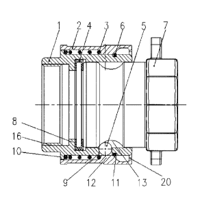
As shown in FIG. 1, the embodiment provides a quick-insertion coupling joint,
which
includes a female coupler body 1, a sliding sleeve 2, elastic elements 3, a
sealing gasket 4,
limiting elements 5 and a retaining ring 6, a socket is arranged in one end of
the female coupler
body 1 and is used for connecting a Camlock male adapter 7, a seal retainer 8
is arranged in an
inner wall of the socket, the sealing gasket 4 is arranged on one surface,
close to a port of the
socket, of the seal retainer 8, multiple limiting holes 9 are
circumferentially arranged in a side
wall of the socket, a limiting element 5 is arranged in each limiting hole 9,
the limiting hole 9 can
limit the limiting element 5 to prevent the limiting element from separating
from the limiting hole
9 inwards, a first boss 10 is arranged on an outer side wall of the female
coupler body 1, the
sliding sleeve 2 sleeves the exterior of the first boss 10, a coupling groove
11 is arranged in the
outer side wall of the female coupler body 1, the coupling groove 11 is
arranged between the port
of the socket and the limiting hole 9, the retaining ring 6 is arranged in the
coupling groove 11, a
second boss 12 is arranged on an inner wall of the sliding sleeve 2, the
second boss 12 is arranged
between the first boss 10 and the retaining ring 6, the internal diameter of
the second boss 12 is
less than the external diameter of the retaining ring 6, the elastic elements
3 sleeve the exterior of
the female coupler body 1 while the elastic elements 3 are arranged between
the second boss 12
and the first boss 10, the elastic elements 3 are in a compression state, and
a limiting groove 13 is
circumferentially arranged in an outer wall of the Camlock male adapter 7.
When the Camlock
4
CA 3061531 2019-11-13
male adapter 7 is inserted into the socket and the second boss 12 slides to
come into contact with
the retaining ring 6, the second boss 12 can ensure that the limiting element
5 is fixed in the
limiting groove 13 and the Camlock male adapter 7 tightly presses the sealing
gasket 4 at the seal
retainer 8; and an end face, away from the first boss 10, of the second boss
12 is inclined to one
end away from the first boss 10, so, when the second boss 12 slides away from
the limiting hole 9,
the limiting element 5 can be disconnected from the limiting groove 13.
When the quick-insertion coupling joint is assembled, the sliding sleeve 2 is
pushed by hand
in order that the second boss 12 is away from the limiting hole 9 and the
limiting element 5 can
move outwards from the limiting hole 9 in a radial direction of the socket and
cannot be
disconnected from the limiting hole 9 under the blocking action of the sliding
sleeve 2, the
Camlock male adapter 7 is inserted into the socket of the female coupler body
1 and extrudes the
sealing gasket 4, the sliding sleeve 2 is loosened, and at this time, the
sliding sleeve 2 moves
towards the limiting hole 9 and extrudes the limiting element 5 under the
elastic action of the
elastic elements 3 such that the limiting element 5 is fixed in the limiting
groove 13 of the
Camlock male adapter 7, thereby preventing the Camlock male adapter 7 from
moving outwards
and achieving quick connection of the joint, so the structure is simple, a
little space is occupied,
and sealing performance of the joint is ensured. When the quick-insertion
coupling joint is
disassembled, the female coupler body 1 is held by hand, the sliding sleeve 2
is pushed in order
that the second boss 12 is away from the limiting hole 9, at this time, the
limiting element 5 is
disconnected from the second boss 12 and moves outwards from the limiting hole
9 in the radial
direction of the socket, and after the limiting element 5 is disconnected from
the limiting groove
13 of the Camlock male adapter 7, the Camlock male adapter 7 and the female
coupler body 1 are
separated, so disassembly is convenient and quick. The quick-insertion
coupling joint provided
by the present invention can replace all kinds of Camlock female couplers, and
its specification
range is from 1/2" to 8", where the material of the female coupler body 1 and
the sliding sleeve 2
can be aluminum alloy, copper alloy, stainless steel, carbon steel, PP and the
like.
As shown in FIG. 4, a rectangular annular groove 15 is arranged in an inner
wall of the
sealing gasket 4; when a fluid is conveyed, a pressure difference is generated
between an interior
of the rectangular annular groove 15 and an exterior thereof, the fluid
extrudes the sealing gasket
4 from the interior of the rectangular annular groove 15 to the exterior
thereof, a seal surface of
the sealing gasket 4 is stressed, the sealing gasket 4 is unlikely to generate
leakage, and within a
certain pressure range, the greater an internal pressure is, the better the
sealing performance is;
one end face 21 of the sealing gasket 4 is inclined outwards, so, when the
internal pressure is low,
the Camlock male adapter 7 extrudes the inclined end face 21 of the sealing
gasket 4 such that the
seal surface of the sealing gasket 4 is in extrusion contact to ensure no
leakage under a low
CA 3061531 2019-11-13
pressure; and an annular boss 19 is arranged in the rectangular annular groove
15 to improve
strength and elasticity of the sealing gasket 4.
As shown in FIG. 5 to FIG. 8, the limiting element 5 is a limiting ball, the
limiting ball is
made of steel so as to be convenient in manufacture and low in costs, the
limiting hole is a step
hole when the limiting element 5 is the limiting ball, the limiting hole 9
includes a first hole 17
and a second hole 18, which are radially arranged, the first hole 17 is close
to the interior in a
radial direction of the second hole 18, the diameter of the first hole 17 is
less than the diameter of
the limiting ball such that the first hole 17 can prevent the limiting ball
from separating from the
limiting hole 9 inwards; however, the limiting element 5 is not limited to the
limiting ball and can
also be a limiting block, the limiting block can be a square limiting block,
the corresponding
limiting hole 9 is also a square limiting hole, the limiting block is arranged
in the limiting hole 9
in a sliding manner, there is a great contact area of a side wall of the
limiting block and an inner
wall of the limiting hole 9 such that stress effect is great, an inclined
surface is respectively
arranged on two sides, in an axial direction of the socket, of one end close
to the interior in a
radial direction of the limiting block such that the Camlock male adapter 7 is
conveniently
inserted into or pulled out of the socket, a limiting bulge 24 is arranged on
one side surface close
to the interior in a radial direction of the limiting hole 9, a coupling bulge
23 is arranged on one
side wall of one end close to the exterior in a radial direction of the
limiting block, and after the
limiting block slides inwards in the radial direction of the limiting hole 9
till the limiting bulge 24
and the coupling bulge 23 are in contact, the limiting bulge 24 can limit the
coupling bulge 23 to
prevent the coupling bulge from continuously sliding inwards.
As shown in FIG. 1, a dust-proof boss 20 is arranged on the inner wall of the
sliding sleeve 2,
the dust-proof boss 20 is arranged at one end, close to the port of the
socket, of the sliding sleeve
2, and the internal diameter of the dust-proof boss 20 is greater than the
external diameter of the
socket such that the dust-proof boss 20 can prevent outside dust from entering
the sliding sleeve
2.
The elastic element 3 is a spring and has a simple structure.
In the embodiment, the seal retainer 8 is a sealing boss, the sealing gasket 4
is arranged on
one surface, close to the port of the socket, of the sealing boss, a
connection port is arranged at
one end, away from the socket, of the female coupler body 1, the connection
port and the socket
are interconnected, and the connection port is used for connecting a pipe
fitting, where an internal
thread 16 is arranged in an inner wall of the connection port, certainly an
external thread can also
be arranged in an outer wall of the connection port, so the connection port is
connected with the
pipe fitting through the thread, which is convenient and has great sealing
performance.
Embodiment 2
6
CA 3061531 2019-11-13
As shown in FIG. 2, the embodiment provides a quick-insertion coupling joint,
and the
difference from the quick-insertion coupling joint in Embodiment 1 lies in:
anti-skid mesh-shaped
bulges 14 are arranged on an outer surface of a sliding sleeve 2 such that
friction between the
sliding sleeve 2 and the hand can be increased and the sliding sleeve 2 is
convenient to be pushed.
Where a connection port for connecting a pipe fitting is a tail pipe 22, and
the quick-insertion
coupling joint is connected with the pipe fitting through the tail pipe 22.
Embodiment 3
As shown in FIG. 3, in a quick-insertion coupling joint provided by the
embodiment, a seal
retainer 8 is a sealing diaphragm, the sealing diaphragm seals one end, away
from a socket, of a
female coupler body, a sealing gasket 4 is arranged on one surface, close to a
port of the socket,
of the sealing diaphragm, and due to arrangement of the sealing diaphragm, a
pipe fitting can be
sealed and dust can be prevented.
Several examples are used for illustration of the principles and
implementation methods of
the present invention. The description of the embodiments is used to help
illustrate the method
and its core principles of the present invention. In addition, those skilled
in the art can make
various modifications in terms of specific embodiments and scope of
application in accordance
with the teachings of the present invention. In conclusion, the content of
this specification shall
not be construed as a limitation to the invention.
7
CA 3061531 2019-11-13