Note: Descriptions are shown in the official language in which they were submitted.
CA 03061698 2019-10-28
- 1 -
Description
Title of Invention
WIRELESS RELAY DEVICE
Technical Field
[0001]
The present invention relates to a radio relay device.
Background Art
[0002]
For example, Patent Literatures 1 and 2 each disclose
a radio relay device for achieving a longer communication
distance in radio communication by allowing a radio wave
transmitted from a source (e.g., a base station) to be
received even at a destination (e.g., a terminal) present at a
place which is less visible (or invisible) from the source.
[0003]
Fig. 1 of Patent Literature 1 illustrates a radio relay
device for allowing radio communication between a base
station and a terminal (a terminal device described in
Patent Literature 1) which are separated from each other by
a wall which transmits therethrough no radio wave. The
radio relay device disclosed in Patent Literature 1 is
configured such that a coupled antenna and a relay antenna
are connected with each other via metal cables (a coaxial
CA 03061698 2019-10-28
- 2 -
cable and a ribbon feeder). According to the radio relay
device disclosed in Patent Literature 1, the metal cables are
provided so as to extend over both sides of the wall, and the
coupled antenna and the relay antenna are provided in a
base station side space and a terminal side space,
respectively, of two spaces which are separated by the wall.
In a case where the coupled antenna is disposed so as to be
coupled with a base antenna of the base station and the
relay antenna is disposed so as to be coupled with the
terminal, the radio relay device disclosed in Patent
Literature 1 allows radio transmission between the base
station and the terminal which are separated by the wall.
[0004]
For example, Fig. 1 of Patent Literature 2 illustrates a
radio relay device for allowing radio communication between
an outdoor base station and an indoor terminal (a terminal
station described in Patent Literature 2). The radio relay
device disclosed in Patent Literature 2 includes two
antennas, two radio circuits, two baseband circuits, two
control sections, and one DPRAM. According to the radio
relay device disclosed in Patent Literature 2, in a case
where one of the antennas receives a radio wave from the
base station, a radio signal superimposed on the radio wave
is converted into a baseband signal with use of one of the
radio circuits first, and then the baseband signal is decoded
,
,
CA 03061698 2019-10-28
- 3 -
into a data signal with use of one of the baseband circuits.
Thereafter, the data signal is encoded into a baseband
signal with use of the other one of the baseband circuits,
the baseband signal is converted into a radio signal with
use of the other one of the radio circuits, and a radio wave
on which the radio signal is superimposed is transmitted to
the terminal via the other one of the antennas. The radio
relay device disclosed in Patent Literature 2 thus can relay
radio communication between the base station and the
terminal.
Citation List
[Patent Literatures]
[0005]
[Patent Literature 1]
Japanese Patent Application Publication Tokukai No.
2002-185381 (Publication Date: June 28, 2002)
[Patent Literature 2]
Japanese Patent Application Publication Tokukai No.
2005-101986 (Publication Date: April 14, 2005)
Summary of Invention
Technical Problem
[0006]
According to the radio relay device disclosed in Patent
Literature 1, in a case where a radio wave to be relayed has
,
,
CA 03061698 2019-10-28
- 4 -
a higher frequency, a greater transmission loss of a radio
wave occurs in the metal cables. Thus, in a case where the
radio relay device disclosed in Patent Literature 1 is applied
to radio communication carried out with use of a microwave
or a millimeter wave, a radio wave may be relayed with
greatly reduced efficiency, or it may be difficult for the base
station and the terminal device to communicate with each
other.
[0007]
The radio relay device disclosed in Patent Literature 2
requires (i) a decoding process for decoding a baseband
signal into a data signal and (ii) an encoding process for
encoding the data signal into a baseband signal. The
decoding process and the encoding process impose a heavy
load on the radio relay device. Thus, the radio relay device
disclosed in Patent Literature 2 has a problem such that a
long time delay occurs in association with radio
communication relay. Furthermore, the decoding process
and the encoding process, which impose a heavy load on the
radio relay device, also lead to an increase in cost of a
circuit (IC) constituting the radio relay device.
(00081
An aspect of the present invention has been made in
view of the problems, and an object of an aspect of the
present invention is to configure a radio relay device, which
CA 03061698 2019-10-28
- 5 -
is applied to radio communication carried out with use of a
microwave or a millimeter wave, such that a time delay
which may occur in association with radio communication
relay is reduced while a transmission loss of a radio wave is
prevented or reduced. Furthermore, a secondary object of an
aspect of the present invention is to prevent or reduce an
increase in cost of a circuit (IC) constituting the radio relay
device.
Solution to Problem
[00091
In order to attain the object, a radio relay device in
accordance with an aspect of the present invention
includes: a substrate; a receiving antenna, provided on the
substrate, for converting a first electromagnetic wave into a
first radio frequency (RF) signal; a first radio integrated
circuit (IC), provided on the substrate, for converting, into a
baseband signal, the first RF signal which has been
obtained via the receiving antenna; a second radio IC,
provided on the substrate, for converting, into a second RF
signal, the baseband signal which has been obtained by the
first radio IC; and a transmitting antenna, provided on the
substrate, for converting, into a second electromagnetic
wave, the second RF signal which has been obtained by the
second radio IC, the first radio IC and the second radio IC
being connected with each other via a wire on the substrate
CA 03061698 2019-10-28
- 6 -
so that the baseband signal is transmitted via the wire.
Advantageous Effects of Invention
(00101
An aspect of the present invention makes it possible
to configure a radio relay device, which is applied to radio
communication carried out with use of a microwave or a
millimeter wave, such that a time delay which may occur in
association with radio communication relay is reduced while
a transmission loss of an electric signal is prevented or
reduced.
Brief Description of Drawings
[0011]
Fig. 1 is a plan view and a side view each
schematically illustrating a configuration of a radio relay
device in accordance with Embodiment 1 of the present
invention.
(a) and (b) of Fig. 2 are each a side view illustrating a
state in which the radio relay device illustrated in Fig. 1 is
bent.
Fig. 3 is a plan view schematically illustrating a
configuration of a radio relay device in accordance with
Embodiment 2 of the present invention.
Fig. 4 is a conceptual diagram showing an example of
use of a radio relay device in accordance with an
CA 03061698 2019-10-28
- 7 -
embodiment of the present invention.
Description of Embodiments
[0012]
Embodiments of the present invention are described
below with reference to Figs. 1 through 4.
[0013]
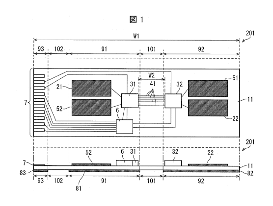
[Embodiment 1]
Fig. 1 is a plan view and a side view (obtained in a
case where the plan view is viewed from bottom to above)
each schematically illustrating a configuration of a radio
relay device 201 in accordance with Embodiment 1 of the
present invention. The radio relay device 201 illustrated in
Fig. 1 includes a substrate 11, receiving antennas 21 and
22, radio ICs 31 and 32, a plurality of wires 41,
transmitting antennas 51 and 52, a control IC 6, an edge
connector 7, and reinforcing plates 81 to 83. The radio relay
device 201 can include, for example, a capacitor (not
illustrated), a resistor (not illustrated), and a quartz
oscillator (not illustrated) which are provided around the
radio IC 31 or the radio IC 32 and each of which is an
electronic component necessary for driving of the radio ICs
31 and 32.
[0014]
The substrate 11 is a substrate on which to mount
CA 03061698 2019-10-28
- 8 -
various members constituting the radio relay device 201.
The substrate 11 is a flexible substrate whose base material
is a liquid crystal polymer (LCP). Since the base material of
the substrate 11 is an LCP, a loss, caused by the substrate
11, in electric signal and/or RF signal can be prevented or
reduced in a case where the radio relay device 201 is used
in radio communication in a several GHz band to several ten
(e.g., 60) GHz band. The substrate 11 has a front surface on
which the receiving antennas 21 and 22, the radio ICs 31
and 32, the plurality of wires 41, the transmitting antennas
51 and 52, the control IC 6, and the edge connector 7 are
provided. The substrate 11 has a back surface on which the
reinforcing plates 81 to 83 are provided. Assume here that a
length of the substrate 11, as measured in a longer side
direction thereof, is Wl. Note that the substrate 11 has a
multilayer structure, though not illustrated. The base
material of the substrate 11 is not limited to an LCP but can
be, for example, a polyimide. Furthermore, the substrate 11,
which is a single plate in Fig. 1, can alternatively be
obtained by combining a plurality of plates.
[0015]
The receiving antennas 21 and 22 are each provided
on the substrate 11 in a form of a pattern made of metal.
The receiving antennas 21 and 22 each receive a first
electromagnetic wave and convert, into a first RF signal, the
CA 03061698 2019-10-28
- 9 -
first electromagnetic wave received. The first RF signal is,
for example, a signal belonging to a millimeter wave band
and having a frequency of 30 GHz to 300 GHz. For simple
illustration, in Fig. 1, the receiving antennas 21 and 22 are
each a member which is rectangular when viewed from
above. Note, however, that neither of the receiving antennas
21 and 22 is particularly limited in shape. Note also that
the receiving antennas 21 and 22 each can be provided on
not only the front surface of the substrate 11 but also the
back surface of the substrate 11 or an inner layer of the
substrate 11.
[00161
The radio ICs 31 and 32 are each mounted on the
substrate 11. The radio IC 31, which is electrically
connected with the receiving antenna 21, demodulates the
first RF signal obtained via the receiving antenna 21 and
converts, into a baseband signal, the first RF signal
demodulated. The radio IC 32, which is electrically
connected with the receiving antenna 22, demodulates the
first RF signal obtained via the receiving antenna 22 and
converts, into a baseband signal, the first RF signal
demodulated. As such a baseband signal, it is possible to
employ, for example, a differential modulated signal having
a frequency of several GHz (e.g., 1 GHz to 3 GHz) and
subjected to IQ modulation.
CA 03061698 2019-10-28
- 10 -
[0017]
The plurality of wires 41 are provided on the
substrate 11. The plurality of wires 41 are each provided in
a form of a pattern made of metal (e.g., copper, copper
plated with nickel, copper plated with gold, or copper plated
with nickel and gold). The radio IC 31 and the radio IC 32
are electrically connected with each other via the plurality
of wires 41, and the baseband signal obtained by the radio
IC 31 and the baseband signal obtained by the radio IC 32
are transmitted via the plurality of wires 41. The plurality of
wires 41 is, for example, a (so-called GSSG) coplanar line in
which a ground, a signal line, a signal line, and a ground
are provided in this order on a substrate or an inner layer of
the substrate. Alternatively, the plurality of wires 41 is, for
example, a plurality of coaxial cables. Either the baseband
signal obtained by the radio IC 31 or the baseband signal
obtained by the radio IC 32 is transmitted via each of the
plurality of wires 41 at a speed of, for example, several GHz
per second. The plurality of wires 41 each have a
characteristic impedance of, for example, 100 0 or 50 0.
Assume here that a length of each of the plurality of wires
41, i.e., a distance between the radio IC 31 and the radio IC
32 is W2.
[0018]
The radio IC 32 modulates the baseband signal
CA 03061698 2019-10-28
- 11 -
obtained by the radio IC 31 and converts, into a second RF
signal, the baseband signal modulated. The radio IC 31
modulates the baseband signal obtained by the radio IC 32
and converts, into a second RF signal, the baseband signal
modulated. Such a second RF signal can have a frequency
identical to or different from a frequency of the first RF
signal, the second RF signal having been converted from the
baseband signal, the baseband signal having been converted
from the first RF signal. By causing the second RF signal
and the first RF signal to have respective different
frequencies, it is possible to alleviate the fear that the first
RF signal and the second RF signal may be received in a
mixed manner.
(0019)
The transmitting antennas 51 and 52 are each
provided on the substrate 11 in a form of a pattern made of
metal. The transmitting antenna 51, which is electrically
connected with the radio IC 32, converts, into a second
electromagnetic wave, the second RF signal obtained by the
radio IC 32 (emits, into a space, the second RF signal
obtained by the radio IC 32). The transmitting antenna 52,
which is electrically connected with the radio IC 31,
converts, into a second electromagnetic wave, the second RF
signal obtained by the radio IC 31. For simple illustration,
in Fig. 1, the transmitting antennas 51 and 52 are each a
CA 03061698 2019-10-28
- 12 -
pattern which is rectangular when viewed from above. Note,
however, that neither of the transmitting antennas 51 and
52 is particularly limited in shape. Note also that the
transmitting antennas 51 and 52 each can be provided on
not only the front surface of the substrate 11 but also the
back surface of the substrate 11 or the inner layer of the
substrate 11.
[0020]
In an operation carried out in a case where the
receiving antenna 21 receives the first electromagnetic
wave, the radio IC 31 corresponds to a "first radio IC"
recited in Claims, and the radio IC 32 corresponds to a
"second radio IC" recited in Claims. In contrast, in an
operation carried out in a case where the receiving antenna
22 receives the first electromagnetic wave, the radio IC 32
corresponds to the "first radio IC" recited in Claims, and the
radio IC 31 corresponds to the "second radio IC" recited in
Claims.
[0021]
The receiving antenna 21 and the transmitting
antenna 51 are preferably directional antennas having
respective different maximum gain directions. Alternatively,
the receiving antenna 21 and the transmitting antenna 51
are preferably directional antennas having respective
adjustable maximum gain directions. This makes it easy to
CA 03061698 2019-10-28
- 13 -
clearly determine (i) an angle at which the receiving antenna
21 receives an electromagnetic wave and (ii) an angle at
which the transmitting antenna 51 transmits an
electromagnetic wave. Similarly, the receiving antenna 22
and the transmitting antenna 52 are preferably directional
antennas having respective different maximum gain
directions. Alternatively, the receiving antenna 22 and the
transmitting antenna 52 are preferably directional antennas
having respective adjustable maximum gain directions. This
makes it easy to clearly determine (i) an angle at which the
receiving antenna 22 receives an electromagnetic wave and
(ii) an angle at which the transmitting antenna 52 transmits
an electromagnetic wave. Examples of a directional antenna
having an adjustable maximum gain direction include a
phased array antenna. According to an array antenna, a
main beam direction of a radiated electromagnetic wave,
which is obtained by superimposing electromagnetic waves
radiated from respective antenna elements, can be changed
by controlling a time delay imparted to an RF signal
supplied to each of the antenna elements. The phased array
antenna is an array antenna having such a beam forming
function.
(00221
The control IC 6 is provided on the substrate 11. The
control IC 6 controls the radio ICs 31 and 32. The control IC
CA 03061698 2019-10-28
- 14 -
6 controls, for example, (i) a frequency of an output signal
of each of the radio ICs 31 and 32 and (ii) a level (electric
power) of the output signal.
[0023]
The edge connector 7 is a connector provided at an
end in the longer side direction of the substrate 11. The
edge connector 7 is connected with the radio ICs 31 and 32
and the control IC 6. It is possible to supply a power supply
voltage to the radio IC 31 from a power source (not
illustrated), provided on an outside of the radio relay device
201, via a terminal of the edge connector 7, which terminal
is connected with the radio IC 31. It is possible to supply a
power supply voltage to the radio IC 32 from the power
source (not illustrated), provided on the outside of the radio
relay device 201, via a terminal of the edge connector 7,
which terminal is connected with the radio IC 32. It is
possible to supply a power supply voltage to the control IC 6
from the power source (not illustrated), provided on the
outside of the radio relay device 201, via a terminal of the
edge connector 7, which terminal is connected with the
control IC 6. Furthermore, it is possible to supply a signal
to the control IC 6 from a signal source (not illustrated),
provided on the outside of the radio relay device 201, via a
terminal of the edge connector 7, which terminal is
connected with the control IC 6. The edge connector 7 is
CA 03061698 2019-10-28
- 15 -
connected with the radio ICs 31 and 32 and the control IC 6
via wires provided on the substrate 11. These wires are
provided on any of layers of the multilayer structure
(described earlier) of the substrate 11. Instead of providing
the edge connector 7 to the substrate 11, it is alternatively
possible to solder, to the substrate 11, a plurality of
terminals constituting a connector.
[0024]
The reinforcing plate 81 is provided so as to extend
over a first side of the substrate 11 which first side is
opposite from a second side of the substrate 11 on which
second side the receiving antenna 21, the radio IC 31, the
transmitting antenna 52, and the control IC 6 are provided.
The reinforcing plate 81 reinforces a region 91 of the
substrate 11 in which region 91 the receiving antenna 21,
the radio IC 31, and the transmitting antenna 52, and the
control IC 6 are provided.
[0025]
The reinforcing plate 82 is provided so as to extend
over the first side of the substrate 11 which first side is
opposite from the second side of the substrate 11 on which
second side the receiving antenna 22, the radio IC 32, and
the transmitting antenna 51 are provided. The reinforcing
plate 82 reinforces a region 92 of the substrate 11 in which
region 92 the receiving antenna 22, the radio IC 32, and the
CA 03061698 2019-10-28
- 16 -
transmitting antenna 51 are provided.
[0026]
The reinforcing plate 83 is provided on the first side
of the substrate 11 which first side is opposite from the
second side of the substrate 11 on which second side the
edge connector 7 is provided. The reinforcing plate 83
reinforces a region 93 of the substrate 11 in which region
93 the edge connector 7 is provided.
[0027]
The reinforcing plates 81 to 83 are so hard as to be
unbendable. The reinforcing plates 81 to 83 each can be
made of, for example, a resinous plate, a metallic plate, or a
metallic solid pattern.
[0028]
In the operation carried out in a case where the
receiving antenna 21 receives the first electromagnetic
wave, the reinforcing plate 81 corresponds to a "first
reinforcing plate" recited in Claims, and the reinforcing
plate 82 corresponds to a "second reinforcing plate" recited
in Claims. In contrast, in the operation carried out in a case
where the receiving antenna 22 receives the first
electromagnetic wave, the reinforcing plate 82 corresponds
to the "first reinforcing plate" recited in Claims, and the
reinforcing plate 81 corresponds to the "second reinforcing
plate" recited in Claims.
CA 03061698 2019-10-28
- 17 -
[00291
According to the radio relay device 201, a baseband
signal having a lower frequency than the first RF signal and
the second RF signal is transmitted via each of the plurality
of wires 41 via which the radio IC 31 and the radio IC 32
are connected with each other. This makes it possible to
prevent or reduce a transmission loss of an electric signal in
the plurality of wires 41. Specifically, the radio relay device
201 can further prevent or reduce an influence of a
transmission loss of an electromagnetic wave than the radio
relay device disclosed in Patent Literature 1. No
electromagnetic wave is transmitted via a part of the
plurality of wires 41 via which part the baseband signal is
transmitted. Thus, in such a case, an apparent
electromagnetic wave loss is further prevented or reduced in
the radio relay device 201 than in a case where an
electromagnetic wave is transmitted via the part of the
plurality of wires 41 via which part the baseband signal is
transmitted.
[0030]
According to the radio relay device 201, the radio IC
31 does not need to carry out a decoding process for
decoding the first RF signal into a radio signal, and the
radio IC 32 does not need to carry out an encoding process
for encoding the radio signal again into the second RF
CA 03061698 2019-10-28
- 18 -
signal. Thus, as compared with the radio relay device
disclosed in Patent Literature 2, the radio relay device 201
makes it possible to further reduce a time delay which may
occur in association with radio communication relay. Since
the radio IC 31 and the radio IC 32 do not need to carry out
the decoding process and the encoding process,
respectively, it is possible to reduce a load on each of the
radio IC 31 and the radio IC 32. This allows the radio relay
device 201 to reduce cost of the radio IC 31 and the radio IC
32.
100311
As described above, the radio relay device 201 which
is operated with use of a microwave or a millimeter wave
can achieve a reduction in time delay, which may occur in
association with radio communication relay, while
preventing or reducing a transmission loss of a radio wave.
[0032]
(a) and (b) of Fig. 2 are each a side view illustrating a
state in which the radio relay device 201 is bent.
[0033]
The substrate 11 is a flexible substrate as described
earlier. Thus, it is possible to easily bend regions of the
substrate 11, which regions are different from the regions
91 to 93, whereas it is difficult to bend the regions 91 to 93.
That is, it is possible to bend the substrate 11 so as to
CA 03061698 2019-10-28
- 19 -
cause a ridge in each of (i) a region 101 located between the
reinforcing plate 81 (corresponding to the region 91) and the
reinforcing plate 82 (corresponding to the region 92) and (ii)
a region 102 located between the reinforcing plate 81 and
the reinforcing plate 83 (corresponding to the region 93).
[0034]
In (a) of Fig. 2, the substrate 11 is bent at an angle of
90 in the region 101 in which the ridge is caused. With the
configuration, a direction in which the receiving antenna 21
and the transmitting antenna 52 face and a direction in
which the receiving antenna 22 and the transmitting
antenna 51 face differ from each other by 90 . In this case,
the first electromagnetic wave received by the receiving
antenna 21 is bent at 90 by the radio relay device 201 and
then transmitted from the transmitting antenna 51 in a
form of the second electromagnetic wave. In this case,
similarly, the first electromagnetic wave received by the
receiving antenna 22 is bent at 90 by the radio relay device
201 and then transmitted from the transmitting antenna 52
in the form of the second electromagnetic wave.
[0035]
In (b) of Fig. 2, the substrate 11 is bent at an angle of
180 in the region 101 in which the ridge is caused. With
the configuration, a direction in which the receiving
antenna 21 and the transmitting antenna 52 face and a
CA 03061698 2019-10-28
- 20 -
direction in which the receiving antenna 22 and the
transmitting antenna 51 face differ from each other by 1800
.
In this case, the first electromagnetic wave received by the
receiving antenna 21 is transmitted from the transmitting
antenna 51 in the form of the second electromagnetic wave
without being bent by the radio relay device 201. In this
case, similarly, the first electromagnetic wave received by
the receiving antenna 22 is transmitted from the
transmitting antenna 52 in the form of the second
electromagnetic wave without being bent by the radio relay
device 201.
[0036]
The radio relay device 201 easily allows a direction of
a normal to the region 91 in which the receiving antenna 21
is provided and a direction of a normal to the region 92 in
which the transmitting antenna 51 is provided to differ from
each other. Thus, the radio relay device 201 easily allows a
maximum gain direction of the receiving antenna 21 and a
maximum gain direction of the transmitting antenna 51 to
be adjusted to respective any directions. Note that the
substrate 11 can alternatively be bent at an angle different
from 90 or 180 in the region 101 in which the ridge is
caused.
[0037]
Furthermore, the reinforcing plate 81 makes it
CA 03061698 2019-10-28
- 21 -
possible to prevent parts of the substrate 11 which parts
are located directly below the receiving antenna 21, the
radio IC 31, the transmitting antenna 52, and the control IC
6, respectively, from being bent. Moreover, the reinforcing
plate 82 makes it possible to prevent parts of the substrate
11 which parts are located directly below the receiving
antenna 22, the radio IC 32, and the transmitting antenna
51, respectively, from being bent. This makes it possible to
prevent characteristics of the receiving antennas 21 and 22,
characteristics of the radio ICs 31 and 32, characteristics of
the transmitting antennas 51 and 52, and characteristics of
the control IC 6 from being unexpectedly changed by
bending of the substrate 11. Further, the reinforcing plate
83 makes it possible to prevent a part of the substrate 11
which part is located directly below the edge connector 7
from being bent.
[0038]
Note that an angle at which to bend the substrate 11
in the region 102 in which the ridge is caused can also be
arbitrarily set. This makes it possible to freely change a
direction of the edge connector 7, so that a wire, for
example can be more freely connected to the edge connector
7.
[0039]
In order to protect the radio relay device 201 and
CA 03061698 2019-10-28
- 22 -
reduce the fear that memory of the shape of the radio relay
device 201 which has been bent as described earlier may be
suppressed, it is preferable to use the radio relay device 201
which is held in, for example, a resinous clamshell case (not
illustrated). In this case, the above case preferably has an
opening provided on a path for the first electromagnetic
wave, or is preferably made of a material which easily
transmits therethrough an electromagnetic wave having a
wavelength of the first electromagnetic wave. Same applies
to the second electromagnetic wave.
[0040]
Furthermore, in order to retain memory of the shape
of the radio relay device 201 which has been bent as
described earlier, it is possible to, for example, attach, to a
back surface of the radio relay device 201, a jig (not
illustrated) having a desired shape.
[0041]
Moreover, in order to achieve an electromagnetic
shield and/or mechanical reinforcement, it is possible to
cover, by a metallic cover (not illustrated), the radio ICs 31
and 32, the control IC 6, and an area around the radio ICs
31 and 32 and the control IC 6.
[0042]
Embodiment 2
Fig. 3 is a plan view schematically illustrating a
CA 03061698 2019-10-28
- 23 -
configuration of a radio relay device 202 in accordance with
Embodiment 2 of the present invention. Note that, for
convenience, members having functions identical to those of
the respective members described in Embodiment 1 are
given respective identical reference signs, and a description
of those members is omitted here.
[0043]
The radio relay device 202 illustrated in Fig. 3 differs
from the radio relay device 201 Fig. 1 in that the radio relay
device 202 is configured to include a substrate 12 instead of
the substrate 11 and include a plurality of wires 42 instead
of the plurality of wires 41. The substrate 12 and the
plurality of wires 42 are identical in function to the
substrate 11 and the plurality of wires 41, respectively,
except for the points described below.
[0044]
W3, which is a length of the substrate 12, as
measured in a longer side direction thereof, is longer than
Wl, which is the length of the substrate 11, as measured in
the longer side direction thereof. W4, which is a length of
each of the plurality of wires 42 of the substrate 12, is
longer than W2, which is the length of each of the plurality
of wires 41 of the substrate 11.
[0045]
A distance between a receiving antenna 21 and a
CA 03061698 2019-10-28
- 24 -
transmitting antenna 51 and a distance between a receiving
antenna 22 and a transmitting antenna 52 are longer in the
radio relay device 202 than in the radio relay device 201.
[0046]
Note that it is difficult for an electromagnetic wave
having a frequency in a millimeter wave band to be
transmitted through a wall and a door. Thus, for example,
in order for (i) a base station provided in a corridor and (ii)
at least one terminal device provided in a room to
communicate with each other over a wall or a door with use
of an electromagnetic wave having a frequency in a
millimeter wave band, it is necessary to relay the
electromagnetic wave. For example, the radio relay device
202 which is provided so as to pass through a space above
the door can relay an electromagnetic wave between the
base station (corridor side) and the at least one terminal
device (room side). That is, the radio relay device 202 is
useful for the base station and the at least one terminal
device to communicate with each other over the wall or the
door. Furthermore, in a case where the at least one terminal
device is a single fixed terminal device, each antenna
provided on the terminal device side of the radio relay
device 202 is preferably an antenna which is highly
directional and faces toward the terminal device. In
contrast, in a case where the at least one terminal device
CA 03061698 2019-10-28
- 25 -
comprises a plurality of terminal devices or includes a
mobile terminal device, each antenna provided on the
terminal device side of the radio relay device 202 is
preferably an antenna which is moderately directional.
[0047]
According to the radio relay device 202, the length W4
can be made longer in accordance with a purpose for which
the radio relay device 202 is used. Note, however, that
attention should be paid because the length W4 which is too
long causes an electric signal to be greatly attenuated in
each of the plurality of wires 42. In a case where a base
material of the substrate 12 is a polyimide and a baseband
signal of 3 GHz is transmitted via, for example, a microstrip
line, a transmission loss of 2 dB to 3 dB occurs per 10 cm.
As compared with the substrate 12 whose base material is a
polyimide, the substrate 12 whose base material is an LCP
makes it possible to achieve a wire in which a transmission
loss is smaller. This is because the substrate 12 whose base
material is an LOP has a smaller dielectric constant and a
smaller dielectric dissipation factor than the substrate 12
whose base material is a polyimide.
[0048]
[Example of use]
Fig. 4 is a conceptual diagram showing an example of
use of a radio relay device 20 in accordance with an
CA 03061698 2019-10-28
- 26 -
embodiment of the present invention.
[0049]
The radio relay device 20 relays an electromagnetic
wave between a radio master unit 111 and a radio slave unit
112. The radio relay device 20 can be the radio relay device
201 illustrated in Fig. 1 or the radio relay device 202
illustrated in Fig. 3.
[0050]
The radio master unit 111 and the radio slave unit
112 have respective functions of being capable of
communicating with each other via an electromagnetic wave
having a frequency in, for example, a millimeter wave band.
Note, however, that in Fig. 4, the radio master unit 111 and
the radio slave unit 112 are provided in a positional
relationship in which due to presence of buildings 121 to
124, in particular, presence of the building 121, an
electromagnetic wave emitted by one of the radio master
unit 111 and the radio slave unit 112 does not reach the
other one of the radio master unit 111 and the radio slave
unit 112 in a case where the radio relay device 20 is not
used.
[0051]
The radio relay device 20 guides a first
electromagnetic wave, which is an electromagnetic wave
emitted by one of the radio master unit 111 and the radio
CA 03061698 2019-10-28
- 27 -
slave unit 112, to the other one of the radio master unit 111
and the radio slave unit 112 in a form of a second
electromagnetic wave. This allows the radio relay device 20
to relay an electromagnetic wave between the radio master
unit 111 and the radio slave unit 112.
[0052]
Aspects of the present invention can also be
expressed as follows:
A radio relay device (201, 202) in accordance with an
aspect of the present invention includes: a substrate (11,
12); a receiving antenna (21, 22), provided on the substrate
(11, 12) , for converting a first electromagnetic wave into a
first radio frequency (RF) signal; a first radio integrated
circuit (IC) (31, 32), provided on the substrate (11, 12), for
converting, into a baseband signal, the first RF signal which
has been obtained via the receiving antenna (21, 22); a
second radio IC (32, 31), provided on the substrate (11, 22),
for converting, into a second RF signal, the baseband signal
which has been obtained by the first radio IC (31, 32); and a
transmitting antenna (51, 52), provided on the substrate
(11, 12), for converting, into a second electromagnetic wave,
the second RF signal which has been obtained by the second
radio IC (32, 31), the first radio IC (31, 32) and the second
radio IC (32, 31) being connected with each other via a wire
(41, 42) on the substrate (11, 12) so that the baseband
CA 03061698 2019-10-28
- 28 -
signal is transmitted via the wire (41, 42).
[00531
With the configuration, a baseband signal having a
lower frequency than the first RF signal and the second RF
signal is transmitted via the wire via which the first radio IC
and the second radio IC are connected with each other.
Thus, the radio relay device which is applied to radio
communication carried out with use of a microwave or a
millimeter wave can further prevent or reduce a
transmission loss of an electromagnetic wave in the wire
than the radio relay device disclosed in Patent Literature 1.
[0054]
Furthermore, with the configuration, the first radio IC
does not need to carry out a decoding process for decoding
the first RF signal into a data signal, and the second radio
IC does not need to carry out an encoding process for
encoding the data signal into the second RF signal. Thus, as
compared with the radio relay device disclosed in Patent
Literature 2, the radio relay device in accordance with an
aspect of the present invention makes it possible to further
reduce a time delay which may occur in association with
radio communication relay. Since the first radio IC and the
second radio IC do not need to carry out the decoding
process and the encoding process, respectively, it is
possible to reduce a load on each of the first radio IC and
CA 03061698 2019-10-28
- 29 -
the second radio IC, and consequently to reduce cost of the
first radio IC and the second radio IC.
[0055]
As described earlier, according to the present radio
relay device which is applied to radio communication
carried out with use of a microwave or a millimeter wave, a
time delay which may occur in association with radio
communication relay can be reduced while a transmission
loss of a radio wave is prevented or reduced.
[0056]
The radio relay device (201, 202) in accordance with
an aspect of the present invention is preferably configured
such that the substrate (11, 12) is a flexible substrate and
is bent so that the receiving antenna (21, 22) and the
transmitting antenna (51, 52) face in respective different
directions.
[0057]
With the configuration, a receiving antenna and a
transmitting antenna can have respective different
maximum gain directions. This easily allows a maximum
gain direction of the receiving antenna and a maximum gain
direction of the transmitting antenna to be adjusted to
respective any directions.
(0058)
A radio relay device (201, 202) in accordance with an
CA 03061698 2019-10-28
- 30 -
aspect of the present invention is preferably configured to
further include: a first reinforcing plate (81, 82) which
reinforces a first region of the substrate (11, 12) in which
first region the receiving antenna (21, 22) and the first radio
IC (31, 32) are provided; and a second reinforcing plate (82,
81) which reinforces a second region of the substrate (11,
12) in which second region the transmitting antenna (51,
52) and the second radio IC (32, 31) are provided, the
substrate (11, 22) being bent so as to cause a ridge between
the first reinforcing plate (81, 82) and the second
reinforcing plate (82, 81).
[0059]
The configuration makes it possible to prevent parts
of the substrate which parts are located directly below the
receiving antenna, the first radio IC, the transmitting
antenna, and the second radio IC, respectively, from being
bent. Thus, it is possible to prevent characteristics of the
receiving antenna, characteristics of the first radio IC,
characteristics of the transmitting antenna, and
characteristics of the second radio IC from being made
unstable by a stress which occurs in association with
bending of the substrate.
[0060]
The radio relay device in accordance with an aspect of
the present invention is preferably configured such that the
CA 03061698 2019-10-28
- 31 -
receiving antenna (21, 22) and the transmitting antenna
(51, 52) are directional antennas having respective different
maximum gain directions.
[0061]
With the configuration, in a case where (i) a relative
positional relationship between a radio relay device and a
base station and (ii) a relative positional relationship
between the radio relay device and a terminal are
determined in advance, radio communication between the
base station and the terminal can be carried out with higher
efficiency by providing the radio relay device so that a
receiving antenna has a maximum gain direction facing the
base station and a transmitting antenna has a maximum
gain direction facing the terminal.
[0062]
The radio relay device (201, 202) in accordance with
an aspect of the present invention is preferably configured
such that the receiving antenna (21, 22) and the
transmitting antenna (51, 52) are directional antennas
having respective adjustable maximum gain directions.
[0063]
With the configuration, also in a case where (i) a
relative positional relationship between a radio relay device
and a base station and/or (ii) a relative positional
relationship between the radio relay device and a terminal
CA 03061698 2019-10-28
- 32 -
are/is changed after the radio relay device is provided, a
maximum gain direction of a receiving antenna can be easily
adjusted so as to face the base station, and a maximum
gain direction of a transmitting antenna can be easily
adjusted so as to face the terminal.
[0064]
The radio relay device (201, 202) in accordance with
an aspect of the present invention is preferably configured
such that a base material of the substrate (11, 12) is a
liquid crystal polymer.
[0065]
A transmission path constituted by a wire which is
provided on a surface or an inner layer of a liquid crystal
polymer makes it possible to prevent or reduce, in a resin
material, a transmission loss which occurs during
transmission of an electric signal having a frequency in the
range of several GHz to several ten GHz. Furthermore, in a
case where a radio relay device which is applied to radio
communication carried out with use of a millimeter wave
band (e.g., a 60 GHz band), a baseband signal preferably
has a frequency of approximately several GHz. Thus, with
the configuration, the radio relay device in accordance with
an aspect of the present invention can be suitably used for
radio communication carried out with use of a millimeter
wave band (e.g., a 60 GHz band).
CA 03061698 2019-10-28
- 33 -
[0066]
The present invention is not limited to the
embodiments, but can be altered by a skilled person in the
art within the scope of the claims. The present invention
also encompasses, in its technical scope, any embodiment
derived by combining technical means disclosed in differing
embodiments.
Reference Signs List
[0067]
11, 12 Substrate
21, 22 Receiving antenna
31, 32 Radio IC (first radio IC (second radio IC),
second radio IC (first radio IC))
41, 42 Wire
51, 52 Transmitting antenna
81, 82 Reinforcing plate (first reinforcing plate
(second reinforcing plate), second reinforcing plate (first
reinforcing plate))
83 Reinforcing plate
20, 201, 202 Radio relay device