Note: Descriptions are shown in the official language in which they were submitted.
CA 03062327 2019-11-01
WO 2018/204860 PCT/US2018/031213
HEAT TRANSFER COMPOSITIONS, METHODS AND SYSTEMS
Cross Reference to Related Application
The present application claims the priority of U.S. Provisional Application
No. 62/502,406,
filed May 5, 2017, the entirety of which is herein incorporated by reference.
Field of the Invention
The present invention relates to compositions, methods and systems having
utility in heat
exchange systems, including heat pump, air conditioning and refrigeration
applications and
in particular aspects to compositions in heat transfer systems of the type in
which the
refrigerant R-410A would have been used, that is for replacement of the
refrigerant R-410A
for heating and cooling applications and to retrofitting heat exchange
systems, including
systems designed for use with R-410A.
Background
Mechanical refrigeration systems, and related heat transfer devices, such as
heat pumps
and air conditioners, using refrigerant liquids are well known in the art for
industrial,
commercial and domestic uses. Chlorofluorocarbons (CFCs) were developed in the
1930s
as refrigerants for such systems. However, since the 1980s, the effect of CFCs
on the
stratospheric ozone layer has become the focus of much attention. In 1987, a
number of
governments signed the Montreal Protocol to protect the global environment,
setting forth a
timetable for phasing out the CFC products. CFCs were replaced with more
environmentally acceptable materials that contain hydrogen, namely the
hydrochlorofluorocarbons (HCFCs).
One of the most commonly used hydrochlorofluorocarbon refrigerants was
chlorodifluoromethane (HCFC-22). However, subsequent amendments to the
Montreal
protocol accelerated the phase out of the CFCs and also scheduled the phase-
out of
HCFCs, including HCFC-22.
In response to the requirement for a non-flammable, non-toxic alternative to
the CFCs and
HCFCs, industry has developed a number of hydrofluorocarbons (HFCs) which have
zero
ozone depletion potential. R-410A (a 50:50 w/w blend of difluoromethane (HFC-
32) and
pentafluoroethane (HFC-125)) was adopted as the industry replacement for HCFC-
22 in air
1
CA 03062327 2019-11-01
WO 2018/204860 PCT/US2018/031213
conditioning and chiller applications as it does not contribute to ozone
depletion. However,
R-410A is not a drop-in replacement for R22. Thus, the replacement of R-22
with R-410A
required the redesign of major components within heat exchange systems,
including the
replacement and redesign of the compressor to accommodate the higher operating
pressure and volumetric capacity of R-410A, when compared with R-22.
While R-410A has a more acceptable Ozone Depleting Potential (ODP) than R-22,
the
continued use of R-410A is problematic, due to its high Global Warming
Potential of 2088.
There is therefore a need in the art for the replacement of R-410A with a more
environmentally acceptable alternative.
It is understood in the art that it is highly desirable for any replacement
heat transfer fluid to
possess a mosaic of properties including excellent heat transfer properties,
and in particular
heat transfer properties that are well matched to the needs of the particular
application,
chemical stability, low or no toxicity, non-flammability, lubricant
compatibility and/or lubricant
miscibility amongst others. In addition, any replacement for R-410A would
ideally be a good
match for the operating conditions of R-410A in order to avoid modification or
redesign of
the system. The identification of a heat transfer fluid meeting all of these
requirements,
many of which are unpredictable, is is a significant challenge.
With regard to efficiency and use, it is important to note that a loss of
refrigerant
thermodynamic performance or energy efficiency may result in an increase in
fossil fuel
usage as a result of the increased demand for electrical energy. The use of
such a
refrigerant will therefore have a negative secondary environmental impact.
Flammability is considered to be an important, and in some cases, a critical
property for
many heat transfer applications Thus, it is frequently beneficial to use
compounds in such
compositions to achieve, if possible a refrigerant, which is non-flammable. As
used herein,
the term "non-flammable" refers to compounds or compositions which are
determined to be
non-flammable in accordance with ASTM standard E-681-2001 at conditions
described in
ASHRAE Standard 34-2013 and described in Appendix B1 to ASHRAE Standard 34-
2013.
It is critical for maintenance of system efficiency, and proper and reliable
functioning of the
compressor, that lubricant circulating in a vapour compression heat transfer
system is
2
CA 03062327 2019-11-01
WO 2018/204860 PCT/US2018/031213
returned to the compressor to perform its intended lubricating function.
Otherwise, lubricant
might accumulate and become lodged in the coils and piping of the system,
including in the
heat transfer components. Furthermore, when lubricant accumulates on the inner
surfaces
of the evaporator, it lowers the heat exchange efficiency of the evaporator,
and thereby
reduces the efficiency of the system.
R410A is currently used with polyol ester (POE) lubricating oil in air
conditioning
applications, as R410A is miscible with POE at temperatures experienced during
use of
such systems. However, R410A is immiscible with POE at temperatures typically
experienced during operation of low temperature refrigeration systems, and
heat pump
systems. Therefore, unless steps are taken to mitigate against this
immisicibility, POE and
R410A cannot be used in low temperature refrigeration or heat pump systems.
It is therefore desirable to be able to use compositions which are capable of
being used as a
replacement for R410A in heat pump and low temperature refrigeration systems,
but which
do not suffer the drawback of immiscibility with POE at temperatures
experienced during
operation of these systems.
Summary
The present invention provides a refrigerant composition which can be used as
replacements for R-410A and which exhibit the desired mosaic of properties of
excellent
heat transfer properties, chemical stability, low or no toxicity, non-
flammability, lubricant
compatibility and/or lubricant miscibility in combination with an acceptable
Global Warming
.. Potential (GWP) and near zero ODP.
The present invention also includes refrigerants consisting essentially of:
about 38% by weight difluoromethane (HFC-32),
from 57% to 59% by weight trifluoroiodomethane (0F3I); and
.. from 2% to 5% by weight of 002. The refrigerant according to this paragraph
is sometimes
referred to herein for convenience as Refrigerant 1.
The present invention also includes refrigerants consisting essentially of:
about 38% by weight difluoromethane (HFC-32),
3
CA 03062327 2019-11-01
WO 2018/204860 PCT/US2018/031213
from 57% to 59% by weight trifluoroiodomethane (0F3I); and
from 2% to 5% by weight of 002, wherein the refrigerant in non-flammable. The
refrigerant
according to this paragraph is sometimes referred to herein for convenience as
Refrigerant
2.
The present invention also includes refrigerants consisting of:
about 38% by weight difluoromethane (HFC-32),
from 57% to 59% by weight trifluoroiodomethane (0F3I); and
from 2% to 5% by weight of 002. The refrigerant according to this paragraph is
sometimes
referred to herein for convenience as Refrigerant 3.
The present invention also includes refrigerants consisting of:
about 38% by weight difluoromethane (HFC-32),
from 57% to 59% by weight trifluoroiodomethane (0F3I); and
from 2% to 5% by weight of 002, wherein the refrigerant in non-flammable. The
refrigerant
according to this paragraph is sometimes referred to herein for convenience as
Refrigerant
4.
The present invention also includes refrigerants consisting essentially of:
about 38% by weight difluoromethane (HFC-32),
from 58% +/- 0.5 % to 59% +/-0.5% by weight trifluoroiodomethane (0F3I); and
from 2% to 3.5% by weight of 002. The refrigerant according to this paragraph
is
sometimes referred to herein for convenience as Refrigerant 5.
The present invention also includes refrigerants consisting of:
about 38% by weight difluoromethane (HFC-32),
from 58% +/- 0.5 % to 59% +/-0.5% by weight trifluoroiodomethane (0F3I); and
from 2% to 3.5% by weight of 002. The refrigerant according to this paragraph
is
sometimes referred to herein for convenience as Refrigerant 6.
The present invention also includes refrigerants consisting essentially of:
38% +/- 0.5% by weight difluoromethane (HFC-32),
59% +/- 0.5 % by weight trifluoroiodomethane (0F3I); and
4
CA 03062327 2019-11-01
WO 2018/204860 PCT/US2018/031213
3% +/- 0.5 % by weight of 002. The refrigerant according to this paragraph is
sometimes
referred to herein for convenience as Refrigerant 7.
The present invention also includes refrigerants consisting of:
38% +/- 0.5% by weight difluoromethane (HFC-32),
59% +/- 0.5 % by weight trifluoroiodomethane (0F3I); and
3% +/- 0.5 % by weight of 002. The refrigerant according to this paragraph is
sometimes
referred to herein for convenience as Refrigerant 8.
The present invention includes refrigerants consisting essentially of:
from about 34% by weight to about 38% by weight difluoromethane (HFC-32), and
from about 62% by weight to about 66% by weight trifluoroiodomethane (0F31).
The
refrigerant according to this paragraph is sometimes referred to herein for
convenience as
Refrigerant 9.
The present invention includes refrigerants consisting essentially of:
from about 34% by weight to about 38% by weight difluoromethane (HFC-32), and
from about 62% by weight to about 66% by weight trifluoroiodomethane (0F3I),
wherein the
refrigerant in non-flammable. The refrigerant according to this paragraph is
sometimes
referred to herein for convenience as Refrigerant 10.
Preferably, the refrigerant consists of:
from about 34% by weight to about 38% by weight difluoromethane (HFC-32), and
from about 62% by weight to about 66% by weight trifluoroiodomethane (0F31).
The
refrigerant according to this paragraph is sometimes referred to herein for
convenience as
Refrigerant 11.
According to the present invention, there is provided a refrigerant consisting
essentially of:
about 36% by weight difluoromethane (HFC-32), and
about 64% by weight trifluoroiodomethane (0F31). The refrigerant according to
this
paragraph is sometimes referred to herein for convenience as Refrigerant 12.
Preferably, the refrigerant consists of:
about 36% by weight difluoromethane (HFC-32), and
5
CA 03062327 2019-11-01
WO 2018/204860 PCT/US2018/031213
about 64% by weight trifluoroiodomethane (0F31). The refrigerant according to
this
paragraph is sometimes referred to herein for convenience as Refrigerant 13.
It will be appreciated that the term "consists of" means that the refrigerant
contains the three
components HFC-32and 0F31 in the indicated amounts and excludes the presence
of other
components in amounts greater than trace or contamination levels.
As used herein with respect to weight percentages, the term "about" with
respect to an
amount of an identified component means the amount of the identified component
can vary
by an amount of +/- 1% by weight. The refrigerants and compositions of the
invention
include in preferred embodiments amounts of an identified compound or
component
specficied as being "about" wherein the amount is the identified amount +/-
0.5% by weight,
or +/- 0.3% by weight.
Brief Description of the Figure
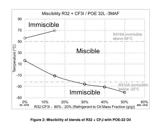
Figure 1 is a miscibility chart illustrating the results of Example 7.
Figure 2 is a miscibility chart illustrating the results of Example 7.
Figure 3 is a miscibility chart illustrating the results of Example 10.
Figure 4 is a miscibility chart illustrating the results of Example 13.
Detailed Description
Applicants have found that the refrigerants of the present invention,
including Refrigerants 1
¨ 13 as described herein, are capable of providing exceptionally advantageous
properties
and in particular non-flammability, especially with the use of the refrigerant
of the present
invention as a replacement for R-410A.
6
CA 03062327 2019-11-01
WO 2018/204860 PCT/US2018/031213
A particular advantage of the refrigerants of the present invention is that
they are non-
flammable when tested in accordance with ASTM E681-2009 test procedure as
required in
ASHRAE Standard 34-2013 and described in Appendix B1 to ASHRAE Standard 34-
2013.
Flammability is defined as the ability of a composition to ignite and/or
propagate a flame. It
will be appreciated by the skilled person that the flammability of a
refrigerant is an important
characteristic for use in many commercially important heat transfer
applications. Thus, it is
a desire in the art to provide a refrigerant composition which can be used as
a replacement
for R-410A which has excellent heat transfer properties, chemical stability,
low or no toxicity,
lubricant compatibility and/or lubricant miscibility and which maintains non
flammability in
use. This requirement is met by the refrigerants of the present invention.
Each of the refrigerants of the present invention, including Refrigerants 1 ¨
13, can be
incorporated into a heat transfer composition. Thus, the invention further
relates to a heat
transfer composition comprising a refrigerant a refrigerant of the present
invention, including
each of Refrigerants 1 ¨13.
is Preferably, the heat transfer composition comprises any of the
refrigerants of the present
invention, including Refrigerants 1 ¨ 13, in an amount of greater than about
40% by weight
of the heat transfer composition or greater than about 50% by weight of the
heat transfer
composition, or greater than about 70% by weight of the heat transfer
composition, or
greater than about 80% by weight of the heat transfer composition or greater
than about
90% by weight of the heat transfer composition, or greater than about 95% by
weight of the
heat transfer composition, or greater than about 97.5% by weight of the heat
transfer
composition. The heat transfer composition may consist essentially of the
refrigerant.
The heat transfer composition of the invention may include other components
for the
purpose of enhancing or providing certain functionality to the composition.
Such other
components or additives may include one or more of lubricants, dyes,
solubilizing agents,
compatibilizers, stabilizers, antioxidants, corrosion inhibitors, extreme
pressure additives
and anti wear additives.
Stabilizers
The heat transfer composition of the invention particularly comprises any of
the refrigerants
as discussed herein, including Refrigerants 1 ¨13, and a stabilizer. Examples
of preferred
stabilizers include diene-based compounds and/or phenol-based compounds and/or
phosphorus compounds and/or nitrogen compounds and/or epoxides selected from
the
7
CA 03062327 2019-11-01
WO 2018/204860 PCT/US2018/031213
group consisting of aromatic epoxides, alkyl epoxides, alkyenyl epoxides.
The diene-based compounds include 03 to 015 dienes and to compounds formed by
reaction of any two or more 03 to 04 dienes. Preferably, the diene based
compounds are
selected from the group consisting of allyl ethers, propadiene, butadiene,
isoprene and
terpenes. The diene-based compounds are preferably terpenes, which include but
are not
limited to terebene, retinal, geranoil, terpinene, delta-3 carene,
terpinolene, phellandrene,
fenchene, myrcene, farnesene, pinene, nerol, citral, camphor, menthol,
limonene, nerolidol,
phytol, carnosic acid and vitamin Al. Preferably, the stabilizer is farnesene.
Preferred terpene stabilizers are disclosed in US Provisional Patent
Application No.
60/638,003 filed on December 12, 2004, which is incorporated herein by
reference.
The stabilizer preferably is provided in the heat transfer composition in an
amount of greater
than 0 and preferably from 0.0001% by weight to about 5% by weight, preferably
0.01% by
weight to about 2% by weight, and more preferably from 0.1 to about 1% by
weight. In each
case, percentage by weight refers to the weight of the heat transfer
composition.
The diene based compounds can be provided in the heat transfer composition in
an amount
of from about 0.001% by weight to about 5 % by weight, preferably about 0.01%
by weight
to about 2% by weight, more preferably from about 0.1 to 1% by weight. In each
case, by
weight refers to the weight of the heat transfer composition.
The diene based compounds are preferably provided in combination with a
phosphorous
compound.
The phosphorus compound can be a phosphite or a phosphate compound. For the
purposes of this invention, the phosphite compound can be a diary!, dialkyl,
triaryl and/or
trialkyl phosphite, in particular one or more compounds selected from hindered
phosphites,
tris-(di-tert-butylphenyl)phosphite, di-n-octyl phophite, iso-decyl diphenyl
phosphite and
diphenyl phosphite, particularly diphenyl phosphite.
8
CA 03062327 2019-11-01
WO 2018/204860 PCT/US2018/031213
The phosphate compounds can be a triaryl phosphate, trialkyl phosphate, alkyl
mono acid
phosphate, aryl diacid phosphate, amine phosphate, preferably triaryl
phosphate and/or a
trialkyl phosphate, particularly tri-n-butyl phosphate.
The phosphorus compounds can be provided in the heat transfer composition in
an amount
of from about 0.001% by weight to about 5 % by weight, preferably about 0.01%
by weight
to about 2% by weight, more preferably from about 0.1 to 1% by weight. In each
case, by
weight refers to weight of the heat transfer composition.
Thus, the heat transfer composition of the invention comprises any of the
refrigerants of the
present invention, including Refrigerants 1 ¨ 13, and a stabilizer composition
comprising a
terpene and a phosphorus compound selected from a phosphate or a phosphite,
particularly, a stabilizer composition comprising a terpene and a phosphite.
For the
purposes of convenience, a stabilizer comprising a terpene and a phosphorus
compound
selected from a phosphate or a phosphite is sometimes referred to for
convenience herein
as Stabilizer 1. For the purposes of convenience, a stabilizer comprising a
terpene and a
phosphite is sometimes referred to for convenience herein as Stabilizer 1A.
The heat transfer composition of the invention can preferably comprise
Refrigerant 1 and
Stabilizer 1 or Stabilizer 1A.
The heat transfer composition of the invention can preferably comprise
Refrigerant 2 and
Stabilizer 1 or Stabilizer 1A.
The heat transfer composition of the invention can preferably comprise
Refrigerant 3 and
Stabilizer 1 or Stabilizer 1A.
The heat transfer composition of the invention can preferably comprise
Refrigerant 4 and
Stabilizer 1 or Stabilizer 1A.
The heat transfer composition of the invention can preferably comprise
Refrigerant 5 and
Stabilizer 1 or Stabilizer 1A.
The heat transfer composition of the invention can preferably comprise
Refrigerant 6 and
Stabilizer 1 or Stabilizer 1A.
The heat transfer composition of the invention can preferably comprise
Refrigerant 7 and
Stabilizer 1 or Stabilizer 1A.
9
CA 03062327 2019-11-01
WO 2018/204860 PCT/US2018/031213
The heat transfer composition of the invention can preferably comprise
Refrigerant 8 and
Stabilizer 1 or Stabilizer 1A.
The heat transfer composition of the invention can preferably comprise
Refrigerant 9 and
Stabilizer 1 or Stabilizer 1A.
The heat transfer composition of the invention can preferably comprise
Refrigerant 10 and
Stabilizer 1 or Stabilizer 1A.
The heat transfer composition of the invention can preferably comprise
Refrigerant 11 and
Stabilizer 1 or Stabilizer 1A.
The heat transfer composition of the invention can preferably comprise
Refrigerant 12 and
Stabilizer 1 or Stabilizer 1A.
The heat transfer composition of the invention can preferably comprise
Refrigerant 13 and
Stabilizer 1 or Stabilizer 1A.
Preferably, the heat transfer composition comprises a refrigerant as described
herein,
including Refrigerants 1 ¨ 13 and a stabilizer composition comprising
farnesene and a
phosphorous compound selected from a diaryl phosphite, a dialkyl phosphite, a
triaryl
phosphate or a trialkyl phosphate, more preferably diphenyl phosphite and/or
tri-n-butyl
phosphate. More preferably the heat transfer composition comprises a
refrigerant as
described herein and a stabilizer composition comprising farnesene and one or
more of a
diaryl phosphite or a dialkyl phosphite, more preferably diphenyl phosphite.
Alternatively or in addition, the stabilizer is a nitrogen compound. For the
purposes of this
invention, the nitrogen compound can be one or more compounds selected from
dinitrobenzene, nitrobenzene, nitromethane, nitrosobenzene, and TEMPO
[(2,2,6,6-
tetramethylpiperidin-l-yl)oxyli. Preferably, the stabilizer is dinitrobenzene.
Altc.,,matively or in addition, the nitrogc.,,n compound is an amine based
compound. For the
purposes of this invention, the amine based compound can be one or more
secondary or
tertiary arnines selected from diphenylamine, p-phenyienediamine,
triethylamine,
tributylamine, diisopropyiarnine, triisopropylamine and triisobutylarnine; For
the purposes
of this invc.,,ntion, the amine based compound can be an amine antioxidant
such as a
CA 03062327 2019-11-01
WO 2018/204860 PCT/US2018/031213
substituted piperidine compound, Le. a derivative of an alkyl substituted
piperidyl,
piperidinyl, piperazinone, or alkyoxypiperidinyl, particularly one or more
amine antioxidants
selected from 2,2,6,6-tetramethyl-4-piperidone, 2,2,6,6-tetramethyl-4-
piperidinol; bis-
(1 ,2,2,6,6-pentamethylpiperidyl)sebacate; di(2,2,6,6-tetramethyl-4-
piperidyl)sebacate,
poly(N-hydroxyethyl-2,2,6,6-tetramethyl-4-hydroxy-piperidyl succinate;
alkylated
paraphenylenediamines such as N-phenyl-N'-(1,3-dimethyl-butyl)-p-
phenyienediamine or
N,N'-di-sec-butyl-p-phenylenediamine and hydroxylamines such as tallow amines,
methyl
bis tallow amine and lois tallow amine, or phenol-alpha-napththylamine or
Tinuvin 765
(Ciba), BLS 1944 (Mayzo Inc) and BLS OD 1770 (Mayzo Inc). For the purposes
of this
invention, the amine based compound can be an alkyldiphenyl amine such as bis
(nonylphenyl amine) or a dialkylamine such as (N-(1-methylethyl)-2-
propylamine.
Alternatively or in addition, the nitrogen compound can be phenyl-alpha-
naphthyl amine
(PANA), alkyl-phenyl-alpha-naphthyl-amine (APANA) or bis(nonylphenyl)amine.
Preferably,
the nitrogen compound is selected from phenyl-alpha-naphthyl amine (PANA),
alkyl-phenyl-
alpha-naphthyl-amine (APANA) and bis(nonylphenyl)amine.
The nitrogen compounds can be provided in the heat transfer composition in an
amount of
from about 0.001% by weight to about 5 % by weight, preferably about 0.01% by
weight to
about 2% by weight, more preferably from about 0.1 to 1% by weight. In each
case, by
weight refers to weight of the heat transfer composition.
Thus, the heat transfer composition of the invention may comprise any of the
refrigerants
according to the present invention, including Refrigerants 1 ¨ 13, and a
stabilizer
composition comprising a nitrogen compound selected from dinitrobenzene,
nitrobenzene,
nitromethane, nitrosobenzene, and TEMPO [(2,2,6,6-tetramethylpiperidin-l-
Aoxylb a
secondary or tertiary amine selected from diphenylamine, p-phenylenediarnine,
triethylamine, tributylamine, diisopropylamine, triisopropylamine and
triisobutylamine; an
amine antioxidant such as a substituted piperidine compound, Le. a derivative
of an alkyl
subsfituted piperidyl, piperidinyl, piperazinone, or alkyoxypiperidinyl,
selected from 2,2,6,6-
tetramethyl-4-piperidone, 2,256,6-tetramethyl-4-piperidinol; bis-(1 ,2,256,6-
pentamethylpiperidAsebacate; di(2,2,6,6-tetrarnethyl-4-piperidyl)sebacate,
poly(N-
hydroxyethyl-2,2,6,6-tetramethy1-4-hydroxy-piperidyl succinate; alkylated
paraphenylenediamines such as N-phenyl-N'-(1,3-dimethyl-butyl)-p-
phenylenediamine or
N,N'-di-sec-butyl-p-phenylenediamine and hydroxylamines such as tallow amines,
methyl
lois tallow amine and bis tallow amine, or phenol-alpha-napththylamine or
Tinuvin 765
11
CA 03062327 2019-11-01
WO 2018/204860 PCT/US2018/031213
(Ciba), BLS 1944 (Mayzo inc) and BLS 1770 (Mayzo Inc); an alkyldiphonyi
amine such
as bis (nonyiphenyi amine), a dialkylarnine such as (N-(1 -methylethyl)-2-
propylarnine;
phenyl-alpha-naphthyl amine (PANA), alkyl-phenyl-alpha-naphthyl-amine (APANA)
or
bis(nonylphenyl)amine. Preferably, the nitrogen compound is selected from
phenyl-alpha-
naphthyl amine (PANA), alkyl-phenyl-alpha-naphthyl-amine (APANA) and
bis(nonylphenyl)amine.
Alternatively or in addition, the stabilizer can comprise a phenol, preferably
a hindered
phenol. For the purposes of this invention, the phenol can be one or more
compounds
selected from 4,4'-methylenebis(2,6-di-tert-butylphenol); 4,4'-bis(2,6-di-tert-
butylphenol);
2,2- or 4,4-biphenyldiols, including 4,4'-bis(2-methyl-6-tert-butylphenol);
derivatives of 2,2-
or 4,4-biphenyldiols; 2,2'-methylenebis(4-ethyl-6-tertbutylphenol); 2,2'-
methylenebis(4-
methy1-6-tert-butylphenol); 4,4-butylidenebis(3-methyl-6-tert-butylphenol);
4,4-
isopropylidenebis(2,6-di-tert-butylphenol);2,2'-methylenebis(4-methy1-6-
nonylphenol); 2,2'-
isobutylidenebis(4,6-dimethylphenol); 2,2'-methylenebis(4-methyl-6-
cyclohexylphenol); 2,6-
di-tert-butyl-4-methylphenol (BHT); 2,6-di-tert-butyl-4-ethylphenol: 2,4-
dimethy1-6-tert-
butylphenol; 2,6-di-tert-alpha-dimethylamino-p-cresol; 2,6-di-tert-buty1-
4(N,N'-
dimethylaminomethylphenol); 4,4'-thiobis(2-methyl-6-tert-butylphenol); 4,4'-
thiobis(3-methy1-
6-tert-butylphenol); 2,2'-thiobis(4-methyl-6-tert-butylphenol); bis(3-methy1-4-
hydroxy-5-tert-
butylbenzyl) sulfide; bis (3,5-di-tert-butyl-4-hydroxybenzyl)sulfide,
tocopherol, hydroquinone,
2,2'6,6'-tetra-tert-butyl-4,4'-methylenediphenol and t-butyl hydroquinone.
Preferably the
phenol compound is BHT.
The phenol compounds can be provided in the heat transfer composition in an
amount of
from about 0.001% by weight to about 5 % by weight, preferably about 0.01% by
weight to
about 2% by weight, more preferably from about 0.1 to 1% by weight. In each
case, by
weight refers to weight of the heat transfer composition.
BHT can be provided in the heat transfer composition in an amount of from
about 0.001%
by weight to about 5 % by weight, preferably about 0.01% by weight to about 2%
by weight,
more preferably from about 0.1 to 1% by weight. In each case, by weight refers
to weight of
the heat transfer composition. BHT in an amount of from 0.0001% by weight to
about 5% by
weight based on the weight of the heat transfer composition is sometimes
referred to for
convenience as Stabilizer 2.
12
CA 03062327 2019-11-01
WO 2018/204860 PCT/US2018/031213
The heat transfer composition of the invention can preferably comprise
Refrigerant 1 and
Stabilizer 2.
The heat transfer composition of the invention can preferably comprise
Refrigerant 2 and
Stabilizer 2.
The heat transfer composition of the invention can preferably comprise
Refrigerant 3 and
Stabilizer 2.
The heat transfer composition of the invention can preferably comprise
Refrigerant 4 and
Stabilizer 2.
The heat transfer composition of the invention can preferably comprise
Refrigerant 5 and
Stabilizer 2.
The heat transfer composition of the invention can preferably comprise
Refrigerant 6 and
Stabilizer 2.
The heat transfer composition of the invention can preferably comprise
Refrigerant 7 and
Stabilizer 2.
The heat transfer composition of the invention can preferably comprise
Refrigerant 8 and
Stabilizer 2.
The heat transfer composition of the invention can preferably comprise
Refrigerant 9 and
Stabilizer 2.
The heat transfer composition of the invention can preferably comprise
Refrigerant 10 and
Stabilizer 2.
The heat transfer composition of the invention can preferably comprise
Refrigerant 11 and
Stabilizer 2.
The heat transfer composition of the invention can preferably comprise
Refrigerant 12 and
Stabilizer 2.
The heat transfer composition of the invention can preferably comprise
Refrigerant 13 and
Stabilizer 2
Each of the heat transfer compositions of the invention as defined above may
additionally
13
CA 03062327 2019-11-01
WO 2018/204860 PCT/US2018/031213
comprise a lubricant. In general, the heat transfer composition comprises a
lubricant, in
amounts of from about 10 to about 60% by weight of the heat transfer
composition,
preferably from about 20 to about 50 % by weight of the heat transfer
composition,
alternatively about 20 to about 40% by weight of the heat transfer
composition, alternatively
about 20 to about 30 % by weight of the heat transfer composition,
alternatively about 30 to
about 50% by weight of the heat transfer composition, alternatively about 30
to about 40%
by weight of the heat transfer composition, alternatively from about 1 to
about 10% by weight
of the heat transfer composition, alternatively from about 1 to about 8% by
weight of the
heat transfer composition, alternatively from about 1 to about 5% by weight of
the heat
lo transfer composition.
Commonly used refrigerant lubricants such as polyol esters (POEs),
polyalkylene glycols
(PAGs), silicone oils, mineral oil, alkylbenzenes (ABs), polyvinyl ethers
(PVEs) and
poly(alpha-olefin) (PAO) may be used with any of the refrigerant compositions
of the present
invention, including Refrigerants 1 - 13.
However, it is particularly preferred that the lubricant is a polyol ester. It
has surprisingly
discovered that the inventive compositions are miscible with POE lubricants
across a wide
range of temperatures, e.g. temperatures of from about -50 C to +70 C. This
allows the
inventive compositions to be used in a wider variety of heat transfer
applications than
R410A. For example, the inventive compositions may be used in refrigeration,
air
conditioning and heat pump applications.
The term "about", in relation to temperatures means that the stated
temperature can vary by
an amount of +/- 5 C, preferably by an amount of +/- 2 C and more preferably
by an amount
of +/- 1 C, most preferably by an amount of +/- 0.5 C.
Thus, the present invention provides a heat transfer composition comprising a
lubricant and
a refrigerant according to any of the refrigerants of the present invention,
including
Refrigerants 1 -13, wherein when 5 wt%, 20 wt% and/or 50 wt% of lubricant
relative to the
total amount of refrigerant and lubricant is added to the refrigerant, the
mixture has one
liquid phase at at least one temperature in the range of from about -25 to
about -50 C
and/or in the range of from about +50.to about +70 C.
Thus, the present invention provides a heat transfer composition comprising a
POE
lubricant and a refrigerant according to any of the refrigerants of the
present invention,
CA 03062327 2019-11-01
WO 2018/204860 PCT/US2018/031213
including Refrigerants 1 -13, wherein when 5 wt%, 20 wt% and/or 50 wt% of
lubricant
relative to the total amount of refrigerant and lubricant is added to the
refrigerant, the
mixture has one liquid phase at at least one temperature in the range of from
about -25 to
about -50 C and/or in the range of from about +50 C to about +70 C.
The lubricant may also comprise, consist essentially of or consist of a
mineral oil lubricant.
Commercially available mineral oils include Witco LP 250 (registered
trademark) from Witco,
Suniso 3GS from Witco and Calumet R015 from Calumet.
The lubricant may also comprise, consist essentially of or consist of an
alkylbenzene
lubricant. Commercially available alkylbenzene lubricants include Zerol 150
(registered
trademark) and Zerol 300 (registered trademark) from Shrieve Chemical.
The lubricant may also comprise, consist essentially of or consist of an ester
lubricant.
Commercially available esters include neopentile glycol dipelargomate which is
available as
Emery 2917 (registered trademark) and Hatcol 2370 (registered trademark).
Other useful
esters include phosphate esters, di-basic acid esters and fluoro esters.
For the purposes of this invention, the heat transfer composition can comprise
a refrigerant
according to the present invention, including any of Refrigerants 1 ¨ 13, and
a stabilizer
composition as disclosed herein, including any of Stabilizer 1, Stabilizer 1A
or Stabilizer 2,
and a lubricant selected from polyol esters (POEs), polyalkylene glycols
(PAGs), mineral
oil, alkylbenzenes (ABs) and polyvinyl ethers (PVE), more preferably from
polyol esters
(POEs), mineral oil, alkylbenzenes (ABs) and polyvinyl ethers (PVE),
particularly from polyol
esters (POEs), mineral oil and alkylbenzenes (ABs), most preferably from
polyol esters
(POEs).
In preferred embodiments, the lubricant is a synthetic polyol ester (POE)
lubricant
that has a viscosity at 40C (cSt) as measured by ASTM D445 according to
refrigeration
industry practice of from about 25 to about 50, more preferably from about 30
to about 50
and preferably also a viscosity at 100C (cSt) as measured by ASTM D445
according to
accepted refrigeration industry standards according to refrigeration industry
standards of
from about 0 to about 15, more preferably from about 5 to about 10. A
commercial product
that is consistent with the preferred POE as described in his paragraph is the
commercial
lubricant sold by Lubrizol under the trade designation Emkarate RL 3203MAF).
Lubricants
consistent with the description of this paragraph are referred to herein as
Lubricant 1.
CA 03062327 2019-11-01
WO 2018/204860 PCT/US2018/031213
Where the compositions of the invention are provided for use in mobile air
conditioning, the
lubricant is preferably a polyalkylene glycol lubricant. Alternatively, when
the compositions
of the invention are provided for refrigeration applications, stationary air
conditioning
applications, or heat pump applications, the lubricant is preferably a polyol
ester, an alkyl
benzene or a mineral oil. , more preferably a polyol ester. For systems and
methods in
which the heat transfer compositions of the present invention, including those
heat transfer
compositions containing any refrigerant of the present invention, including
any of
Refrigerants 1 ¨ 13, are provided for or used with a lubricant in
refrigeration applications,
.. stationary air conditioning applications, or heat pump applications, the
lubricant is preferably
a polyol ester, more preferably Lubricant 1.
A preferred heat transfer composition comprises Refrigerant 2 and Lubricant 1.
A preferred heat transfer composition comprises Refrigerant 3 and Lubricant 1.
A preferred heat transfer composition comprises Refrigerant 4 and Lubricant 1.
A preferred heat transfer composition comprises Refrigerant 5 and Lubricant 1.
A preferred heat transfer composition comprises Refrigerant 6 and Lubricant 1
A preferred heat transfer composition comprises Refrigerant 7 and Lubricant 1.
A preferred heat transfer composition comprises Refrigerant 8 and Lubricant 1.
A preferred heat transfer composition comprises Refrigerant 9 and Lubricant 1.
A preferred heat transfer composition comprises Refrigerant 10 and Lubricant
1.
A preferred heat transfer composition comprises Refrigerant 11 and Lubricant
1.
A preferred heat transfer composition comprises Refrigerant 12 and Lubricant
1.
A preferred heat transfer composition comprises Refrigerant 13 and Lubricant
1.
The heat transfer composition of the invention may consist essentially of or
consist of any of
the refrigerants of the present invention, including any of Refrigerants 1 -
13, any of the
16
CA 03062327 2019-11-01
WO 2018/204860 PCT/US2018/031213
stabilizer compositions as described herein, including Stabilizers 1, lA and
2, and any of the
lubricants as described herein, including Lubricant 1.
Other additives not mentioned herein can also be included by those skilled in
the art in view
of the teaching contained herein without departing from the novel and basic
features of the
present invention.
Combinations of surfactants and solubilizing agents may also be added to the
present
compositions to aid oil solubility as disclosed in US patent No. 6,516,837,
the disclosure of
which is incorporated by reference.
The applicants have found that the compositions of the invention are capable
of achieving a
difficult to achieve combination of properties including particularly low GWP.
Thus, the
compositions of the invention have a Global Warming Potential (GWP) of not
greater than
about 500, preferably not greater than about 300In a particularly preferred
feature of the
invention, the composition of the invention has a Global Warming Potential
(GWP) of not
greater than about 300.
In addition, the compositions of the invention have a low Ozone Depletion
Potential (ODP).
Thus the compositions of the invention have an Ozone Depletion Potential (ODP)
of not
greater than about 0.05, preferably not greater than about 0.02, more
preferably about zero.
In addition the compositions of the invention show acceptable toxicity and
preferably have
an Occupational Exposure Limit (OEL) of greater than about 400.
The compositions disclosed herein are provided for use in heat transfer
applications,
including air conditioning, refrigeration and heat pumps.
Any reference to the heat transfer composition of the invention refers to each
and any of the
heat transfer compositions as described herein, including all heat transfer
compositions that
include any of the refrigerants of the present invention, including any of
Refrigerants 1 ¨ 13.
Thus, for the following discussion of the uses or applications of the
composition of the
invention, the heat transfer composition may comprise or consist essentially
of a refrigerant
of the present invention, including any of Refrigerants 1 ¨ 13, in combination
with any of the
lubricants described herein, including particularly POE and Lubricant 1 and/or
in
combination with any of the stabilizers as described herein, including any of
Stabilizers 1,
1A or 2.
17
CA 03062327 2019-11-01
WO 2018/204860 PCT/US2018/031213
For the purposes of this invention, each and any of the heat transfer
compositions as
described herein can be used in a heat transfer system, such as an air
conditioning system,
a refrigeration system or a heat pump. The heat transfer system according to
the present
invention can comprise a compressor, an evaporator, a condenser, an expansion
device, in
communication with each other.
The present invention therefore includc.,,s the use of a heat transfer
composition comprising
Refrigerant 1, in an aft conditioning system.
The present invention therefore includc.,,s the use of a heat transfer
composition comprising
Refrigerant 2, in an aft conditioning system.
The present invention therefore includc.,,s the use of a heat transfer
composition comprising
Refrigerant 3, in an aft conditioning system.
The present invention therefore includc.,,s the use of a heat transfer
composition comprising
Refrigerant 4, in an aft conditioning system.
The present invention therefore includes the use of a heat transfer
composition comprising
Refrigerant 5, in an aft conditioning system.
The present invention therefore includes the use of a heat transfer
composition comprising
Refrigerant 6, in an aft conditioning system.
The present invention therefore includes the use of a heat transfer
composition comprising
Refrigerant 7, in an aft conditioning system.
The present invention therefore includes the use of a heat transfer
composition comprising
Refrigerant 8, in an aft conditioning system.
The present invention therefore includes the use of a heat transfer
composition comprising
Refrigerant 9, in an aft conditioning system.
The present invention therefore includes the use of a heat transfer
composition comprising
Refrigerant 10, in an air conditioning system.
The present invention therefore includes the use of a heat transfer
composition comprising
Refrigerant 11, in an air conditioning system.
18
CA 03062327 2019-11-01
WO 2018/204860 PCT/US2018/031213
The present invention therefore includes the use of a heat transfer
composition comprising
Refrigerant 12, in an air conditioning system.
The present invention therefore includes the use of a heat transfer
composition comprising
Refrigerant 13, in an air conditioning system.
The present invention therefore includes the use of a heat transfer
composition comprising
Refrigerant 1, in a refrigeration system.
The present invention therefore includes the use of a heat transfer
composition comprising
Refrigerant 2, in a refrigeration system.
The present invention therefore includes the use of a heat transfer
composition comprising
Refrigerant 3, in a refrigeration system.
The present invention therefore includes the use of a heat transfer
composition comprising
Refrigerant 4, in a refrigeration system.
The present invention therefore includes the use of a heat transfer
composition comprising
Refrigerant 5, in a refrigeration system.
The present invention therefore includes the use of a heat transfer
composition comprising
Refrigerant 6, in a refrigeration system.
The present invention therefore includes the use of a heat transfer
composition comprising
Refrigerant 7, in a refrigeration system.
The present invention therefore includes the use of a heat transfer
composition cornprising
Refrigerant 8, in a refrigeration system.
The present invention therefore includes the use of a heat transfer
composition cornprising
Refrigerant 9, in a refrigeration system.
The present invention therefore includes the use of a heat transfer
composition cornprising
Refrigerant 10, in a refrigeration system.
The present invention therefore includes the use of a heat transfer
composition cornprising
Refrigerant 11, a refrigeration system.
19
CA 03062327 2019-11-01
WO 2018/204860 PCT/US2018/031213
The present invention therefore includes the use of a heat transfer
composition comprising
Refrigerant 12, in a refrigeration system.
The present invention therefore includes the use of a heat transfer
composition comprising
Refrigerant 13, in a refrigeration system.
.. The present invention therefore includes the use of a heat transfer
composition comprising
Refrigerant 1, in a heat pump system.
The present invention therefore includes the use of a heat transfer
composition comprising
Refrigerant 2, in a heat pump system.
The present invention therefore includes the use of a heat transfer
composition comprising
.. Refrigerant 3, in a heat pump system.
The present invention therefore includes the use of a heat transfer
composition comprising
Refrigerant 4, in a heat pump system.
The present invention therefore includes the use of a heat transfer
composition comprising
Refrigerant 5, in a heat pump system.
The present invention therefore includes the use of a heat transfer
composition comprising
Refrigerant 6, in a heat pump system.
The present invention therefore includes the use of a heat transfer
composition comprising
Refrigerant 7, in a heat pump system.
The present invention therefore includes the use of a heat transfer
composition cornprising
.. Refrigerant 8, in a heat pump system.
The present invention therefore includes the use of a heat transfer
composition cornprising
Refrigerant 9, in a heat pump system.
The present invention therefore includes the use of a heat transfer
composition cornprising
Refrigerant 10, in a heat pump system.
The present invention therefore includes the use of a heat transfer
composition cornprising
Refrigerant 11, a heat pump system.
CA 03062327 2019-11-01
WO 2018/204860 PCT/US2018/031213
The present invention therefore includes the use of a heat transfer
composition comprising
Refrigerant 12, in a heat pump system.
The present invention therefore includes the use of a heat transfer
composition comprising
Refrigerant 13, in a heat pump system,
Examples of commonly used compressors, for the purposes of this invention
include
reciprocating, rotary (including rolling piston and rotary vane), scroll,
screw, and centrifugal
compressors. Thus, the present invention provides each and any of the heat
transfer
compositions as described herein, including any of the heat transfer
compositions that
comprise any of Refrigerants 1 ¨ 13, for use in a heat transfer system
comprising a
reciprocating, rotary (including rolling piston and rotary vane), scroll,
screw, or centrifugal
compressor.
Examples of commonly used expansion devices, for the purposes of this
invention include a
capillary tube, a fixed orifice, a thermal expansion valve and an electronic
expansion valve.
Thus, the present invention provides each and any of the heat transfer
compositions as
described herein, including any of the heat transfer compositions that
comprise any of
Refrigerants 1 ¨ 13, for use in a heat transfer system comprising a capillary
tube, a fixed
orifice, a thermal expansion valve or an electronic expansion valve.
For the purposes of this invention, the evaporator and the condenser together
form a heat
exchanger, preferably selected from a finned tube heat exchanger, a
microchannel heat
exchanger, a shell and tube, a plate heat exchanger, and a tube-in-tube heat
exchanger.
Thus, the present invention provides each and any of the heat transfer
compositions as
described herein, including any of the heat transfer composons that comprise
any of
Refrigerants 1 ¨ 13, for use in a heat transfer system wherein the evaporator
and
condenser together form a finned tube heat exchanger, a microchannel heat
exchanger, a
shell and tube, a plate heat exchanger, or a tube-in-tube heat exchanger.
The heat transfer composition of the invention can be used in heating and
cooling
applications.
In a particular feature of the invention, the heat transfer composition,
including any of the
heat transfer compositions that comprise any of Refrigerants 1 ¨ 13, can be
used in a
method of cooling comprising condensing a refrigerant of the present
invention, including
21
CA 03062327 2019-11-01
WO 2018/204860 PCT/US2018/031213
any of Refrigerants 1 ¨ 13, and subsequently evaporating said refrigerant in
the vicinity of
an article or body to be cooled.
Thus, the invention relates to a method of cooling in a heat transfer system
comprising an
evaporator, a condenser and a compressor, the process comprising the steps of
i)
condensing refrigerant of the present invention, including any of Refrigerants
1 ¨ 13, and
ii) evaporating the refrigerant in the vicinity of body or article to be
cooled;
wherein the evaporatoring temperature of the refrigerant is in the range of
from about ¨40 C
to about +10 C, wherein the refrigerant is optionally but preferably in an
admixture with a
stabilizer as described herein, including Stabilizer 1, lA or 2, and
optionally an preferably in
admixture with a lubricant, including POE and Lubricant 1..
Alternatively or in addition, any of the heat transfer compositions of the
present inventin,
including those heat transfer compositions comprising any of Refrigerants 1 ¨
13, can be
used in a method of heating comprising condensing a refrigerant of the present
invention,
including any of Refrigerants 1 ¨ 13, in the vicinity of an article or body to
be heated and
subsequently evaporating said refrigerant.
Thus, the invention relates to a method of heating in a heat transfer system
comprising an
evaporator, a condenser and a compressor, the process comprising the steps of
i)
condensing a refrigerant of the present invention, including any of
Refrigerants 1 ¨ 13,
in the vicinity of a body or article to be heated, and
ii) evaporating the refrigerant;
wherein the evaporator temperature of the heat transfer system is in the range
of about -
C to about 5 C, wherein the refrigerant is optionally but preferably in an
admixture with a
stabilizer as described herein, including Stabilizer 1, lA or 2, and
optionally an preferably in
admixture with a lubricant, including POE and Lubricant 1.
25 The heat transfer compositions of the invention are provided for use in
air conditioning
applications including both mobile and stationary air conditioning
applications. The heat
transfer compositions of the invention may also be used in heat pump
applications. Thus,
any of the heat transfer compositions described herein, including any of the
heat transfer
22
CA 03062327 2019-11-01
WO 2018/204860 PCT/US2018/031213
compositions of the present invention, including those heat transfer
compositions
comprising any of Refrigerants 1 ¨ 13, can be used in any one of:
- an air conditioning application including mobile air conditioning,
particularly
automobile air conditioning,
- a mobile heat pump, particularly an electric vehicle heat pump
- a chiller, particularly a positive displacement chiller, more
particularly air-cooled or
water-cooled direct expansion chiller, modular or conventionally singularly
packaged
- a residential air conditioning system, particularly a ducted split and a
ductless split
air conditioning systems
- a residential heat pump,
- a residential air to water heat pump/hydronic system,
- an industrial air conditioning system and
- an commercial air conditioning system, particularly a packaged rooftop
unit and a
variable refrigerant flow (VRF) system
- a commercial air-source, water-source or ground-source heat pump system.
The heat transfer compositions of the invention, including any of the heat
transfer
compositions of the present invention, including those heat transfer
compositions
comprising any of Refrigerants 1 ¨ 13, are provided for use in a refrigeration
system. The
term "refrigeration system" refers to any system or apparatus or any part or
portion of such a
system or apparatus which employs a refrigerant to provide cooling. Thus, any
of the heat
transfer compositions described herein, including any of the heat transfer
compositions
comprising any of Refrigerants 1 ¨ 13, can be used in any one of:
- a low temperature refrigeration system,
- a medium temperature refrigeration system,
- a commercial refrigerator,
- a commercial freezer,
- an ice machine,
- a vending machine,
- a transport refrigeration system,
- a domestic freezer,
- a domestic refrigerator,
- an industrial freezer,
- an industrial refrigerator and
23
CA 03062327 2019-11-01
WO 2018/204860 PCT/US2018/031213
- a chiller.
Each of the heat transfer compositions described herein, including those heat
transfer
compositions comprising any of Refrigerants 1 ¨ 13, is particularly provided
for use in a
residential air-conditioning system (with an evaporator temperature in the
range of about 0
to about 10 C, particularly about 7 C for cooling and/or in the range of about
-30 to about
5 C, particularly about 0.5 C for heating), particular an air conditioning
system with a
reciprocating, rotary (rolling-piston or rotary vane) or scroll compressor.
Each of the heat transfer compositions described herein, including those heat
transfer
compositions comprising any of Refrigerants 1 ¨ 13, is particularly provided
for use in an air
cooled chiller (with an evaporator temperature in the range of about 0 to
about 10 C,
particularly about 4.5 C), particularly an air cooled chiller with a positive
displacement
compressor, more particular an air cooled chiller with a reciprocating or
scroll compressor.
Each of the heat transfer compositions described herein, including those heat
transfer
compositions comprising any of Refrigerants 1 ¨ 13, is particularly provided
for use in a
residential air to water heat pump hydronic system (with an evaporator
temperature in the
range of about -30 to about 5 C, particularly about 0.5 C).
Each of the heat transfer compositions described herein, including those heat
transfer
compositions comprising any of Refrigerants 1 ¨ 13, is particularly provided
for use in a
medium temperature refrigeration system (with an evaporator temperature in the
range of
about -12 to about 0 C, particularly about -8 C).
Each of the heat transfer compositions described herein, including those heat
transfer
compositions comprising any of Refrigerants 1 ¨ 13,is particularly provided
for use in a low
temperature refrigeration system (with an evaporator temperature in the range
of about -40
to about -12 C, particularly about -23 C).
Thus, the heat transfer composition of the invention, including those heat
transfer
compositions comprising any of Refrigerants 1 ¨ 13, is provided for use in a
residential air
conditioning system, wherein the residential air-conditioning system is used
to supply cool
air (said air having a temperature of for example, about 10 C to about 17 C,
particularly
about 12 C) to buildings for example, in the summer. Typical system types are
ducted split,
ductless split, window, and portable air-conditioning system. The system
usually has an air-
to-refrigerant evaporator (indoor coil), a compressor, an air-to-refrigerant
condenser
24
CA 03062327 2019-11-01
WO 2018/204860 PCT/US2018/031213
(outdoor coil), and an expansion device. The evaporator and condenser are
usually a finned
tube or microchannel heat exchanger. The compressor is usually a reciprocating
or rotary
(rolling-piston or rotary vane) or scroll compressor. The expansion device is
usually a
capillary tube, a thermal or electronic expansion valve. The refrigerant
evaporating
temperature is preferably in the range of 0 C to 10 C. The refrigerant
condensing
temperature is preferably in the range of 40 C to 70 C.
The heat transfer composition of the invention, including those heat transfer
compositions
comprising any of Refrigerants 1 ¨ 13, is provided for use in a residential
heat pump system,
wherein the residential heat pump system is used to supply warm air (said air
having a
temperature of for example, about 18 C to about 24 C, particularly about 21 C)
to buildings
in the winter. It is usually the same system as the residential air-
conditioning system, while
in the heat pump mode the refrigerant flow is reversed and the indoor coil
becomes
condenser and the outdoor coil becomes evaporator. Typical system types are
ducted split
and ductless split heat pump system. The evaporator and condenser are usually
a finned
tube or microchannel heat exchanger. The compressor is usually a reciprocating
or rotary
(rolling-piston or rotary vane) or scroll compressor. The expansion device is
usually a
capillary tube, a thermal or electronic expansion valve. The refrigerant
evaporating
temperature is preferably in the range of about -30 C to about 5 C. The
refrigerant
condensing temperature is preferably in the range of about 35 C to about 50
C.
The heat transfer composition of the invention, including those heat transfer
compositions
comprising any of Refrigerants 1 ¨ 13, is provided for use in a commercial air-
conditioning
system wherein the commercial air conditioning system can be a chiller which
is used to
supply chilled water (said water having a temperature of for example about 7
C) to large
buildings such as offices and hospitals, etc. Depending on the application,
the chiller system
may be running all year long. The chiller system may be air-cooled or water-
cooled. The air-
cooled chiller usually has a plate, tube-in-tube or shell-and-tube evaporator
to supply chilled
water, a reciprocating or scroll compressor, a finned tube or microchannel
condenser to
exchange heat with ambient air, and a thermal or electronic expansion valve.
The water-
cooled system usually has a shell-and-tube evaporator to supply chilled water,
a
reciprocating, scroll, screw or centrifugal compressor, a shell-and-tube
condenser to
exchange heat with water from cooling tower or lake, sea and other natural
recourses, and a
thermal or electronic expansion valve. The refrigerant evaporating temperature
is preferably
CA 03062327 2019-11-01
WO 2018/204860 PCT/US2018/031213
in the range of about 0 C to about 10 C. The condensing temperature is
preferably in the
range of about 4000 to about 7000.
The heat transfer composition of the invention, including those heat transfer
compositions
comprising any of Refrigerants 1 ¨ 13, is provided for use in a residential
air-to-water heat
.. pump hydronic system, wherein the residential air-to-water heat pump
hydronic system is
used to supply hot water (said water having a temperature of for example about
55 C) to
buildings for floor heating or similar applications in the winter. The
hydronic system usually
has a finned tube or microchannel evaporator to exchange heat with ambient
air, a
reciprocating, rotary or scroll compressor, a plate, tube-in-tube or shell-and-
tube condenser
to heat the water, and a thermal or electronic expansion valve. The
refrigerant evaporating
temperature is preferably in the range of about -30 C to about 5 C. The
condensing
temperature is preferably in the range of about 50 C to about 9000.
The heat transfer composition of the invention, including those heat transfer
compositions
comprising any of Refrigerants 1 ¨ 13, is provided for use in a medium
temperature
refrigeration system, wherein the medium temperature refrigeration system is
preferably
used to chill food or beverages such as in a refrigerator or a bottle cooler.
The system
usually has an air-to-refrigerant evaporator to chill the food or beverage, a
reciprocating,
scroll or screw compressor, an air-to-refrigerant condenser to exchange heat
with the
ambient air, and a thermal or electronic expansion valve. The refrigerant
evaporating
temperature is preferably in the range of about -12 C to about 0 C. The
condensing
temperature is preferably in the range of about 20 C to about 70 C.
The heat transfer composition of the invention, including those heat transfer
compositions
comprising any of Refrigerants 1 ¨ 13, is provided for use in a low
temperature refrigeration
system, wherein said low temperature refrigeration system is preferably used
in a freezer or
.. an ice cream machine. The system usually has an air-to-refrigerant
evaporator, a
reciprocating, scroll or screw compressor, an air-to-refrigerant condenser to
exchange heat
with the ambient air, and a thermal or electronic expansion valve. The
refrigerant
evaporating temperature is preferably in the range of about -40 C to about -12
C. The
condensing temperature is preferably in the range of about 20 C to about 70 C.
The heat transfer composition disclosed herein, including those heat transfer
compositions
comprising any of Refrigerants 1 ¨ 13, is provided as a low Global Warming
(GWP)
replacement for the refrigerant R-410A. The heat transfer composition,
including those heat
26
CA 03062327 2019-11-01
WO 2018/204860 PCT/US2018/031213
transfer compositions comprising any of Refrigerants 1 ¨ 13, therefore can be
used in a
method of retrofitting an existing heat transfer system designed to contain or
containing R-
410A refrigerant, without requiring substantial engineering modification of
the existing
system, particularly without modification of the condenser, the evaporator
and/or the
expansion valve.
As the term is used herein, "retrofit" with respect to a particular heat
transfer composition or
refrigerant of the present invention means the use of the indicated
composition of the
present invention in a heat transfer system that had contained therein a
different refrigerant
composition that is or had been at least partially removed from the system and
into which
the indicated composition of the present invention is introduced.
As the term is used herein, "replacement" with respect to a particular heat
transfer
composition or refrigerant of the present invention as a "replacement" for a
particular prior
refrigerant means the use of the indicated composition of the present
invention in a heat
transfer system that heretofore had been commonly used with that prior
refrigerant. By way
of example, the heat transfer systems that have heretofore been commonly used
with
R410A include residential air conditioning systems and chiller systems.
Alternatively, the heat transfer composition, including those heat transfer
compositions
comprising any of Refrigerants 1 ¨ 13, can be used in a method of retrofitting
an existing
heat transfer system designed to contain or containing R410A refrigerant,
wherein the
system is modified for the refrigerant of the invention.
Alternatively, the heat transfer composition, including those heat transfer
compositions
comprising any of Refrigerants 1 ¨ 13, can be used in a heat transfer system
which is
suitable for use with R410A refrigerant.
The present invention thus also includes methods of using a refrigerant or
heat transfer
composition of the present invention, including those heat transfer
compositions comprising
any of Refrigerants 1 ¨ 13, as a replacement for R-410A, and in particular as
a replacement
for R-410A in residential air conditioning refrigerant, without requiring
substantial
engineering modification of the existing system, particularly without
modification of the
condenser, the evaporator and/or the expansion valve.
The present invention thus also includes methods of using a refrigerant or
heat transfer
composition of the present invention, including those heat transfer
compositions comprising
27
CA 03062327 2019-11-01
WO 2018/204860 PCT/US2018/031213
any of Refrigerants 1 ¨ 13, as a replacement for R-410A, and in particular as
a replacement
for R-410A in a refrigeration system, without requiring substantial
engineering modification
of the existing system, particularly without modification of the condenser,
the evaporator
and/or the expansion valve.
The present invention thus also includes methods of using a refrigerant or
heat transfer
composition of the present invention, including those heat transfer
compositions comprising
any of Refrigerants 1 ¨ 13, as a replacement for R-410A, and in particular as
a replacement
for R-410A in a heat pump, without requiring substantial engineering
modification of the
existing system, particularly without modification of the condenser, the
evaporator and/or the
expansion valve.
It will be appreciated that when the heat transfer composition of the present
invention,
including those heat transfer compositions comprising any of Refrigerants 1 ¨
13, is used as
a low Global Warming replacement for R-410A or is used in a method of
retrofitting an
existing heat transfer system designed to contain or containing R410A
refrigerant or is used
in a heat transfer system which is suitable for use with R410A refrigerant,
the heat transfer
composition may consist essentially of the refrigerant of the invention.
Alternatively, the
invention encompasses the use of the refrigerant of the invention including
any of
Refrigerants 1 ¨ 13, as a low Global Warming replacement for R-410A or the use
in a
method of retrofitting an existing heat transfer system designed to contain or
containing
R410A refrigerant or the use in a heat transfer system which is suitable for
use with R410A
refrigerant as described herein.
It will be appreciated by the skilled person that when the heat transfer
composition is
provided for use in a method of retrofitting an existing heat transfer system
as described
above, the heat transfer composition may comprise any refrigerant of the
present invention,
including any of Refrigerants 1 ¨ 13
The heat transfer composition provided for use in a method of retrofitting an
existing heat
transfer composition, including those heat transfer compositions comprising
any of
Refrigerants 1 ¨ 13, preferably further comprises any stabilizer composition
as described
.. herein, including any of Stabilizers 1, 1A or 2.
28
CA 03062327 2019-11-01
WO 2018/204860 PCT/US2018/031213
Thus, the present invention relates to a method of replacing an existing
refrigerant
contained in a heat transfer system comprising removing at least a portion of
said existing
refrigerant from said system, said existing refrigerant being R-410A and
replacing at least a
portion of said existing refrigerant by introducing into said system,
a refrigerant according the present invention, including any of Refrigerants 1
¨ 13,
preferably in combination with a stabilizer composition as described herein,
including any of
Stabilizers 1, 1A or 2. .
As set out above, the method comprises removing at least a portion of the
existing R-410A
refrigerant from the system. Preferably, the method comprises removing at
least about 5%,
about 10%, about 25%, about 50% or about 75% by weight of the R-410A from the
system
and replacing it with a heat transfer compositions of the invention, including
those heat
transfer compositions comprising any of Refrigerants 1 ¨ 13, preferably
further comprising
any stabilizer composition as described herein, including any of Stabilizers
1, 1A or 2.
The refrigerants of the present invention, including any of Refrigerants 1 ¨
13, may be
employed in systems which are used or are suitable for use with R-410A
refrigerant, such
as existing or new heat transfer systems.
The refrigerants of the present invention, including any of Refrigerants 1 ¨
13, exhibit many
of the desirable characteristics of R-410A but have a GWP that is
substantially lower than
that of R-410A while at the same time having operating characteristics i.e.
efficiency (COP),
that are substantially similar to or substantially match, and preferably are
as high as or
higher than R-410A. This allows the refrigerants of the present invention,
including any of
Refrigerants 1 ¨ 13, to replace R410A in existing heat transfer systems
without requiring
any significant system modification for example of the condenser, the
evaporator and/or the
expansion valve. The refrigerants of the present invention, including any of
Refrigerants 1 -
13, can therefore be used as a direct replacement in retrofitting heat
exchange systems
which have been used with or are suitable for use with R410A. It may be
desirable when
replacing R410A with refrigerants of the present invention, including any of
Refrigerants 1 ¨
13, to replace the existing compressor with a larger compressor.
The compositions of the invention may be employed as a replacement in systems
which are
used with or are suitable for use with R-410A refrigerant, such as existing or
new heat
transfer systems.
29
CA 03062327 2019-11-01
WO 2018/204860 PCT/US2018/031213
The refrigerant compositions of the present invention, including any of
Refrigerants 1 ¨ 13,
therefore preferably exhibit operating characteristics compared with R410A
wherein:
- the efficiency (COP) of the composition is from 95 to 105% of the
efficiency of
R410A.
in heat transfer systems, in which the refrigerants of the invention are to
replace the R410A
refrigerant.
The term "COP" is a measure of energy efficiency and means the ratio of
refrigeration or
cooling capacity to the energy requirement of the refrigeration system, i.e.
the energy to run
the compressor, fans, etc. COP is the useful output of the refrigeration
system, in this case
the refrigeration capacity or how much cooling is provided, divided by how
power it takes to
get this output. Essentially, it is a measure of the efficiency of the system.
The term "capacity" is the amount of cooling provided, in BTUs/hr, by the
refrigerant in the
refrigeration system. This is experimentally determined by multiplying the
change in
enthalpy in BTU/lb, of the refrigerant as it passes through the evaporator by
the mass flow
.. rate of the refrigerant. The enthalpy can be determined from the
measurement of the
pressure and temperature of the refrigerant. The capacity of the refrigeration
system relates
to the ability to maintain an area to be cooled at a specific temperature.
The term "mass flow rate" is the amount "in pounds" of refrigerant passing
through a conduit
of a given size in a given amount of time.
In order to maintain reliability of the heat transfer system, it is preferred
that the refrigerant
compositions of the present invention, including any of Refrigerants 1 ¨ 13,
further exhibits
the following characteristics compared with R-410A:
the discharge temperature is not greater than 10 C higher than that of R-
410Ain heat
transfer systems, in which the composition of the invention is used to replace
the R-410A
refrigerant.
It will be appreciated that R410A is an azeotrope-like composition. Thus, in
order for the
refrigerant compositions of the present invention, including any of
Refrigerants 1 ¨ 13, to be
a good match for the operating characteristics of R410A, the compositions
desirably show a
low level of glide. Thus, the refrigerant compositions of the present
invention, including any
CA 03062327 2019-11-01
WO 2018/204860 PCT/US2018/031213
of Refrigerants 1 ¨ 13, may provide an evaporator glide of about 7 C or less,
preferably
less than about 5 C.
The existing heat transfer compositions used with R-410A are preferably air
conditioning
heat transfer systems including both mobile and stationary air conditioning
systems. Thus,
each of the heat transfer compositions as described herein, including those
heat transfer
compositions comprising any of Refrigerants 1 ¨ 13, preferably further
comprising any
stabilizer composition as described herein, including any of Stabilizers 1, 1A
or 2, can be
used to replace R-410A in any one of:
- an air conditioning system including a mobile air conditioning system,
particularly an
automobile air conditioning system,
- a mobile heat pump, particularly an electric vehicle heat pump
- a chiller, particularly a positive displacement chiller, more
particularly air-cooled or
water-cooled direct expansion chiller, modular or conventionally singularly
packaged
- a residential air conditioning system, particularly a ducted split and a
ductless split
air conditioning systems
- a residential heat pump,
- a residential air to water heat pump/hydronic system,
- an industrial air conditioning system and
- an commercial air conditioning system, particularly a packaged rooftop
unit and a
variable refrigerant flow (VRF) system
- a commercial air-source, water-source or ground-source heat pump system.
The refrigerant compositions of the present invention, including any of
Refrigerants 1 ¨ 13,
are alternatively provided to replace R410A in refrigeration systems. Thus,
each of the heat
transfer compositions as described herein, including those heat transfer
compositions
comprising any of Refrigerants 1 ¨ 13, preferably further comprising any
stabilizer
composition as described herein, including any of Stabilizers 1, 1A or 2, can
be used to
replace R410A in in any one of:
- a low temperature refrigeration system,
- a medium temperature refrigeration system,
- a commercial refrigerator,
- a commercial freezer,
- an ice machine,
31
CA 03062327 2019-11-01
WO 2018/204860 PCT/US2018/031213
- a vending machine,
- a transport refrigeration system,
- a domestic freezer,
- a domestic refrigerator,
- an industrial freezer,
- an industrial refrigerator and
- a chiller.
Each of the heat transfer compositions described herein, including those heat
transfer
compositions comprising any of Refrigerants 1 ¨ 13, preferably further
comprising any
stabilizer composition as described herein, including any of Stabilizers 1, 1A
or 2, is
particularly provided to replace R410A in a residential air-conditioning
system (with an
evaporator temperature in the range of about 000 to about 10 C, particularly
about 7 C for
cooling and/or in the range of about 3000- to about 5 C, particularly about
0.5 C for
heating). , Alternatively or additionally, each of the heat transfer
compositions described
herein, including those heat transfer compositions comprising any of
Refrigerants 1 ¨ 13,
preferably further comprising any stabilizer composition as described herein,
including any
of Stabilizers 1, lA or 2, is particularly provided to replace R410A in a
residential air
conditioning system with a reciprocating, rotary (rolling-piston or rotary
vane) or scroll
compressor.
Each of the heat transfer compositions described herein, including those heat
transfer
compositions comprising any of Refrigerants 1 ¨ 13, preferably further
comprising any
stabilizer composition as described herein, including any of Stabilizers 1, 1A
or 2, is
particularly provided to replace R410A in an air cooled chiller (with an
evaporator
temperature in the range of about 0 to about 10 C, particularly about 4.5 C),
particularly an
air cooled chiller with a positive displacement compressor, more particular an
air cooled
chiller with a reciprocating or scroll compressor.
Each of the heat transfer compositions described herein, including those heat
transfer
compositions comprising any of Refrigerants 1 ¨ 13, preferably further
comprising any
stabilizer composition as described herein, including any of Stabilizers 1, 1A
or 2, is
particularly provided to replace R410A in a residential air to water heat pump
hydronic
system (with an evaporator temperature in the range of about -30 to about 5 C,
particularly
about 0.5 C).
32
CA 03062327 2019-11-01
WO 2018/204860 PCT/US2018/031213
Each of the heat transfer compositions described herein, including those heat
transfer
compositions comprising any of Refrigerants 1 ¨ 13, preferably further
comprising any
stabilizer composition as described herein, including any of Stabilizers 1, 1A
or 2, is
particularly provided to replace R410A in a medium temperature refrigeration
system (with
an evaporator temperature in the range of about -12 to about 0 C, particularly
about -8 C).
Each of the heat transfer compositions described herein, including those heat
transfer
compositions comprising any of Refrigerants 1 ¨ 13, preferably further
comprising any
stabilizer composition as described herein, including any of Stabilizers 1, 1A
or 2, is
particularly provided to replace R410A in a low temperature refrigeration
system (with an
evaporator temperature in the range of about -40 to about -12 C, particularly
about -23 C).
The invention further provides a heat transfer system comprising a compressor,
a
condenser and an evaporator in fluid communication, and a heat transfer
composition in
said system, said heat transfer composition comprising a refrigerant,
including any of
Refrigerants 1 ¨ 13, preferably further comprising any stabilizer composition
as described
herein, including any of Stabilizers 1, 1A or 2,said condenser having an
operating
temperature of from -20 C to 10 C and said evaporator having an operating
temperature of
from 40 C to 70 C.
Preferably, there is provided a heat transfer system comprising a compressor,
a condenser
and an evaporator in fluid communication, and a heat transfer composition in
said system,
said heat transfer composition comprising: a refrigerant according the present
invention,
including any of Refrigerants 1 ¨ 13, preferably further comprising any
stabilizer
composition as described herein, including any of Stabilizers 1, 1A or 2, said
evaporator
having an operating temperature of from -40 C to +10 C and said condenser
having an
operating temperature of from +20 C to +70 C.
The heat transfer system is preferably a heat pump or an air conditioning
system such as a
mobile air conditioning system, particularly an automobile air conditioning
system, a mobile
heat pump, particularly an electric vehicle heat pump, a chiller, particularly
a positive
displacement chiller, more particularly air-cooled or water-cooled direct
expansion chiller,
modular or conventionally singularly packaged, a residential air conditioning
system,
particularly a ducted split and a ductless split air conditioning system, a
residential heat
pump, a residential air to water heat pump/hydronic system, an industrial air
conditioning
systems, a commercial air conditioning system, particularly a packaged rooftop
and a
33
CA 03062327 2019-11-01
WO 2018/204860 PCT/US2018/031213
variable refrigerant flow (VRF) system, and a commercial air-source, water-
source or
ground-source heat pump system
Particularly, the heat transfer system is a residential air-conditioning
system (with an
evaporator temperature in the range of about 0 to about 10 C, particularly
about 7 C for
cooling and/or in the range of about -30 to about 5 C, particularly about 0.5
C for heating),
particular an air conditioning system with a reciprocating, rotary (rolling-
piston or rotary
vane) or scroll compressor.
Particularly, the heat transfer system is an air cooled chiller (with an
evaporator temperature
in the range of about 0 to about 10 C, particularly about 4.5 C), particularly
an air cooled
chiller with a positive displacement compressor, more particular an air cooled
chiller with a
reciprocating or scroll compressor.
Particularly, the heat transfer system is a residential air to water heat pump
hydronic system
(with an evaporator temperature in the range of about -30 to about 5 C,
particularly about
0.5 C).
The heat transfer system can be a refrigeration system, such as a low
temperature
refrigeration system, a medium temperature refrigeration system, a commercial
refrigerator,
a commercial freezer, an ice machine, a vending machine, a transport
refrigeration system,
a domestic freezer, a domestic refrigerator, an industrial freezer, an
industrial refrigerator
and a chiller.
Particularly, the heat transfer system is a medium temperature refrigeration
system (with an
evaporator temperature in the range of about -12 to about 0 C, particularly
about -8 C).
Particularly, the heat transfer system is a low temperature refrigeration
system (with an
evaporator temperature in the range of about -40 to about -12 C, particularly
about -23 C).
.. The ability of the refrigerant compositions of this invention to provide a
desirable and
unexptected match to the operating conditions of R-410A is illustrated by the
following non-
limiting examples:
EXAMPLES ¨ R32/CF3I
The R-32/0F3I binary refrigerant compositions identified in Table 1 below were
determined as described herein. Each composition was subjected to
thermodynamic
34
CA 03062327 2019-11-01
WO 2018/204860
PCT/US2018/031213
analysis to determine its ability to match the operating characteristics of R-
4104A in
various refrigeration systems. The analysis was performed using experimental
data
collected for properties of various binary pairs of components used in the
composition.
The composition of each binary pair was varied over a series of relative
percentages in
the experimental evaluation and the mixture parameters for each binary pair
were
regressed to the experimentally obtained data. The assumptions used to conduct
the
analysis were the following: same compressor displacement for all
refrigerants, same
operating conditions for all refrigerants, same compressor isentropic and
volumetric
efficiency for all refrigerants. In each Example, simulations were conducted
using the
measured vapor liquid equilibrium data. The simulation results are reported
for each
Example.
Table 1: Refrigerant evaluated for Performance Examples
R32 CF3I
Refrigerant
(wt%) (wt%)
Al 38 62
A2 36 64
A3 34 66
Table 2: Properties of Refrigerant Al to A3
Evap
COP
R32 CF3I
Refrigerant GWP Glide Flammability
(wt%) (wt%) (%R410A)
( C)
Al (HDR139) 38% 62% 257 102% 5.2 Non Flammable
A2 (HDR140) 36% 64% 244 102% 5.9 Non Flammable
A3 34% 66% 230 102% 6.7
Non Flammable
35
CA 03062327 2019-11-01
WO 2018/204860 PCT/US2018/031213
Example 1 - Residential Air-Conditioning System (Cooling)
Description:
Residential air-conditioning systems are used to supply cool air (about 12 C)
to buildings in
the summer. Typical system types are ducted split, ductless split, window and
portable air-
conditioning system. The system usually has an air-to-refrigerant evaporator
(indoor coil), a
compressor, an air-to-refrigerant condenser (outdoor coil), and an expansion
device. The
evaporator and condenser are usually finned tube or microchannel heat
exchangers. The
compressor is usually reciprocating, rotary (rolling-piston or rotary vane) or
scroll
compressor. The expansion device is usually a capillary tube, a thermal or
electronic
expansion valve. The refrigerant evaporating temperature is in the range of
about 0 to about
10 C, while the condensing temperature is in the range of about 40 to about 70
C.
Operating conditions:
1. Condensing temperature= 46 C, Corresponding outdoor ambient temperature= 35
C
2. Condenser sub-cooling= 5.5 C
3. Evaporating temperature= 7 C, Corresponding indoor ambient temperature=
26.7 C
4. Evaporator Superheat= 5.5 C
5. lsentropic Efficiency= 70%
6. Volumetric Efficiency= 100%
7. Temperature Rise in Suction Line=5.5 C
Table 3. Performance in Residential Air-Conditioning System (Cooling)
Efficiency Pressure Discharge
Discharge
Capacity Temperature Evap Glide
Refrigerant (%R410A ratio Pressure
(%R 410A) Difference ( C)
(%R410A) (%R410A)
( C)
R410A 100% 100% 100% 100% 0 0.1
Al 89% 102% 100% 86% 12.1 5.2
A2 87% 102% 100% 84% 12.3 5.9
A3 85% 102% 101% 83% 12.5 6.7
36
CA 03062327 2019-11-01
WO 2018/204860 PCT/US2018/031213
Table 3 shows the thermodynamic performance of a residential air-conditioning
system compared to R410A system.
Composition Al to A3 show 85% or higher capacity and matched efficiency
compared to R410A. these data indicate the system performance is similar to
R410A.
Composition Al to A3 show 100% or 101% pressure ratio compared to R410A. It
indicates the compressor efficiencies are similar to R410A, and no changes on
R410A compressor are needed.
Composition Al to A3 show evaporator glide less than 7 C.
Example 2 - Residential Heat pump System (Heating)
Description:
Residential heat pump systems are used to supply warm air (about 21 C) to
buildings in the
winter. It is usually the same system as the residential air-conditioning
system, however,
when the system in the heat pump mode the refrigerant flow is reversed and the
indoor coil
becomes condenser and the outdoor coil becomes evaporator. Typical system
types are
ducted split and ductless split heat pump system. The evaporator and condenser
are usually
finned tube or microchannel heat exchangers. The compressor is usually
reciprocating or
rotary (rolling-piston or rotary vane) or scroll compressor. The expansion
device is usually a
capillary tube, a thermal or electronic expansion valve. The refrigerant
evaporating
temperature is in the range of about -30 to about 5 C, while the condensing
temperature is
in the range of about 35 to about 50 C
Operating conditions:
1. Condensing temperature= 41 C, Corresponding indoor ambient temperature=
21.1 C
2. Condenser sub-cooling= 5.5 C
3. Evaporating temperature= 0.5 C, Corresponding outdoor ambient temperature=
8.3 C
4. Evaporator Superheat= 5.5 C
5. lsentropic Efficiency= 70%
6. Volumetric Efficiency= 100%
7. Temperature Rise in Suction Line=5.5 C
37
CA 03062327 2019-11-01
WO 2018/204860
PCT/US2018/031213
Table 4. Performance in Residential Heat pump System (Heating)
Heating Heating Pressure
Discharge
Discharge
Evap Glide
Capacity Efficiency ratio Temperature
Refrigerant Pressure
Difference
(%R410A) (
C)
(%R410A) (%R410A) (%R410A) ( ( C)
R410A 100% 100% 100% 100% 0 0.1
Al 85% 101% 100% 85% 13.1 5.2
A2 84% 101% 100% 84% 13.3 6.0
A3 82% 101% 101% 82% 13.5 6.8
Table 4 shows the thermodynamic performance of a residential heat pump system
compared to R410A system.
Composition Al to A3 show 85% or higher capacity (considering 3% uncertainty)
and matched efficiency compared to R410A. these data indicate the system
performance is similar to R410A.
Composition Al to A3 show 100% or 101% pressure ratio compared to R410A. It
indicates the compressor efficiencies are similar to R410A, and no changes on
R410A compressor are needed.
Composition Al to A3 show evaporator glide less than 7 C.
Example 3- Commercial Air-Conditioning System ¨ Air-Cooled Chiller
Description:
Commercial air-conditioning systems (chillers) are used to supply chilled
water (about 7 C)
to large buildings such as offices, hospitals, etc. Depending on the
application, the chiller
system may be running all year long. The chiller system may be air-cooled or
water-cooled.
The air-cooled chiller usually has a plate, tube-in-tube or shell-and-tube
evaporator to
supply chilled water, a reciprocating or scroll compressor, a round tube plate
fin or
microchannel condenser to exchange heat with ambient air, and a thermal or
electronic
expansion valve. The water-cooled system usually has a shell-and-tube
evaporator to
supply chilled water, a reciprocating or scroll compressor, a shell-and-tube
condenser to
exchange heat with water from cooling tower or lake, sea and other natural
recourses, and a
38
CA 03062327 2019-11-01
WO 2018/204860 PCT/US2018/031213
thermal or electronic expansion valve. The refrigerant evaporating temperature
is in the
range of about 0 to about 10 C, while the condensing temperature is in the
range of about
40 to about 70 C.
Operating conditions:
1. Condensing temperature= 46 C, Corresponding outdoor ambient temperature= 35
C
2. Condenser sub-cooling= 5.5 C
3. Evaporating temperature= 4.5 C, Corresponding chilled leaving water
temperature=
7 C
4. Evaporator Superheat= 5.5 C
5. lsentropic Efficiency= 70%
6. Volumetric Efficiency= 100%
7. Temperature Rise in Suction Line=2 C
Table 5. Performance in Commercial Air-Conditioning System ¨ Air-Cooled
Chiller
Discharge
Pressure h
Capacity Efficiency Disc arge
Evap Glide
Temperature
Refrigerant ratio Pressure
(%R410A) (%R410A) Difference ( C)
(cYoR410A) (% R410A)
( C)
R410A 100% 100% 100% 100% 0 0.1
Al 89% 102% 100% 85% 12.8 5.2
A2 87% 102% 100% 84% 13.0 5.9
A3 85% 102% 101% 82% 13.2 6.7
Table 5 shows the thermodynamic performance of a commercial air-cooled chiller
system compared to R410A system.
Composition Al to A3 show 85% or higher capacity and matched efficiency
compared to R410A. these data indicate the system performance is similar to
R410A.
Composition Al to A4 show 100% or 101% pressure ratio compared to R410A. It
indicates the compressor efficiencies are similar to R410A, and no changes on
R410A compressor are needed.
39
CA 03062327 2019-11-01
WO 2018/204860 PCT/US2018/031213
Composition Al to A3 show evaporator glide less than 7 C.
Example 4 - Residential Air-to-Water Heat Pump Hydronic System
Description:
Residential air-to-water heat pump hydronic systems are used to supply hot
water (about
55 C) to buildings for floor heating or similar applications in the winter.
The hydronic system
usually has a finned or microchannel evaporator to exchange heat with ambient
air, a
reciprocating, rotary or scroll compressor, a plate, tube-in-tube or shell-and-
tube condenser
to heat the water, and a thermal or electronic expansion valve. The
refrigerant evaporating
temperature is in the range of about -30 to about 5 C, while the condensing
temperature is
in the range of about 50 to about 90 C.
Operating conditions:
1. Condensing temperature= 60 C, Corresponding indoor leaving water
temperature=
50 C
2. Condenser sub-cooling= 5.5 C
3. Evaporating temperature= 0.5 C, Corresponding outdoor ambient temperature=
8.3 C
4. Evaporator Superheat= 5.5 C
5. lsentropic Efficiency= 70%
6. Volumetric Efficiency= 100%
7. Temperature Rise in Suction Line=2 C
Table 6. Performance in Residential Air-to-Water Heat Pump Hydronic System
Heating Heating Pressure
DischargeDischarge Eva p Glide
Capacity Efficiency ratio
Refrigerant Pressure Temperature
Difference
( C)
(%R410A) (%R410A) (%R410A) (%R410A) ( C)
R410A 100% 100% 100% 100% 0 0.1
Al 90% 103% 100% 85% 17.4 4.9
A2 88% 103% 101% 83% 17.5 5.6
CA 03062327 2019-11-01
WO 2018/204860 PCT/US2018/031213
A3 86% 103% 101% 82% 17.5 6.4
Table 6 shows the thermodynamic performance of a residential air-to-water heat
pump hydronic system compared to R410A system.
Composition Al to A3 show 85% or higher capacity and matched efficiency
compared to R410A. These data indicate the system performance is similar to
R410A.
Composition Al to A3 show 100% to 102% pressure ratio compared to R410A. It
indicates the compressor efficiencies are similar to R410A, and no changes on
R410A compressor are needed.
Composition Al to A3 show evaporator glide less than 7 C.
Example 5¨ Medium Temperature Refrigeration
Description:
Medium temperature refrigeration systems are used to chill food or beverages
such as in a
refrigerator and bottle cooler. The system usually has an air-to-refrigerant
evaporator to chill
-- the food or beverage, a reciprocating, scroll or screw compressor, an air-
to-refrigerant
condenser to exchange heat with the ambient air, and a thermal or electronic
expansion
valve. The refrigerant evaporating temperature is in the range of about -12 to
about 0 C,
while the condensing temperature is in the range of about 20 to about 70 C.
Operating conditions:
1. Condensing temperature= 40.6 C, Corresponding outdoor ambient temperature=
35 C
2. Condenser sub-cooling= 5.5 C
3. Evaporating temperature= -6.7 C, Corresponding box temperature= 2 C
4. Evaporator Superheat= 5.5 C
5. lsentropic Efficiency= 70%
6. Volumetric Efficiency= 100%
7. Temperature Rise in Suction Line=15 C
41
CA 03062327 2019-11-01
WO 2018/204860 PCT/US2018/031213
Table 7. Performance in Medium Temperature Refrigeration System
Discharge
Pressure h
Capacity Efficiency Disc arge
Evap Glide
Temperature
ratio Refrigerant Pressure
(%R410A) (%R410A) MR410A) Difference ( C)
(cYoR410A) ( C)
R410A 100% 100% 100% 100% 0 0.1
Al 89% 102% 100% 85% 16.5 5.2
A2 87% 102% 100% 84% 16.5 6.0
A3 86% 102% 101% 82% 16.6 6.9
Table 7 shows the thermodynamic performance of a medium temperature
refrigeration system compared to R410A system.
Composition Al to A3 show 85% or higher capacity and matched efficiency
compared to R410A. These data indicate the system performance is similar to
R410A.
Composition Al to A3 show 100% or 101% pressure ratio compared to R410A. It
indicates the compressor efficiencies are similar to R410A, and no changes on
R410A compressor are needed.
Composition Al to A3 show evaporator glide less than 7 C.
Example 6¨ Low Temperature Refrigeration
Description:
Low temperature refrigeration systems are used to freeze food such as in an
ice cream
machine and a freezer. The system usually has an air-to-refrigerant
evaporator, a
-- reciprocating, scroll or screw compressor, an air-to-refrigerant condenser
to exchange heat
with the ambient air, and a thermal or electronic expansion valve. The
refrigerant
evaporating temperature is in the range of about -40 to about -12 C, while the
condensing
temperature is in the range of about 20 to about 70 C.
Operating conditions:
42
CA 03062327 2019-11-01
WO 2018/204860
PCT/US2018/031213
1. Condensing temperature= 40.6 C, Corresponding outdoor ambient temperature=
35 C
2. Condenser sub-cooling= 1 C
3. Evaporating temperature= -31.6 C, Corresponding box temperature= -20.6 C
4. Evaporator Superheat= 5.5 C
5. lsentropic Efficiency= 70%
6. Volumetric Efficiency= 100%
7. Temperature Rise in Suction Line=30 C
Table 8. Performance in Low Temperature Refrigeration System
Discharge
Pressure h
Capacity Efficiency Disc arge ratio Evap
Glide
Temperature
Refrigerant Pressure
(%R410A) (%R410A) (0/0R41 0A) Difference ( C)
(cYoR410A) ( C)
R410A 100% 100% 100% 100% 0 0.1
Al 92% 105% 100% 85% 29.9 5.2
A2 90% 105% 101% 84% 29.7 6.0
A3 88% 105% 101% 82% 29.3 6.9
Table 8 shows the thermodynamic performance of a low temperature refrigeration
system compared to R410A system.
Composition Al to A3 show 85% or higher capacity and matched efficiency
compared to R410A. These data indicate the system performance is similar to
R410A.
Composition Al to A3 show 100% to 102% pressure ratio compared to R410A. It
indicates the compressor efficiencies are similar to R410A, and no changes on
R410A compressor are needed.
Composition Al to A3 show evaporator glide less than 7 C.
Example 7¨ Miscibility with POE
POE oil is widely used in air-conditioning and refrigeration systems.
43
CA 03062327 2019-11-01
WO 2018/204860 PCT/US2018/031213
As illustrated in figure 1, R410A is immiscible with POE oil below -22 C.
R410A cannot
therefore be used in low temperature refrigeration applications as POE oil
will accumulate in
the evaporator.
Furthermore, Figure 1 demonstrates that R410A is immiscible with POE oil above
500. This
causes problems in the condenser and liquid line (e.g. the separated POE oil
will be trapped
and accumulated) when R410A is used in high ambient conditions.
Conversely, the refrigerants of the invention, that is, a ref riferant
consisting essentially of or
consisting of from about 34% by weight to about 38% by weight HFC-32, and from
about
62% by weight to about 66% by weight of CF3I, are fully miscible with POE oil
across a
temperature range of -50 C to 70 C. This is demonstrated in Figure 2, which
shows that
compositions having a mass fraction of greater than 60% 0F3I, relative to the
total amount
of HFC-32 and 0F3I are fully miscible across the temperature range of -50 C to
70 C with
POE.
Although the invention has been described with reference to preferred
embodiments, it will
be understood by those skilled in the art that various changes may be made and
equivalents
substituted for elements thereof without departing from the scope of the
invention. In
addition, many modifications may be made to adapt to a particular situation or
material to
the teachings of the invention with departing from the essential scope
thereof. Therefore, it
is intended that the invention not be limited to the particular embodiments
disclosed, but that
the invention will include all embodiments falling within the scope of the
appended claims or
any claims added later.
EXAMPLES ¨ R32/CF3I/CO2
The R-32/CF3I/CO2 ternary refrigerant compositions identified in Table 9 below
were
determined as described herein. Each composition was subjected to
thermodynamic
analysis to determine its ability to match the operating characteristics of R-
4104A in various
refrigeration systems. The analysis was performed using experimental data
collected for
properties of various binary pairs of components used in the composition. The
composition
of each binary pair was varied over a series of relative percentages in the
experimental
evaluation and the mixture parameters for each binary pair were regressed to
the
experimentally obtained data. The assumptions used to conduct the analysis
were the
following: same compressor displacement for all refrigerants, same operating
conditions for
44
CA 03062327 2019-11-01
WO 2018/204860 PCT/US2018/031213
all refrigerants, same compressor isentropic and volumetric efficiency for all
refrigerants. In
each Example, simulations were conducted using the measured vapor liquid
equilibrium
data. The simulation results are reported for each Example.
Table 9: Refrigerant evaluated for Performance Examples
R32 CF3I CO2
Refrigerant
(wt%) (wt%) (wt%)
B1 35 62 3
B2 36 61 3
B3 37 60 3
B4 38 59 3
B5 39 58 3
B6 40 57 3
B7 42 55 3
B8 44 53 3
B9 46 51 3
Table 10: Determination of Evaporator Glide
R32 CF3I CO2 Evap. Glide
Refrigerant (oC)
(wt%) (wt%) (wt%)
B2 36 61 3 7.6
B3 37 60 3 7.2
B4 38 59 3 6.8
CA 03062327 2019-11-01
WO 2018/204860 PCT/US2018/031213
B6 40 57 3 6.1
B7 42 55 3 5.4
B8 44 53 3 4.8
B9 46 51 3 4.3
Refrigerant blends having an evaporator glide of 70 or less are highly
desirable.
Accordingly, for refrigerants of the present invention in which CO2 is present
in an amount
of about 3%, applicants have determined that it is generally preferred that
the refrigerant
.. includes 38% of R-32 or less.
Example 8 - Residential Air-Conditioning System (Cooling) with TXV ¨0% and 1%
CO2
Residential air-conditioning systems are used to supply cool air (about 12 C)
to buildings in
the summer. Typical system types are ducted split, ductless split, window and
portable air-
conditioning system. The system usually has an air-to-refrigerant evaporator
(indoor coil), a
.. compressor, an air-to-refrigerant condenser (outdoor coil), and an
expansion device. The
evaporator and condenser are usually finned tube or microchannel heat
exchangers. The
compressor is usually reciprocating, rotary (rolling-piston or rotary vane) or
scroll
compressor. The expansion device is usually a capillary tube, a thermal or
electronic
expansion valve. The refrigerant evaporating temperature is in the range of
about 0 to about
10 C, while the condensing temperature is in the range of about 40 to about 70
C. In the
present example, the system includes a thermal expansion valve (TXV).
Operating conditions:
Condensing temperature= 46 C
Condenser sub-cooling= 5.5 C
Evaporating temperature= 7 C
Evaporator Superheat= 5.5 C
lsentropic Efficiency= 70%
46
CA 03062327 2019-11-01
WO 2018/204860 PCT/US2018/031213
Volumetric Efficiency= 100%
Temperature Rise in Suction Line=5.5 C
Refrigerants comprising 38% R32 and 62% 0F3I (no 002) and 38% R32, 61% 0F3I
and
1% CO2 was formulated and was found to produce the results as indicated in
Table 13
below:
Table 13
Thermo Thermo Evap.
R32 CO2 CF3I Capacity COP Power
Capacity COP Glide
(wt%) (wt%) (wt%) (%R410A) (%R410A) (%R410A) (%R410A) (%R410A) (0C) 38 0
62 90% 102% 103% % 5,5
38 61 92% 102% 94% 1(11% 93%
6,0
As can be seen from the results above, the formulation that consists of 38%
R32 and 62%
0F3I and the formulation that consists of 38% R32 and 61% 0F3I and 1% CO2
achieves
an actual capacity and actual efficiency that is close to the values estimated
based on
applicant's thermodynamic data and test work. As can be seen, the estimates
indicate that
while capacity will increase with the addition of 002, there is no change in
the estimated
efficiency as CO2 is added.
The estimation work is repeated, except that a formulation consisting of 38%
of R32, 7%
002, and 55% of 0F3I is studied. The results are reported in Table 14 below:
Table 14
R32 CO2 CF3I Thermo Thermo
Capacity COP
(wt%) (wt%) (wt%)
(%R410A) (%R410A)
38 7 55 1.07% 99%
As can be seen from the results above, increasing the level of CO2 to 7% while
maintaining
the amount of R32 at about 38% produces an expected increase in capacity and
continues
to provide the expectation that efficiency (COP) will remain substantially
unchanged. This
47
CA 03062327 2019-11-01
WO 2018/204860 PCT/US2018/031213
result would lead to an expected substantial advantage in power consumption by
the use of
formulations containing about 38% of R32 but with levels of 7% of CO2 or
greater compared
to formulations containing less than 7%.
Example 9 - Residential Air-Conditioning System (Cooling) ¨ with TXV CO2 From
3% -
5%
Description:
The same residential air-conditioning system tested in accordance with Example
8 is used
to test refrigerant compositions of the present invention comprising 38% of R-
32 as
identified in Table 15 below.
Table 15
R32 CF3I CO2
Refrigerant
(wt%) (wt%) (wt%)
B4 38 59 3
B4A 38 58.5 3.5
B4B 38 57 5
Based on the estimation work done by applicants, it would have been expected
that
operating efficiency (COP) of the formulation in Table 15 would have been
about the same
as the estimated COPs of the formulation in Example 8, including the
formulation containing
about 7% 002. The efrigerants of Table 15 were found to produce the expected
results
based on thermodynamic simulation and actual results indicated in Table 16
below:
48
CA 03062327 2019-11-01
WO 2018/204860 PCT/US2018/031213
Table 16. Performance in Residential Air-Conditioning System (Cooling)
Actual
Est. Est. Actual Actual Power
Evap Glide
Capacity Efficiency Capacity
Refrigerant COP Consumtion
( C)
(%R410A) (%R410A (%R410A) ( /0171410A)
( /0171410A)
R410A 100% 100% 100% 100% 0 0.1
B4 97% 101% 97% 98% 98% 6.8
B4A 99% 101% 98% 98% 100% 7.0
B4 B 102% 100% 100% 96% 104% 7.6
Table 16 shows the thermodynamic (estimate) performance of a residential air
conditioning
system compared to the R410A system, and this table reveals that while actual
and
estimated capacity remain in relatively close agreement for these
formulations, there begins
to appear an unexpected fall-off in efficiency as the concentration of CO2
increases above
3.5% (B4A), and this fall-off becomes even more pronounced and unexpected as
the level
of CO2 approaches 5% (showing a COP of only 96% for 5% 002). These results
also
show a commercially significant, important and unexpected advantage to
operation
(including in power consumption of 104% or less) for refrigerants that
comprise, and consist
essentially or and consist of from 3% to less than 5% of 002, from 57% to 59%
of 0F3I and
about 38% of R-32. These results also show a commercially significant,
important and
unexpected advantage to operation (including in power consumption of 100% or
less) for
refrigerants that comprise, and consist essentially or and consist of from 3%
to about 3.5%
002, from 58.5% to about 59% of 0F3I and about 38% of R-32.
49
CA 03062327 2019-11-01
WO 2018/204860 PCT/US2018/031213
Example 10 - Residential Air-Conditioning System (Cooling) ¨with TXV CO2 at 7%
Example 8 is repeated to produce actual results using the refrigerant
formulation as
indicated in Table 17 below, producing the results as reported in the table,
with the
estimated results reported from Example 8 being repeated for convenience:
Table 17
Thermo Thermo
Evap.
R32 CO2 CF3I
Capacity COP Power
Capacity COP
Glide
(
w
%)
(wt%) (wt%) (%R410A) (%R410A) (%R410A) (%R410A) (%R410A) (0C) 38 55
107% 99% 102% 93% 109% 8,2
As can be seen from the results above, a formulation that includes about 38%
R32 but with
an increased CO2 level of 7% unexpectedly produces a substantial and unwanted
increase
in power consumption for the system because the unexpected but significant
drop-off in
efficiency that occurs with CO2 levels above 5%.
The results of this testing showing the unexpected results is summarized in
Figure 3hereof.
Example 11 - Residential Air-Conditioning System (Cooling) ¨ Capillary Tube
and 0%
and 1% CO2
A residential air-conditioning system as described in Example 8 is used,
except that the
system includes a capillary tube instead of a thermal expansion valve (TXV)
and the
operating conditions are as follows:
Condensing temperature= 48 C
Condenser sub-cooling= 5.5 C
Evaporating temperature= 11 C
Evaporator Superheat= 4.5 C
lsentropic Efficiency= 70%
Volumetric Efficiency= 100%
CA 03062327 2019-11-01
WO 2018/204860 PCT/US2018/031213
Temperature Rise in Suction Line=5.5 C
Refrigerants comprising 38% R32 and 62% 0F3I (no 002) and 38% R32, 61% 0F3I
and
1% CO2 were formulated and were found to produce the results as indicated in
Table 18
below:
Table 18
Thermo Thermo
Evap.
R32 CO2 CF3I Capacity COP Power
Capacity COP
Glide
(wt%) (wt%) (wt%) (%R410A) (%R410A) (%R410A) (%R410A) (%R410A) (0C) 38 62
90% 102% 92% 102% 91% 5,5
38 61
As can be seen from the results above, the formulation that consists of 38%
R32 and 62%
0F3I and the formulation that consists of 38% R32 and 61% 0F3I and 1% CO2
achieves
an actual capacity and actual efficiency that is close to the values estimated
based on
applicant's thermodynamic data and test work. As can be seen, the estimates
indicate that
while capacity will increase with the addition of 002, there is no change in
the estimated
efficiency as CO2 is added.
The estimation work is repeated, except that a formulation consisting of 38%
of R32, 7%
002, and 55% of 0F3I is studied. The results are reported in Table 19 below:
Table 19
R32 CO2 CF3I Thermo Thermo
Capacity COP
(wt%) (wt%) (wt%)
(%R410A) (%R410A)
38 7 55 107% 99%
As can be seen from the results above, increasing the level of CO2 to 7% while
maintaining
the amount of R32 at about 38% produces an expected increase in capacity and
continues
to provide the expectation that efficiency (COP) will remain substantially
unchanged. This
result would lead to an expected substantial advantage in power consumption by
the use of
formulations containing about 38% of R32 but with levels of 7% of CO2 or
greater compared
to formulations containing less than 7%.
51
CA 03062327 2019-11-01
WO 2018/204860
PCT/US2018/031213
Example 12 - Residential Air-Conditioning System (Cooling) ¨ Capillary tube
and CO2
From 3% - 5%
Description:
The same residential air-conditioning system tested in accordance with Example
11 is used
to test refrigerant compositions of the present invention comprising 38% of R-
32 as
identified in Table 20 below.
Table 20
R32 CF3I CO2
Refrigerant
(wt%) (wt%) (wt%)
B4 38 59 3
B4A 38 58.5 3.5
B4B 38 57 5
Based on the estimation work done by applicants, it would have been expected
that
operating efficiency (COP) of the formulation in Table 20 would have been
about the
same as the estimated COPs of the formulation in Example 11, including the
formulation containing about 7% CO2. The refrigerants of Table 20 were found
to
produce the expected results based on thermodynamic simulation and actual
results
indicated in Table 21 below:
Table 21. Performance in Residential Air-Conditioning System (Cooling)
Est. Actual
Est. Actual Actual
Capacity Power Evap
Glide
Efficiency Capacity
Refrigerant COP Consumtion
(%R410A (
C)
(%R410A (%R410A) (oR410A)
) (
/0171410A)
52
CA 03062327 2019-11-01
WO 2018/204860
PCT/US2018/031213
R410A 100% 100% 100% 100% 0 0.1
B4 97% 101% 97% 97% 100% 6.8
B4A 99% 101% 98% 98% 100% 7.0
B4B 102% 100% 100% 95% 105% 7.6
Table 21 shows the thermodynamic (estimate) performance of a residential air
conditioning
system using a capillary tube compared to the R410A system, and this table
reveals that
while actual and estimated capacity remain in relatively close agreement for
these
formulations, there begins to appear an unexpected fall-off in efficiency as
the concentration
of CO2 increases above 3.5% (B4A), and this fall-off becomes even more
pronounced and
unexpected as the level of CO2 approaches 5% (showing a COP of only 95% for 5%
002).
This is a commercially significant, important and unexpected fall-off in
efficiency and which
forms, in part, the basis for applicants discovery of unexpected advantage
(including in
power consumption of about 105% or less) for refrigerants that comprise, and
consist
essentially or and consist of from 3% to less than 5% of 002, from 57% to 59%
of 0F3I and
about 38% of R-32. These results also show a commercially significant,
important and
unexpected advantage to operation (including in power consumption of 100% or
less) for
refrigerants that comprise, and consist essentially or and consist of from 3%
to about 3.5%
002, from 58.5% to about 59% of 0F3I and about 38% of R-32. Each of these
preferred
composition ranges include compositons that are non-flammable and have a
highly
desirable GWP of less than 400.
Example 13 - Residential Air-Conditioning System (Cooling) ¨ CO2 at 7%
Example 10 is repeated to produce actual results using the refrigerant
formulation as
indicated in Table 17 below, producing the results as reported in the table,
with the
estimated results reported from Example 10 being repeated for convenience:
53
CA 03062327 2019-11-01
WO 2018/204860 PCT/US2018/031213
Table 17
Thermo Thermo
Evap.
R32 CO2 CF3I Capacity
COP Power
Capacity COP
Glide
(wt%) (wt%) (wt%) (%R410A) (%R410A) (%R410A) (%R410A) (%R410A) (0C) 38 7
55 107% 99% 102% 93% 109%
As can be seen from the results above, a formulation that includes about 38%
R32 but with
an increased CO2 level of 7% unexpectedly produces a substantial and unwanted
increase
in power consumption for the system because the unexpected but significant
drop-off in
efficiency that occurs with CO2 levels above 5%.
The results of this testing showing the unexpected results is summarized in
Figure 4 hereof.
54