Note: Descriptions are shown in the official language in which they were submitted.
CA 03062419 2019-11-04
WO 2018/126241
PCT/US2017/069161
Wheel Module with Integrated Active Suspension
Axel Michael Sigmar
CROSS-REFERENCE TO RELATED APPLICATION(S)
[0001] This application is a non-provisional of and claims priority to U.S.
Provisional
Patent Application No. 62/440,984 filed on December 30, 2016 and entitled
"Active
Series Hybrid Integrated Electric Vehicle", which is incorporated herein by
reference in
its entirety.
FIELD
[0002] The present disclosure is generally related to vehicles that include at
least three
wheels, and more particularly to a vehicle including a plurality of wheels
where each
wheel includes an integrated active suspension feature configured to
dynamically adjust
the damping provided by the suspension.
BACKGROUND
[0003] Industrial vehicles and passenger vehicles typically include an engine,
a
transmission coupling the engine to driving wheels, and a pair of steerable
wheels. The
steerable wheels may be controlled by a steering wheel or other steering
device provided
adjacent to a driver's seat. I;1,.
[0004] n many cars and trucks, the steering mechanisms may be aided by power
steering
mechanisms to assist the driver in turning the wheels.
[0005] In general, the vehicle suspension includes a combination of the tires,
the tire air
pressure, springs, and linkages that couple the frame of a vehicle to the
wheels.
Generally, the vehicle suspension allows for relative motion between the
vehicle frame
and its wheels to support both handling and ride safety. In particular, the
vehicle
suspension is responsible for maintaining contact between the wheel and the
road surface.
Further, the suspension is responsible for damping of impacts and vibrations
to limit
damage and wear due to bumps and other sources of vibrations.
CA 03062419 2019-11-04
WO 2018/126241
PCT/US2017/069161
-2-
[0006] The spring rate is a parameter that is used to establish a vehicle's
ride height
relative to the travel distance of the suspension spring or stroke. When a
spring is
compressed or stretched, the force it exerts is proportional to its change in
length.
Vehicles that carry heavy loads may have heavier springs to compensate for the
additional load weights, which might otherwise cause the vehicle to ride at
the bottom of
its spring compression or stroke.
[0007] Springs that are too hard or too soft may cause the suspension to be
ineffective
because they do not provide damping or isolation from such impacts or
vibrations. For
example, vehicles that commonly experience heavy loads (such as long haul
trucks) may
have heavy or hard springs with a spring rate that is close to an upper weight
limit for the
vehicle's loads, allowing the vehicle to perform properly under a heavy load.
Unfortunately, when the vehicle's load is reduced or emptied, the vehicle's
ride may be
relatively unsafe for passengers because of its high spring rate. Softer
springs may allow
the weight of the vehicle to cause the suspension to ride lower to the ground,
reducing the
overall amount of compression available to the suspension.
SUMMARY
[0008] In some embodiments, an apparatus may include a wheel module including
a
linear actuator, a piston, a drive element, and a coil. The linear actuator
may include a
stator and a piston configured to fit within the stator. The piston includes a
plurality of
permanent magnets responsive to coils of the stator to move relative to the
stator. The
apparatus further includes a drive element threadably coupled to an external
surface of
the linear actuator. The drive element includes a plurality of permanent
magnets
responsive to the coils of the stator to move relative to the stator. The
apparatus also
includes a coil configured to fit over the linear actuator.
[0009] In other embodiments, a system may include a control circuit, a frame
of a
vehicle, and at least one wheel module coupled to the frame of the vehicle.
The wheel
module may include a wheel and at least one suspension spring assembly
including an
actuator responsive to a signal from the control circuit to selectively adjust
at least one of
a compression stroke and a spring compression parameter of the wheel during
operation.
CA 03062419 2019-11-04
WO 2018/126241
PCT/US2017/069161
-3-
[0010] In still other embodiments, a method of providing an active suspension
may
include receiving signals from a plurality of sensors at a control circuit and
determining a
plurality of active suspension adjustments based on the received signals for
each of a
plurality of wheel modules. The method may further include selectively
adjusting an
active suspension parameter for each of the plurality of wheel modules by
sending one or
more control signals to an active suspension assembly of each of the wheel
modules.
BRIEF DESCRIPTION OF THE DRAWINGS
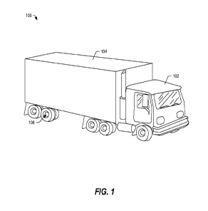
[0011] FIG. 1 depicts a perspective view of a vehicle including a plurality of
wheel
modules with integrated active suspension features, in accordance with certain
embodiments of the present disclosure.
[0012] FIG. 2 depicts a block diagram of a system configured to provide
dynamic active
suspension features, in accordance with certain embodiments of the present
disclosure.
[0013] FIG. 3 depicts an exploded perspective view of structural components
configured
to provide an integrated active suspension, in accordance with certain
embodiments of
the present disclosure.
[0014] FIG. 4 depicts a perspective view of an apparatus including coil having
adjustable
compression, in accordance with certain embodiments of the present disclosure.
[0015] FIG. 5A-5C depict views of a linear actuator portion of the apparatus
of FIG. 4, in
accordance with certain embodiments of the present disclosure.
[0016] FIG. 5D depicts a perspective view of a drive element portion of the
apparatus of
FIG. 4, in accordance with certain embodiments of the present disclosure.
[0017] FIGs. 6A and 6B depict views of the drive element portion of the
apparatus of
FIGs. 4 and 5D, in accordance with certain embodiments of the present
disclosure.
[0018] FIG. 7A depicts a side view of the apparatus of FIG. 4, in accordance
with certain
embodiments of the present disclosure.
[0019] FIG. 7B depicts a side cross-sectional view of the apparatus of FIG.
7A.
CA 03062419 2019-11-04
WO 2018/126241
PCT/US2017/069161
-4-
[0020] FIG. 8 depicts a front perspective view of a portion of a vehicle
including wheel
modules configured to provide independent, integrated active suspension, in
accordance
with certain embodiments of the present disclosure.
[0021] FIG. 9 depicts a method of adjusting compression of a vehicle's
suspension, in
accordance with certain embodiments of the present disclosure.
[0022] FIG. 10 depicts a method of adjusting compression of a vehicle's
suspension to
raise a wheel above the road surface, in accordance with certain embodiments
of the
present disclosure.
[0023] In the following discussion, the same reference numbers are used in the
various
embodiments to indicate the same or similar elements.
DETAILED DESCRIPTION OF ILLUSTRATIVE EMBODIMENTS
[0024] Embodiments of systems, methods, and devices are described below that
can be
configured to provide independent active suspension adjustments, dynamically.
In
general, spring travel or compression travel refers to a measure of a distance
from a
bottom of a suspension stroke (such as when the vehicle is raised on a jack
and the wheel
is hanging freely) to a top of the suspension stroke (when the vehicle's wheel
can no
longer travel in an upward direction). Too much weight or worn springs can
cause the
spring to compress too much, causing the wheel to "bottom out" against an
underside of a
vehicle, which can cause vehicle control problems or damage to the vehicle or
the
wheels. Conventionally, most vehicles utilize passive springs to absorb
impacts and
dampers or shock absorbers to control spring motions.
[0025] Embodiments of systems, methods, and apparatuses are described below
that may
be integrated within a wheel module to provide a dynamically adjustable
compression to
produce an active suspension. The apparatus may include a linear actuator
including an
electromagnetic drive motor configured to drive an extendable piston. The
apparatus
may further include a compressible spring extending over the linear actuator,
and a
rotatable electromagnetic structure configured to engage threads on an
external surface of
CA 03062419 2019-11-04
WO 2018/126241
PCT/US2017/069161
-5-
the electromagnetic motor drive and configured to advance along a length of
the linear
actuator to compress the spring.
[0026] Embodiments of the systems, methods, and apparatuses provide dynamic
adjustment of the suspension of a vehicle for each of a plurality of wheel
modules,
independently. The dynamic adjustments can be used to manage load
distribution,
improve vehicle handling, and enhance ride safety. Moreover, the dynamic
adjustments
can be used to raise a wheel above the ground dynamically, such as when tire
pressure is
low or when the tire is damaged or flat, and to redistribute the load across
multiple other
wheel modules so that the vehicle can continue to travel. Other embodiments
are also
possible.
[0027] Embodiments of systems, methods, and devices may include a mounting
frame
and a pair of adjustable spring devices coupled between the mounting frame and
a frame
of a vehicle. Each of the adjustable spring apparatuses includes a linear
actuator having
an extendable piston, a rotatable or drive element configured to rotationally
advance
along a length of the linear actuator to provide a stop; and a spring
configured to fit over
the linear actuator and to rest on the stop. The rotatable element may be
rotated to move
along threads on an external surface of the linear actuator to apply and
maintain a
compressive force on the spring. The piston of the linear actuator may provide
a second
stop for the spring. The piston may be extended to further adjust the
compression applied
to the spring. By adjusting the position of the rotatable element and the
extension of the
piston of the linear actuator, the suspension stroke may be adjusted and the
compression
on the spring may also be adjusted, providing an active suspension.
[0028] FIG. 1 depicts a perspective view of a vehicle 100 including a
plurality of wheel
modules 106, each of which includes an integrated active suspension, in
accordance with
certain embodiments of the present disclosure. The vehicle 100 may include a
cab 102
and a trailer 104 including a plurality of wheel modules 106. Each wheel
module 106
may include one or more tires and a driven active suspension or coil assembly.
Each
integrated wheel module 106 may include a driven active suspension (coil
assembly)
including a coil and a linear dampening motor configured to define a first
stop for the coil
CA 03062419 2019-11-04
WO 2018/126241
PCT/US2017/069161
-6-
(or spring) and including a rotational motor configured to define a second
stop for the
coil to provide a desired compression.
[0029] In some embodiments, a control circuit may be configured to provide
control
signals to the driven active suspension to control a linear motor of a coil
assembly to
selectively adjust a spring rate and dampening effect of the coils. In some
examples, the
linear motor of the coil assembly may be used to dynamically compress the coil
in a
positive or negative direction. Further, in some examples, the linear motor of
the coil
assembly may dynamically adjust a load on a coil by adjusting a linear motor
relative to
the coil to enhance the operation of the shock absorption, to balance a load,
to assist in
off-setting centrifugal forces during a turn, for other reasons, or any
combination thereof.
In certain embodiments, by adjusting the linear motor, the integrated wheel
module 106
may be raised or lowered relative to the frame of the vehicle.
[0030] FIG. 2 depicts a block diagram of a system 200 configured to provide an
active
suspension, in accordance with certain embodiments of the present disclosure.
The
system 200 may include a control system 202 coupled to a plurality of sensors
associated
with each of the wheel modules 106. The sensors may include spring sensors
204, tire
pressure sensors 206, load sensors 208, steering sensors 210, and road surface
sensors
212. Each sensor 204, 206, 208, 210, and 212 may provide a signal proportional
to a
sensed parameter to the control system 202.
[0031] The control system 202 may include one or more input/output (I/O)
interfaces
214. The I/O interfaces 214 may be coupled to or otherwise configured to
receive signals
from the sensors 204, 206, 208, 210, and 212. The I/O interfaces 214 may be
coupled to
a processor 216, which may be coupled to power storage 220 (such as a
plurality of
batteries) via a power storage I/O interface 218. The processor 216 may also
be coupled
to a memory 222, which may be configured to store processor-executable
instructions as
well as data.
[0032] The memory 222 may include a graphical user interface (GUI) module 224
that,
when executed, can cause the processor 216 to provide a graphical interface
through
which a user may interact with the control system 202. In some embodiments,
the 110
CA 03062419 2019-11-04
WO 2018/126241
PCT/US2017/069161
-7-
interfaces 214 may be coupled to a touchscreen interface or other input device
to view
and configure the active suspension settings of the system 200.
[0033] The memory 222 may also include a tire pressure module 226 that, when
executed, may cause the processor 216 to determine the tire pressure
associated with the
one or more tires of the wheel module 106. The memory 222 may further include
a load
management module 228 that, when executed, may cause the processor 216 to
determine
loads borne by each of the wheel modules 106 and to determine load balancing
adjustments for the active suspension components based on the distribution of
the loads
across multiple wheel modules 106.
[0034] The memory 222 may further include an active suspension module 230
that, when
executed, may cause the processor 216 to determine active suspension
adjustments for
each of the plurality of wheel modules 106. The memory 222 further includes a
rotary
actuator control module 232 that, when executed, may cause the processor 216
to
determine a rotary actuator adjustment based on the active suspension
adjustments. The
memory 222 may also include a spring compression control module 234 that, when
executed, may cause the processor 216 to determine compression on the spring
or coil
based on sensor data from the spring sensors 204. The memory 222 may also
include a
linear actuator control module 236 that, when executed, may cause the
processor 216 to
control the linear actuator of the active suspension.
[0035] The memory 222 can also include an active suspension control module 238
that,
when executed, may cause the processor 216 to send control signals to a rotary
actuator
242 of the wheel module 106 and to a linear motor 244 of the wheel module 106
based on
information determined from the active suspension calculator 230, the rotary
actuator
control module 232, the spring compression control module 234, and the linear
actuator
control module 236.
[0036] The memory 222 may further include other modules 240 that can be
executed by
the processor 216 to perform a plurality of other functions. The other modules
240 may
cause the processor 216 to control operation of the vehicle, to control
operation of one or
more actuators (such as gate lift actuators, compression actuators, and the
like). Further,
CA 03062419 2019-11-04
WO 2018/126241
PCT/US2017/069161
-8-
in the context of an electrical vehicle, the other modules 240 may include
battery status
modules, active suspension control modules, motor control modules, other
modules, or
any combination thereof
[0037] In a particular example, the control system 202 may monitor the balance
of a load
in the trailer 104 as applied to each of the wheel modules 106 and may
selectively adjust
the active suspension of one or more of the wheel modules 106 to balance the
load. In
some embodiments, the control system 202 may determine a suitable damping
parameter
and may adjust the compression applied to the coil to achieve the selected
damping.
Further, the control system 202 may determine a compression stroke based on a
load.
The compression stroke may be adjusted by extending the piston of the linear
motor 244
and by adjusting the stop position of the rotary actuator 242 to provide a
selected
compression. Other embodiments are also possible.
[0038] FIG. 3 depicts an exploded perspective view of structural components
300
configured to provide an active suspension, in accordance with certain
embodiments of
the present disclosure. The structural components 300 may include an upper
mounting
frame 302 and a lower mounting frame 304. The upper mounting frame 302
includes
frame attachment elements 306A and 306B, which may be cylindrical structures
sized to
receive fasteners (such as a bolts) to couple the frame attachment elements
306A and
306B to corresponding features on the frame of the vehicle. The upper mounting
frame
302 further includes slider attachment elements 308A and 308B, which may be
cylindrical structures sized to receive a fastener (such as a bolt) to couple
to a slider 312.
[0039] The lower mounting frame 304 includes frame attachment elements 314A
and a
corresponding element that is obscured from view by the upper mounting frame
302.
The frame attachment element 314A and its corresponding element on the
obscured edge
of the lower mounting frame 304 may include cylindrical structures sized to
receive
fasteners (such as bolts) to couple the frame attachment elements 314 to the
frame of the
vehicle. The lower mounting frame 304 further includes camber housing
attachment
elements 316A and 316B, which may be cylindrical structures sized to receive a
fastener
CA 03062419 2019-11-04
WO 2018/126241
PCT/US2017/069161
-9-
(such as a bolt) to couple the camber housing attachment elements 316A and
316B to a
corresponding receptacle 318 of a camber housing 320.
[0040] The camber housing 320 may include a guide element 322 including a
central
groove 324 forming tracks along an upper surface of the camber housing 320.
The guide
element 322 may be sized to receive a corresponding recess 326 of the slider
312. The
recess 326 includes side walls spaced apart to fit over the guide element 322
of the
camber housing 320. The recess 326 may include a ridge or extension 328 within
the
recess 326 to engage the central groove 324. The slider 312 may be configured
to slide
back and forth along the guide element 322 as indicated by the phantom arrow
327.
[0041] The camber housing 320 may define an enclosure 340 sized to receive a
portion
of an actuator 342, which may include a worm drive having a rotatable gear 344
configured to engage corresponding threads of an articulating shaft 346
configured to
move the slider 312 along the guide element 322. The actuator 342 may be an
embodiment of the actuator 242 in FIG. 2. The camber housing 320 may further
include
a coupling 321 configured to receive a king pin or other fastener to secure a
steering
knuckle or other structure to the camber housing 320. In some embodiments, a
wheel
including a rim and a tire may be coupled to the steering knuckle. In a
particular
example, the actuator 324 may be controlled to adjust the position of the
slider 312
relative to the housing 320 to adjust the camber angle of the wheel.
[0042] The structural components 300 may further include suspension spring
assemblies
348A and 348B. The suspension spring assembly 348A may be coupled at a
proximal
end to a spring attachment element 350A of the lower mounting structure 304
via a
fastener, such as a bolt. The distal end of the suspension spring assembly
348A may
include a frame attachment element 352A configured to couple to a
corresponding
attachment feature of the frame of the vehicle. Similarly, the suspension
spring assembly
348B may be coupled between a spring attachment element 350B (which is
obscured by
the upper mounting frame 302) and a frame attachment element 352B, which may
be
coupled to the frame of the vehicle.
CA 03062419 2019-11-04
WO 2018/126241
PCT/US2017/069161
-10-
[0043] In the illustrated example, the suspension spring assembly 348 may
include a
linear actuator 354 with a piston that includes the frame attachment element
352. The
linear actuator 354 of the suspension spring assembly 348 may include an
attachment
feature at the proximal end for coupling to the spring attachment element
350A. Further,
the linear actuator 354 of the suspension spring assembly 348 may include a
drive
element 356, which may be configured to advance along the length of the linear
actuator
354 by rotating about its external (threaded) surface. The drive element 356
may be
coupled to or may include a coil stop, which may cooperate with a coil stop of
the piston
to apply a selected compression to the coil
[0044] It should be understood that the structural components 300 may be
included with
each of the wheel modules of the vehicle, making it possible to dynamically
adjust the
active suspension of each wheel module independent from every other wheel
module
106. Thus, each wheel can have an independently adjustable active suspension
to
maintain a desired compression stroke and damping based on the conditions.
Further, it
should be appreciated that the active suspension adjustments may be
implemented
dynamically as the vehicle is in motion.
[0045] FIG. 4 depicts a perspective view of an apparatus 400 including an
active
suspension assembly 348 having adjustable compression, in accordance with
certain
embodiments of the present disclosure. The active suspension assembly 348 may
include
the linear actuator 354 with an extendable piston 408, which may extend or
retract in a
direction indicated by arrow 410. The linear actuator 354 may include an
attachment
feature 450 configured to couple to a spring attachment element 350 of a lower
mounting
frame 304. Further, the extendable piston 408 may include the frame attachment
element
352 and a coil stop 412.
[0046] The active suspension assembly 348 may further include the drive
element 356
configured to engage threads on an exterior surface of the linear actuator
354. The drive
element 356 may be configured to rotate about the exterior surface of the
linear actuator
354 as indicated by the arrow 406 to advance along a longitudinal axis of the
linear
CA 03062419 2019-11-04
WO 2018/126241
PCT/US2017/069161
-11-
actuator 354 as indicated by the arrow 404. In some embodiments, the drive
element 356
may be coupled to or may include a coil stop 402.
[0047] In some embodiments, the coil stop 412 and the coil stop 402 may
cooperate to
apply compression to the spring or coil 409. In an example, extension or
retraction of the
plunger or piston 408 and rotation of the drive element 356 may cooperate to
adjust the
compression applied to the spring or coil 409. Other embodiments are also
possible.
[0048] It should be appreciated that significant additional advantages can be
achieved by
combining an active camber adjustment with the active suspension. In an
example,
during cornering, when a load shifts, when the wind is impacting the vehicle
path, and so
on, the active suspension can be configured to lower one or more wheel modules
and to
raise one or more wheel modules dynamically and continuously to counteract the
changing conditions. Such changes may impact the road contact patch of each
tire, and
an active camber adjustment may be continuously and dynamically applied in
conjunction with the changing suspension in order to maintain a desired
contact patch
between each tire and the road surface. An example of such a dynamic camber
system is
described in a co-pending U.S. Application No. __ / filed on December 30,
2017 and entitled "Active Camber Adjustment". Similarly, incorporation of
motor
components, active steering, power storage, and other features into the
integrated wheel
module may achieve further advantages.
[0049] In one embodiment, by adjusting the position of the drive element 356
relative to
the linear motor 354, the spring compression can be adjusted to find a
"neutral point" for
any given load and for each wheel module, independently, so that the
electromagnetic
spring that is in parallel with the coil 409 does not have to expend energy to
hold the load
continuously. Further, the piston 408 and the linear actuator 354 cooperate to
provide an
electromagnetic actuator that can act as a virtual spring in parallel with the
coil 409 and
with a spring rate and damping that is determined by software and configured
by the
control system 202 in FIG. 2.
[0050] In some implementations, the electromagnetic actuator can actively
mitigate
variations in road surface (bumps, potholes, etc., detected from signals of
various sensors
CA 03062419 2019-11-04
WO 2018/126241
PCT/US2017/069161
-12-
within the wheel module or in other wheel modules of the system) in the
context of active
suspension. In an example, when a wheel module encounters a variation in the
road
surface, the active suspension of a next wheel module in the direction of
travel may
adjust the height of the tire, the spring compression, or both in order to
reduce the effect
of the variation in the road surface. In a particular example, a first wheel
module may hit
a bump and each subsequent wheel module may skip or step over the bump,
reducing
vibrations overall and improving the safety of the vehicle.
[0051] In the context of the vehicle, the vehicle attitude can be managed for
conditions
like turns, tilt of the road surface, yaw and pitch of the vehicle, and the
control system of
the vehicle (or the power electronics of each individual wheel module) can
control the
active suspension by anticipating adjustments to be made based on signals from
yaw rate
sensors compared to the steering input. For example, the active suspension may
lower
the wheel modules on one side and raise wheel modules on the other side of a
vehicle to
lean the vehicle into a turn. If each wheel module also includes an active
camber
adjustment feature, the wheel module may also adjust the camber angle of the
tires
independently to maintain a consistent contact patch with the road surface
during the
turning operation. The active camber system and the active suspension system
may
continuously and dynamically adjust the camber angle and the suspension
parameters,
respectively, returning the wheel modules to a previous state when the
operation is
completed.
[0052] It should be appreciated that, to fully utilize these capabilities and
to maximize
grip, vehicle dynamics, performance, safety and efficiency, a vehicle may
utilize the
active camber adjustment as well as the steerable, driven (and rapid
electronic braking of
an integrated wheel module that includes the motor and associated control
electronics. In
combination, these features alter the fundamental characteristics of heavy
vehicles on the
roads.
[0053] The active suspension described herein also allows for additional
features for tire
maintenance, long-haul travel, and so on. In one example, the active
suspension can be
used to raise the tire off the ground to allow for tire changes without a
jack. In another
CA 03062419 2019-11-04
WO 2018/126241
PCT/US2017/069161
-13-
example, the active suspension can independently and selectively raise and
lower wheel
modules for load leveling on tilted roads or to align with loading docks. The
active
suspension can operate to change vehicle ground clearance, to step over large
obstacles
during travel without excessive tipping of the vehicle, which might otherwise
cause the
vehicle to tip over. In another embodiment, in response to a flat tire, the
active
suspension may raise the flat tire off of the road, dynamically adjust the
suspension
parameters of others of the plurality of wheel modules, and allow the operator
to continue
traveling. Other advantages are also possible.
[0054] FIGs. 5A-5C depict views of a linear actuator portion of the apparatus
of FIG. 4,
in accordance with certain embodiments of the present disclosure. In FIG. 5A,
the linear
actuator 354 includes a stator with a plurality of threads 502 on an exterior
surface to
engage corresponding teeth or threads on an interior surface of a drive
element 356.
[0055] FIG. 5B depicts a cross-sectional view 510 of the integrated linear
damping
stator (the linear actuator 354) taken along line B-B in FIG. 5A. The stator
354 can
include a housing including an exterior surface having threads 502 configured
to engage
corresponding threads of the drive element 356. Further, the stator 354 can
include an
insulative layer 514 between the exterior surface including the threads 502
and a plurality
of electrical coils 512.
[0056] FIG. 5C depicts a cross-sectional view 520 of a portion of the
integrated linear
damping stator 354 taken along line C-C in FIG. 5B. The stator coils 512 may
be
separated or segmented by an air gap 522. It should be appreciated that the
implementation depicted in FIGs. 5A-5C represents one possible example of a
housing
for the stator 354. Other embodiments are also possible.
[0057] FIG. 5D depicts a perspective view 530 of a drive element 356 of the
apparatus of
FIG. 4, in accordance with certain embodiments of the present disclosure. The
drive
element 356 may include a central opening sized to fit over the linear
actuator or stator
354 and including threads 532 configured to mate with threads 502 on an
exterior surface
of the linear actuator or stator 354.
CA 03062419 2019-11-04
WO 2018/126241
PCT/US2017/069161
-14-
[0058] It should be appreciated that the drive element 356 can be moved along
the
threads 502 of the linear actuator or stator 354 to achieve a desired
compression of the
coil 409. Once the compression is achieved, the linear actuator or stator 354
may be
turned off and the load may be maintained by the coil 409, allowing for
passive load
handling, such as when the vehicle is parked. Other embodiments are also
possible.
[0059] FIGs. 6A and 6B depict views of the drive element portion of the
apparatus of
FIGs. 4 and 5D, in accordance with certain embodiments of the present
disclosure. FIG.
6A depicts atop view 600 of a drive element 356 of an active coil assembly, in
accordance with certain embodiments of the present disclosure. The drive
element 356
includes a circumferential ring of rare earth magnets 602, which may respond
to an
electrical field in the coils of the linear actuator or stator 354 in FIG. 5A.
Further, the
drive element 356 includes threads 532 configured to mate with corresponding
threads
502 (FIGs. 5A-5C) on an exterior surface of the linear actuator or stator 354.
[0060] FIG. 6B depicts a cross-sectional view of the drive element 356
taken along
line B-B in FIG. 6A, in accordance with certain embodiments of the present
disclosure.
In this example, the threads 532 on an interior surface of the drive element
356 may be
configured to engage corresponding threads of the linear actuator or stator
354. The
threads 532 may include a 12 pitch thread. Other thread configurations are
also possible.
[0061] FIG. 7A depicts a side view 700 of the active coil assembly 348 of FIG.
4, in
accordance with certain embodiments of the present disclosure. The linear
actuator or
stator 354 may be configured to drive the piston 408 to extend or retract.
Further, the
linear actuator or stator 354 may cause the drive element 356 to advance by
rotating and
advancing along the threads 502). By selectively controlling one or both of
the piston
408 and the drive element 356, the compression on the spring 409 can be
adjusted.
[0062] FIG. 7B depicts a side cross-sectional view 710 of the apparatus of
FIG. 7A. The
linear actuator 354 includes a plurality of electric coils 512, which may
interact with
permanent magnets 712 within the piston 408 to extend or retract the piston
408. Further,
the linear actuator 354 may induce electrical fields that can interact with
the permanent
magnets of the drive element 356 to turn the drive element 356, advancing the
coil stop
CA 03062419 2019-11-04
WO 2018/126241
PCT/US2017/069161
-15-
402 to a selected position along the length of the linear actuator 354 as
indicated by arrow
404.
[0063] In operation, the plunger or piston 408 may be extended and the drive
element
356 lowered to reduce the compression on the spring or coil 409 and increasing
the stroke
of the compression. The plunger or piston 408 may be retracted, the drive
element 356
may be raised, or both, to increase the compression on the coil or spring 409.
In each
instance, the linear actuator or stator 354 may be responsive to control
signals from a
circuit to provide an active suspension. Other embodiments are also possible.
[0064] FIG. 8 depicts a front perspective view of a portion of a vehicle 800
including
wheel modules 106 configured to provide independent, integrated active
suspension, in
accordance with certain embodiments of the present disclosure. The vehicle 800
may
include a frame 802 coupled to wheel modules 106A and 106B, each of which
includes
the structural components 300 of FIG. 3, a respective tire 806A and 806B, and
a steering
knuckle 808 connected to the coupling 321 of FIG. 3.
[0065] In the illustrated example, by controlling the actuator 342, the
rotatable gear 344
may be configured to engage corresponding threads of the articulating shaft
346 to move
the camber housing 320 relative to the tire 406 and the frame 402. The slider
312 may
move along the guide 322 (shown in FIG. 3) while the receptacle 318 of the
camber
housing 320 remains rigidly coupled to the lower mounting frame 304A. The bolt
extending through the receptacle 318 and the camber housing attachment
elements 316 of
the lower mounting frame 304 provides a pivot point about which the camber
housing
320 may rotate, allowing the tire 410 to tilt to adjust the camber angle of
the tire 406.
[0066] Further, the active suspension assembly 348 may be coupled between the
lower
frame 304 and the frame 802 of the vehicle 800. As discussed above, the active
suspension assembly 348 may include a linear actuator or stator 354 with an
extendable
piston or plunger 408 (shown in FIGs. 4, 7A and 7B. Further, the active
suspension
assembly 348 includes the drive element 356 and the coil stop 402 configured
to advance
toward the frame 802 to compress the spring or coil 409 and to move away from
the
frame 802 to reduce the compression on the spring or coil 409.
CA 03062419 2019-11-04
WO 2018/126241
PCT/US2017/069161
-16-
[0067] In some embodiments, a control system or control circuit (such as the
system 200
in FIG. 2) may be housed within an enclosed portion of the frame 802 of the
vehicle 800
and may be coupled to the active suspension assembly 348 and to a plurality of
sensors
(not shown) via wired connections. In some examples, the control circuit or
control
system 200 may determine various parameters of the tire, the road pitch, the
road
conditions, the steering control signals, and the load and may selectively
adjust the active
suspension of the wheel modules 106A and 106B.
[0068] It should be appreciated that the coil compression adjustments provided
by the
active suspension assembly 348 may be configured to be different for each of
the wheel
modules 106. In one possible example, the active suspension assembly 348 may
be
adjusted to raise a tire above the surface of the road. In some embodiments,
the control
system or circuit 200 may selectively control the timing of the coil
compression
adjustment for each wheel module 106. Other embodiments are also possible.
[0069] FIG. 9 depicts a method 900 of adjusting compression of a vehicle's
suspension,
in accordance with certain embodiments of the present disclosure. At 902, the
method
900 may include receiving signals from one or more sensors at a control
circuit. The
sensors may include load sensors, spring sensors, and other sensors.
[0070] At 904, the method 900 can include determining a drive element
adjustment for
each wheel module of a plurality of wheel modules based on the received
signals using a
processor of the control circuit. In some embodiments, the drive element
adjustment for
each wheel module 106 may be determined in order to control a position of the
drive
element along a length of the linear actuator 354. In some embodiments, the
drive
element of one particular wheel module 106 may be adjusted compress or
decompress the
spring or coil. Other embodiments are also possible.
[0071] At 906, the method 900 may include determining a piston adjustment for
each
wheel module of the plurality of wheel modules based on the received signals
using a
processor of the control circuit. The piston adjustment for each wheel module
106 may
be determined to control a distance between the frame supporting element 302
and the
CA 03062419 2019-11-04
WO 2018/126241
PCT/US2017/069161
-17-
frame 802 and to extend a distance between the coil stop 402 and the coil stop
412 to
adjust a compression of the coil 409.
[0072] At 908, the method 900 may include selectively sending a signal to one
or more
of the wheel modules to adjust at least one of the spring compression and the
piston
length based on the drive element adjustment and the piston adjustment. In
some
embodiments, the drive element may be advanced or retracted, the piston may be
advanced or retracted, or both. Other embodiments are also possible.
[0073] FIG. 10 depicts a method 1000 of adjusting compression of a vehicle's
suspension
to raise a wheel above the road surface, in accordance with certain
embodiments of the
present disclosure. At 1002, the method 1000 may include detecting a low
pressure
condition associated with a tire of a wheel module of a vehicle that includes
a plurality of
wheel modules. The low pressure condition may include a flat tire.
[0074] At 1004, the method 1000 may include sending a signal to at least one
of a linear
actuator and a drive element to raise the tire to an elevation above the road
surface, in
response to detecting the low pressure condition. At 1006, the method 1000 can
include
selectively sending signals to one or more of the other wheel modules to
adjust at least
one of a linear actuator and a drive element to adjust a suspension parameter
of the
vehicle.
[0075] It should be understood that the flow diagrams of FIGs. 1-10 are
provided for
illustrative purposes only. Steps may be omitted or combined without departing
from the
scope of the present disclosure. Further, it should be appreciated that a
first active
suspension adjustment of a first wheel module and a second active suspension
adjustment
of a second wheel module may be different. Additionally, the first active
suspension
adjustment may be applied at a first time, and the second active suspension
adjustment
may be applied at a second time. Other embodiments are also possible.
[0076] In conjunction with the systems, methods, and devices described above
with
respect to FIGs. 1-10, an apparatus may include an active suspension including
a linear
actuator with a piston defining a first coil stop, a drive element defining a
second stop,
and a coil configured to be compressed between the first and second stops. In
a particular
CA 03062419 2019-11-04
WO 2018/126241
PCT/US2017/069161
-18-
example, the linear actuator may include a stator configured to engage
permanent
magnets of the piston to drive the piston toward or away from the frame of the
vehicle.
Further, the drive element may be configured to rotate about the linear
actuator and to
engage threads of the linear actuator to move along the length of the linear
actuator
housing. Other embodiments are also possible.
[0077] Although the present invention has been described with reference to
preferred
embodiments, workers skilled in the art will recognize that changes may be
made in form
and detail without departing from the scope of the invention.