Note: Descriptions are shown in the official language in which they were submitted.
CA
Blakes Ref.: 78039/00004
WO 2010/087698 PCVNL2010/000014
Method, device and fuel for hydrogen generation
The present invention relates to a method and a device for generating hydrogen
from a fluid
fuel comprising a metal hydride MN, and/or .a metal borohydride M(BH4),,. The
present inven-
tion also relates to a fluid fuel comprising a metal hydride MH, and/or a
metal borohydride
M(BH4)x. Moreover, the invention relates to a (re-) fuelling method for a
hydrogen generation
device.
Several processes are known to generate hydrogen from a fuel containing a
metal hydride or
a metal borohydride.
EP 1 369 947 discloses a hydrogen generating method in which a solution A
comprising 5-
50 % NaBH4, 5-40 % NaOH and the balance water is mixed with a solution B
comprising
51 - 100 % water, and 49-0 % of a water soluble water additive. Solution B has
a pH pref-
erably in the range of 2 to 7. After mixing solution A and B, the molar ratio
NaBH4 : H20 pref-
erably is larger than 1: 5, or, even more preferred, larger than 1: 6.
Solution A and B are
preferably separately metered to a reaction chamber where they are mixed and
react The
decomposition reaction of borohydride is
NaBH4 +4 H20 ->4 H2 + NaOH + B(OHh
In this example, solution A is stabNized due to its alkali (NaOH), and the
reaction is started by
decreasing the pH of the resulting aqueous mixture when adding solution B.
The U.S. Department of Energy (DoE) defined technical targets for hydrogen
delivery and
storage. By 2010, the gravimetric energy capacity should be 1.8 kWh/kg. By
2015 the gra-
vimetric energy capacity should be 3 kWh/kg = 10.8 MJ/kg. The latter value
corresponds to
9.0 wt.-% of hydrogen. The operating ambient temperature should be in the
range of -40 C
to 60 C.
In an 'attempt to meet the 2010 targets, from FY 2006 Annual Progress Report,
p. 377 if.,
tests on a magnesium hydride (MgH2) slurry made within a DoE project are
reported. The
CA 3062505 2 0 1 9 -1 1 -25
CA
Bakes Ref.: 78039/00004
WO 2010/087698 PCT/NL2010/000014
2
tested slurry is a dispersion of MgH2 particles having a size of 100 microns
down to 1 micron
in oils with a 70 % MgH2 load in the dispersion. The slurry provides a fresh
material capacity
of 3.6 kWh/kg. The oils of the slurry protect the MgH2 from inadvertent
contact with moisture
in the air, and the MgH2 reacts very slowly at room temperature, so it is
relatively safe to
handle and can be handled in the air. By adding water to the slurry and mixing
it with the
slurry the reaction is started. The decomposition reaction of MgH2 is:
MgH2 +2 H20 ->2 H2 + Mg(OH)2
In the methods according to the prior art it appears not to be possible to
induce an instanta-
neous reaction at which immediately after the start of the reaction hydrogen
is generated in
sufficient amounts for operating e.g. the hydrogen fuel cell of an automobile.
Therefore, a first object of the invention is to provide a method and a device
for the genera-
tion of hydrogen with which an instantaneous release of hydrogen in
considerable amounts is
possible. It is a further object of the present invention to provide a fuel
being suitable to be
used for hydrogen production with a method and/or device according to the
invention. An-
other object is to provide an easy method for refuelling a hydrogen generating
device, in par-
ticular of refuelling a hydrogen generating device according to the invention.
These and other objects are solved with a method and a device for generating
hydrogen,
according to the invention, wherein the method comprises the steps of:
providing a hydrogen carrier fluid comprising hydrogen carrier molecules or
particles being
dissolved or dispersed in an inert fluid medium, providing an activator fluid,
injecting the hy-
drogen carrier fluid and the activator fluid into a first reaction chamber,
wherein the hydrogen
carrier fluid and the activator fluid are injected into the reaction chamber
in order to cause an
intensive mixing of the hydrogen carrier molecules or particles with the
activator fluid.
According to the method of the invention, a solution or a liquid dispersion is
used as a fuel,
the solution or dispersion comprising hydrogen carrier particles, e.g. micro
particles of a
metal hydride or a metal borohydride, which are dissolved or dispersed in an
inert fluid disso-
lution or dispersion medium. The fuel and the activator fluid are injected
into a reaction
chamber, the injection of the solution or dispersion and the activator fluid
causing an inten-
sive mixing of the fuel with the activator fluid, causing an intimate contact
between the hy-
drogen carrier molecules and the activator fluid. The injection of a
dispersion also causes the
hydrogen carrier particles to be separated from the dispersion medium and to
be exposed to
CA 3 0 62505 2 0 1 9 -1 1 -25
CA
Blakes Ref.: 78039/00004
WO 2010/087698 PCT/NL2010/000014
3
the activator fluid. The injection of the fuel and the activator fluid is
highly preferred to be an
inline injection of both the fuel and the activator fluid.
With this method it is possible to obtain a large contact area between the
surface of the hy-
drogen carrier droplets or particles and the activator fluid, and any
hindrance to the reaction
due to dissolution medium shielding the hydrogen carrier or dispersion medium
adhering to
the surface of the particles is minimized or even totally prevented since the
dissolution me-
dium will be divided into tiny droplets in the activator fluid and the
dispersion medium will be
washed away from the surface of the hydrogen carrier particles. Thus, after
having injected
both the solution or dispersion and the activator fluid into the reaction
chamber, the surface
of the tiny droplets or particles is exposed to the activator and the hydrogen
generating reac-
tion will start immediately and will release hydrogen at a high reaction rate.
In many cases the method will be even more efficient, when the solution or
dispersion and
the activator fluid are injected under high pressure, the suitable pressure,
however, depend-
ing on the solution or dispersion, in particular the droplet or particle size
of the hydrogen car-
rier, the carrier load in the solution or dispersion, the viscosity of the
solution or dispersion,
and the type of activator fluid used. By using high pressure for the injection
of the solution or
dispersion, the injection rate of the dissolution or dispersion fluid and/or
the activator fluid is
increased, thereby increasing the efficiency of dividing the dissolution
medium into tiny drop-
lets or separating the dispersion medium from the surface of the hydrogen
carrier particles.
Moreover, the division of the dissolution medium into tiny droplets or the
separation of the
dispersion medium from the hydrogen carrier particle may be promoted by adding
an emulsi-
tier to the dissolution or dispersion medium and/or the activator fluid, since
it eases emulsifi-
cation of the dissolution medium and washing away the dispersion medium from
the particle
surface.
With the above measures the reaction can start in less than a second after the
injection of
the solution or dispersion and the activator fluid into the reaction chamber.
In a preferred embodiment, the mixture of any remaining hydrogen carrier
particles, disper-
sion medium, activator fluid and reaction products is additionally mixed in a
second mixing
stage. In that stage, the reaction between the remaining hydrogen carrying
particles and the
activator may be completed up to 99% or more, so that basically all the
hydrogen carrier par-
ticles are reacted and the reaction products remain dispersed in the
dispersion medium such
CA 3062505 20 1 9 -1 1 -25
CA
Blakes Ref.: 78039/00004
WO 2010/087698 PCT/NL2010/000014
4
that they can easily be removed from the container where they are stored. In
this context, it
can be advantageous to intermittently or continuously add additional activator
fluid to the
mixture. This second mixing stage may be preferably performed in a high shear
mixer having
a stator and a rotor.
It can be advantageous to employ separating means to separate hydrogen from
the reaction
residues,. in particular a membrane, in order to release all of the generated
hydrogen. Such
separating means are in particular useful at and after the second mixing
stage.
It is further preferred that the total amount of activator fluid slightly
exceeds the stoichiomebic
amount for the reaction with the amount of hydrogen carrier.
A suitable hydrogen carrier is one or more selected from the group consisting
of metal hy-
drides MH, and metal borohydrides M(BH4)., where M is a metal and x denotes
the valence
of the particular metal. Preferably, the metal of the hydrogen carrier is
selected from the
group consisting of Li, Na, Be, Mg, Ca and Al, and the hydrogen carrier in
particular preferred
is Ca(BH4)2 and/or Al(BH4)3.
In order to provide a large surface area for reaction, particle sizes of the
hydrogen carrier of
10 microns or smaller, preferably of about 1 micron or smaller are considered
to be advanta-
geous. Completely dissolved hydrogen carriers are considered to be
particularly advanta-
geous.
As inert dissolution or dispersion mediums, fluids or a combination of fluids
selected from the
group consisting of mineral oils, copolymers of ethylene and propylene,
poly(alpha)olefins
and ether alkoxylates are preferred.
The use of a solution or a dispersion having a concentration of the hydrogen
carrier, or hy-
drogen carrier particles in the dispersion, of at least 60% is preferred in
order to secure a
suitable energy capacity. A concentration in the range of 70 to 75 % seems to
give an advan-
tageous balance between energy capacity, the viscosity of the solution or
dispersion and
protection of the hydrogen carrier against unintentional reaction under
ambient conditions.
However, depending on the hydrogen carrier or the particle size of the
hydrogen carrier, also
higher concentrations may be suitable.
The viscosity of the solution or dispersion is critical insofar as an
efficient injection is more
difficult at higher viscosities. The power required for a fuel pump also is
proportional to the
CA 3 0 625 0 5 2 0 1 9 -1 1 -25
CA
Blakes Ref.: 78039/00004
WO 2010/057698 PCIINL2010/00001.4
viscosity of the fuel pumped and the power input to any pump may be used as a
quality con-
trol parameter throughout the entire product chain. Thus, viscosities of from
1 to 50 times
that of water at room temperature, preferably of 1 to 25 times that of water
at room tempera-
ture, more preferably of from 1 to 10 times that of water at room temperature,
even more
5 preferred of
from 1 to 5 times that of water at room temperature, and most preferred of
from
1 to 2 times that of water at room temperature are considered to be
advantageous.
A preferred activator is or comprises mainly water. The reaction rate between
a hydrogen
carrier and water may dramatically increase with the purity of the water. For
some boro-
hydrides it was found out that the reaction rate increases in the following
order of type of vra-
ter used: tap water < demineralised water < demineralised water treated with
reverse osmo-
sis < demineralised water treated with reverse osmosis and subsequently passed
through an
electrostatic filter.
Alcohols, such as methanol, ethanol and propanol may also be used as suitable
activator
fluids.
In particular when using water it is useful to add an anti-freeze agent, in
particular glycol in
order to decrease its freezing point The addition of an anti-freeze agent is
not necessary
when using an alcohol as an activator fluid. Alternatively heating and/or
insulating means
may be provided to prevent water from freezing.
The device of the invention comprises a reaction chamber, at least one fuel
injector for inject-
ing a fuel and an activator fluid into the reaction chamber, and outlets for
hydrogen and for
the reaction residues. The at least one injector of the device of the
invention is adapted to
induce an immediate hydrogen generating reaction in the reaction chamber when
injecting
the fuel and the activator fluid.
The device of the invention preferably comprises
- a fuel pump upstream of the fuel injector, and/or
- a fuel compartment which is in fluid connection with the fuel
injector, and/or
- an activator fluid pump upstream of the activator fluid injector,
and/or
- an activator fluid compartment which is in fluid connection with the
activator fluid in-
jector; and/or
- a second stage mixer, in particular a high shear mixer, and/or
CA 3 0 62 5 0 5 2 0 1 9 -11 -2 5
CA
Blakes Ref.: 78039/00004
WO 2010/087698 PCT/NL2010/000014
6
- a spent fuel pump for the reaction residues downstream of the reaction
chamber,
and/or
- a spent
fuel compartment for the reaction residues downstream of the reaction cham-
ber.
A second stage mixer, when used, is preferably arranged within the reaction
chamber, in
particular at the bottom of the reaction chamber, where the dispersion medium,
the fuel and
the spent fuel as weN as activator fluid gather after having been injected
into the reaction "
chamber. However, a second stage mixer can also be located in a second
reaction chamber
downstream of the first reaction chamber. A second stage mixer is not used
when the fuel is
a solution.
Separating means are preferably provided for separating the hydrogen from the
reaction
residues. Such separating means can e.g. comprise a semi-permeable membrane.
The compartments for the fuel, the activator fluid and the reaction residues
preferably are
separate flexible containers arranged within one fuel container provided with
a hard shell
which ¨ for safety reasons ¨ can be operated at low pressure in order to
avoid, that any fluid
within the compartments escapes the container. As a further safety precaution,
membranes
are preferably provided to separate the flexible containers for fuel,
activator fluid and spent
fuel. As a still further safety measure, each of the flexible containers and
the hard shell con-
tainer is preferably provided with a line for supplying nitrogen as a
blanketing gas and for
venting any excessive pressure arising in any of the containers. This line is
preferably pro-
vided with a control valve and a mechanical safety valve. In addition, the
flexible containers
and/or the hard shell container may be provided with sensing means for sensing
and moni-
toring the pressure in the containers, the output of which is preferably
communicated to a
user interface.
In a preferred embodiment, each of the fluid lines for providing fuel and
activator fluid from
the fuel container and activator container to the reaction chamber is provided
with a bypass
and a control valve in that bypass, allowing the fuel pump to continuously
recirculate fuel
through the bypass to the fuel container and the activator fluid pump to
continuously recircu-
late activator fluid through the bypass to the activator fluid fuel container.
Upon actuation of
the control valves in each bypass, fuel and activator fluid are fed to the
reaction chamber.
CA 3062505 20 1 9 -1 1 -25
CA
Blakes Ref.: 78039/00004
WO 2010/087698 PCT/NL2010/000014
'7
In another preferred embodiment of the invention a hydrogen output regulation
valve is ar-
ranged downstream the hydrogen outlet of the reaction chamber for regulating
the hydrogen
output of hydrogen from the reaction chamber.
For the operation of the device a controller may be provided which is adapted
to control in
particular the output pressure of the hydrogen, the operation of the fuel
pump, the operation
of the activator fluid pump, the actuation of the control valves in fuel and
activator fluid by-
pass, the operation of the pump for reaction residues and/or the liquid level
within the reac-
tion chamber.
In a preferred embodiment, the reaction chamber Is provided with a first heat
exchanger, for
removing a first portion of the heat of reaction between fuel and activator
from the reaction
chamber, and a second heat exchanger, for removing a second portion of the
heat of reac-
tion between fuel and activator from the mixer in the reaction chamber. By
means of a suit-
able heat transfer fluid the heat from the first heat exchanger is provided to
a heat conversion
cycle, such as an Organic Rankine Cycle (ORC) or a Kalina cycle, which is
connected to a
steam turbine and drives a generator for generating electrical energy.
Alternatively the heat
form the first heat exchanger may be used in a thermo-electric device for
direct conversion of
heat into electrical energy, or may be shared between a heat conversion cycle
and a thermo-
electric device.
The heat from the second heat exchanger is used for heating purposes and/or is
dissipated
to the environment. The maximum temperature of the hydrogen from the reaction
chamber
preferably is limited to 40 C in order to prevent damage to downstream
equipment such as
fuel cell membranes.
The device of the invention may be preferably used for combinations of
dispersions contain-
ing hydrogen carrier particles as a fuel and water or alcohol as activator
fluids. However, the
device can also be used for solutions containing metal hydrides or metal
borohydrides as fuel
and an aqueous activator fluid.
The fuel of the invention consists of a solution or dispersion and an
activator fluid, the pre-
ferred composition and physical properties of which have already been
described above.
In the following, the invention is described in detail with reference to the
drawings, wherein:
Fig. 1 is a schematic representation of a fuel system according to the
invention;
CA 3062505 2 0 1 9 -1 1 -25
CA
Blakes Ref.: 78039/00004
WO 2010/087698 PCT/NL2010/000014
8
Fig. 2 shows a cross section of a first embodiment of a reaction chamber for a
fuel
system according to the invention;
Fig. 3 shows a cross section of part of a high shear mixer, to be used in the
reaction
chamber according to the invention;
Fig. 4 is a schematic representation of a second embodiment of a fuel system
ac-
cording to the invention;
Fig. 5 is a schematic representation of a third embodiment of a fuel system
accord-
ing to the invention;
Fig 5A is a schematic representation of the embodiment of fig. 5, comprising
cooling
circuits, and a stack of fuel cells;
Fig. 6 shows a preferred embodiment of a set of injectors for injecting inline
fuel and
activator;
Fig. 6A shows another preferred embodiment of an injection system for
injecting fuel
and activator inline;
Fig. 66 shows a third preferred embodiment of an injection system for
injecting fuel
and activator inline;
Fig. 7 shows an embodiment of a fuel tank, with flexible compartments for
containing
fuel, activator fluid and spent fuel;
Fig. 8 is a schematic representation of the delivery of the fuel to a vehicle;
and
Fig. 9 is a schematic representation of the delivery of the fuel at a service
station;
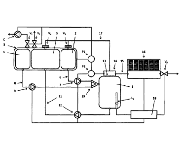
A first embodiment of the fuel system according to the invention is shown in
figure 1. The
system comprises a reaction chamber 1, to which a fuel and an activator fluid
can be sup-
plied. For example, the reaction chamber 1 can be a medium pressure container
allowing
pressures of up to 5 bars.
The fuel to be provided to the reaction chamber is stored in a fuel
compartment 2 of a fuel
tank 3. The fuel tank 3 also comprises an activator fluid compartment 4 for
storing the activa-
tor fluid which is to be provided to the reaction chamber 1, and a compartment
for spent fuel
5 for storing the reaction products (except the generated hydrogen), which are
released from
the reaction chamber 1. All compartments 2, 4, 5 are arranged in a fuel tank
3, the outer pad
of which can be at least partly evacuated via a pressure regulating valve V1
and a compres-
sor C. A preferred pressure within the fuel tank is 150 hPa. The fuel tank 3
can also be
vented via an ambient venting valve V2.
CA 3062505 2 019 -11-25
CA
Blakes Ref.: 78039/00004
WO 2010/087698 PCVNL2010/000014
9
The reaction chamber 1 can be provided with fuel from the fuel compartment 2
via line 6 and
fuel pump 7, and can be provided with activator fluid from the activator fluid
compartment 4
via line 8 and activator fluid pump 9. The reaction residues can be released
form the reaction
chamber 1 via line 11 and pump 12 to be stored in the spent fuel compartment
5. The pumps
preferably are membrane pumps. For the lines and the pumps, preferably
hydrogen tight
membranes and seals are used.
The fuel lines used in the system, preferably comprise tubing having flashback
and flame
arresters and can contain sintered ceramic filters.
Both the fuel and the activator fluid are injected into the reaction chamber 1
through an inline
mixer 19, which may comprise several injection nozzles (not shown). That means
that the
fuel and the activator fluid are injected at the same time and in a way to
ensure a high shear
stress between the surfaces of the fluid jets.
The reaction chamber 1 comprises at least a liquid level sensor Li to monitor
the liquid level
within the reaction chamber. In particular, level sensor 1.4 can monitor and
detect a lower
liquid level, an upper liquid level and an alarm level at adequate levels of
the reaction cham-
ber.
At the top the reaction chamber 1 comprises an outlet for hydrogen which is
separated from
the rest of the reaction chamber 1 by a (hydrogen) gas permeable membrane 13.
Hydrogen
can be released from the reaction chamber 1 through the hydrogen outlet 14 to
either a hy-
drogen buffer (not shown) or a hydrogen consumer (not shown) via line 15, a
pressure regu-
lator 16 and an output regulating valve Vo. The pressure regulator may
comprise mechanical
bellows and shall be hydrogen tight.
Moreover, fitter and check valves V3 and V4, both including hydrogen gas
permeable mem-
branes, are located at the top of the fuel compartment 2 and the spent fuel
compartment 5,
which are connected via line 17 to the hydrogen outlet 14 for the release of
hydrogen from
the fuel compartment 2 and the spent fuel compartment 5.
Two sensors P1, P2 are provided for monitoring the pressure in the fuel tank
and the hydro-
gen gas pressure at the outlet 14 of the reaction chamber 1.
CA 3 0 625 0 5 2 01 9 -11 -25
CA
Blakes Ref.: 78039/00004
WO 2010/087698 PCT/NL2010/000014
The fuel system is controlled by a controller 18. The controller 18 uses the
information from
the pressure sensors PI, P2, the liquid level sensor LI to control either the
pumps 7,9, 12
and the valves VG, Vi, Vs, Vs. In particular, by separately controlling the
pumps 7 and 9 the
mixing ratio of fuel and activator fluid provided to the reaction chamber 1
can be closely con-
5 trolled which enables the close control of the hydrogen generating
reaction in the reaction
chamber 1. A processor arrangement for controlling fuel and activator may have
standard
pre-selected settings for various fuels.
In figure 2, the bottom part of the reaction chamber 1 of the system according
to figure us
10 shown in more detail. A high shear mixer 30 is arranged at the bottom of
the reaction cham-
ber 1, slightly off-centre relative to a central axis 21 and below the liquid
level, which is
schematically indicated with reference number 22.
The object of the high shear mixer 30 is to allow fuel and/or partly spent
fuel to recirculate
over the mixer 30 to provide an additional mixing step and in order to allow
complete conver-
sion of all fuel. This additional mixings step will also prevent the
occurrence of local high
and/or local low concentrations of fuel particles which could create unwanted
hot and cold
spots. Figure 2 shows that the high shear mixer induce a circular flow in the
reaction cham-
ber 1 as indicated by arrow chains. This means that the fluid will flow
upwards along the
shaft of the high shear mixer and thereafter flow downwards along the walls of
the reaction
chamber 1. The fact that the fluids are mixed in this way will help to
increase the shear stress
of the surfaces of the fluids on each other in order to enhance mixing of the
fluids and in or-
der to increase the reaction time of hydrogen production of the system.
Part of a suitable high shear mixer 30 is shown in figure 3. The high shear
mixer 30 corn-
prises a circular stator 31 and concentrically thereto a rotor 32 having a
smaller diameter
than the stator. The rotation axis of the rotor 32 is arranged in order to
allow the rotor 32 to
rotate inside the stator 31 to thereby mix the fluids in the reaction area 33
between the stator
and the rotor. The reaction area 33 is defined by the inner wall of the stator
31 and the facing
outer wall of the rotor 32.
In order to further enhance the release of hydrogen from the fuel, additional
activator fluid
may be provided to the reaction area 33 through openings 34 in the wall of
rotor 32. Spent
fuel may be released from the reaction area 33 through openings 35 in the wall
of the stator
31.
Returning to figure 1, the hydrogen produced in the reaction chamber 1 will be
forwarded to
the pressure regulator 16. In order to secure the purity of the generated
hydrogen this low
CA 3062505 2 019 -11-25
CA
Blakes Ref.: 78039/00004
WO 2010/087698 PC1'/NL2010/000014
11
pressure regulator 16 may require an entry filter. For safety reasons a flame
arrester should
be provided to prevent flash back. The filter and flame arrester may be
combined into one
functional element.
With reference to figures 4 and 5, a second and a third embodiment of a fuel
system accord-
ing to the invention will be described. According to figure 4 the system
comprises a fuel stor-
age compartment 100, an activator storage compartment 200 and a spent fuel
storage com-
partment 300. Each of the compartments 100, 200, 300 is provided with a sensor
721, 722,
723, respectively, for sensing the fluid level inside each of the compartments
100, 200, 300.
These sensors 721, 722, 723 are preferably a Hall sensor or an optical
displacement meas-
uring system. A Hall sensor is magnetic and operates spark free.
Preferably, each of the storage compartments 100, 200, 300 has a flexible
volume. This
means that they are preferably arranged such that a volume increase in one of
the compart-
ments is completely are partly accompanied by a simultaneous volume decrease
of the other
storage compartment. The effect of this measure is an important limitation of
the total amount
of volume needed for the fuel tank comprising the three compartments 100, 200,
300. Be-
fore the system is used the fuel storage compartment 100 and the activator
storage com-
partment 200 will have a certain volume to contain a fluid. At the same moment
the spent
fuel storage compartment 300 will be empty. During use the fuel storage 100
and activator
compartment 200 will be emptied and at the same time the spent fuel
compartment 300 will
be filled up. When using flexible walls, which are able to follow the filling
grade of the com-
partments 100, 200, 300, the initial space needed to accommodate the
compartments 100,
200, 300 can be kept to a minimum. The systems according to figures 4 and 5
can be-used
having flexible storage compartments 100, 200, 300 in a rigid exterior housing
with a fixed
volume. An embodiment of such a tank will be described with reference to
figure 7.
As shown in figure 4, the storage compartments 100, 200, 300 are preferably
connected to a
connector 114. This connector is used to connect the storage compartments to
lines for sup-
plying fluids to and from the storage compartments 100, 200, 300 from one
central location.
The connector 114 is provided with a sub-connector 111 for fuel supply, a sub-
connector 211
for activator supply and a sub-connector 331 in order to release spent fuel
from the system.
The connector is also provided with a sub-connector 344 to supply a blanket
gas, such as
nitrogen to the storage compartments 100, 200, 300. Preferably the sub-
connectors are de-
signed to have unique couplings that prevent the making of any undesired
connection. The
CA 3062505 2 0 1 9 -1 1 -25
CA
Blakes Ref.: 78039/00004
WO 2010/087698 PCT/NL2010/000014
12
sub-connectors preferably are completely free of any spills. A preferred type
of connector
includes the quick connect series of Swagelok.
The fuel storage compartment 100 and activator storage compartment 200 are
provided with
a supply line 110, 210 respectively, for supplying fuel and activator (with or
without a rinsing
fluid) from an external source.
The spent fuel storage compartment 300 is provided with a line 330 for
discharging spent
fuel to an external collection system and the spent fuel discharge line 330 is
provided with a
valve system and a connector 331 for connecting to an external spent fuel
collection system.
Each of the valve systems and connectors 111, 211, 331 may be integrated. The
connectors
and/or the integrated valve system and connectors may be combined in a single
connector
114, which may be operated as one connector, comprising all connections. This
allows for
simultaneous filling of the compartments 100 and 200 and the purging of
compartment 300.
As shown in figure 5, the storage compartments 100 and 200 may be provided
with a recircu-
lation line 120, 220 provided with a pump 125, 225 or, alternatively, with an
impeller 106, 206
(see figure 4) for homogenisation and/or pumping purposes. A screen (not
shown) may be
provided in the upper section of the storage compartments 100, 200, just
downstream of any
recirculation line outlet for even distribution.
An impeller 106, 206, 306 (see figure 4) is preferred for liquids while a
circulation system is
preferred for dispersions. Recirculation of a dispersion allows the fuel to be
evenly distributed
over the total storage compartment area thus minimizing difference in
concentration, while
circulating liquids may result in concentration gradients. Since the activator
will always be a
fluid and not a dispersion, an impeller 206 is preferred for the activator
fluid compartment
200.
The outlet of the recirculation line 120, 220 is provided with a maximum
pressure relief valve.
These valves are used to keep the maximum pressure in the fuel recirculation
line typically at
8 bars and the maximum pressure in the activator line at 9 bars.
The fuel 100, the activator 200 and the spent fuel storage compartment 300 are
preferably
provided with a gas ¨ fluid separation membrane at the inlet for nitrogen. The
nitrogen line
340 is provided with a mechanical pressure relief valve 341 for venting any
excessive pres-
sures (>7 bar) to the environment. The nitrogen line 340 is further provided
with a bypass
(not shown) having a pressure transducer which may actuate a control valve.
During refuel-
ling, nitrogen is supplied to the storage compartments 100, 200, 300 at a
pressure of 3 bars.
CA 3062505 2 0 1 9 -1 1 -25
CA
Blakes Ref.: 78039/00004
WO 2010/087698 PCT/NL2010/000014
13
The controller 58 will control the pressure in line 340 by means of a
transducer and a valve at
a level between of 3.0 and 3.2 bars.
The systems according to figures 4 and 5 are provided with a reactor chamber
400, a mixing
chamber 500 and a buffer chamber 600 for released hydrogen. Each of the
reactor chamber
400, the mbdng chamber 500, and the buffer chamber 600 are in open
communication to one
another, allowing the unrestricted release of hydrogen.
The storage compartments for fuel 100 and activator 200 are connected to the
mixing chain-
ber 500 with a line for supplying fuel 130 and a line for supplying activator
230. Each of these
lines 130, 230 is used to provide the reactor chamber 400 with fuel and
activator, using a
control valve 132, 232 that is positioned at the end of the line at the
entrance of the mixing
chamber 500. The control valves 132, 232 have an opening pressure of 8 bars
for fuel and
an opening pressure of 9 bars for activator. Each of the lines 130, 23018
provided with a
pressure transducer 713, 714 and may be provided with a minimum and maximum
pressure
switch. Each of the lines 130, 230 is preferably provided with fluid control
sensors 133,233
and volume flow meters 134, 234. By locating fluid control sensors between the
control
valves for activator and fuel and the mixing chamber 500, the presence of fuel
and activator
in the lines is monitored (or checked) and no fuel can be dosed to the mixing
chamber 500
without the presence of any activator. Thus the reaction of additional
activator (for reducing
the viscosity measured via recirculation) with a very high concentration of
fuel in the reactor
room is prevented and as a result the pressure in the reactor chamber is
prevented from ex-
ceeding way above the alarm limits.
In the embodiment according to figure 4, the line 230 for supply of activator
may be provided
with a buffer 237 for holding a small volume of activator in order to maintain
a constant liquid
pressure in line 230. The line 130 for supply of fuel may be provided with a
buffer 137 for
holding a small volume of fuel in order to maintain a constant liquid pressure
in line 130.
In the embodiment according to figure 5 this buffer function is obtained by
using the by-
passes 120 and 220.
With reference to figure 6 an embodiment of the injectors for injecting fuel
and activator in the
mixing chamber is shown. The outlet of line 230 is preferably shaped as a
nozzle 232 such
that activator released from the line 230 may be injected into the mixing
chamber 500 as a jet
flow, while the outlet of the fuel line 130 is shaped as an open fluid passage
connected to a
dish-shaped element. The nozzle 232 providing the jet flow may be located in
line with the
CA 3062505 2 0 1 9 -1 1 -25
CA
Blakes Ref.: 78039/00004
WO 2010/057698 PCVNL2010/000014
14
open fluid passage of fuel line 130 such that the jet flow wiN automatically
mix with any fuel
released from the open fluid passage. The jet flow is arranged such that an
intensive mixing
between the fuel and the activator is obtained in order that most of the
protecting fluids from
the solid particles of a fuel granulate dispersion are removed.
The mixing of the fluids comprises a first stage 550 where the activator line
nozzle 232
sprays a relatively powerful jet of activator fluid into a flow of fuel which
is released by the
fuel Nne 130 in a first dish-shaped outlet, thereby flushing the oil from the
granulate and ex-
posing the fuel to the activator. The reacting mixture flows through a first
perforated separa-
tion 558 to the second stage 560 where it is guided by guide 569 to a second
dish-shaped
outlet of remixing line 420, where it is mixed with spent fuel which is re-
circulated from the
receiver area 450 to the second stage 560 of the mixing by pump 425 through
bypass 420
(see figure 5).
The reaction mixture from the second stage may flow through a second
perforated separa-
tion 568 to a third stage 570 in order to allow completion of the reaction,
prior to flowing
through a third perforated separation 578 into the reactor 400. Alternatively,
the reaction mix-
ture may flow from the second stage directly into the reactor 400.
With reference to figure 6A, a cross section of the mixing chamber 500 from
figure 5A is
shown in more detail. Figure 6A shows the fuel line 130, the activator line
230, a cooling
jacket 501 which may completely surround the interior channel 502.
Figure 68 shows a cross section of another preferred embodiment of a mixing
chamber 500
in more detail. The interior channel 502 has layered compartments, divided by
cooling ele-
ments 503 provided with cooling channels 504 for carrying a cooling fluid.
Returning to figures 4 and 5, the mixing chamber 500 preferably has multiple
stages which
are in open communication to one another and ultimately communicate with the
reactor
chamber 400 and the buffer chamber 600. By providing a multiple stage mixing
chamber
500, wherein the different stages are separated by perforated plates having a
decreasing
flow resistance, a pressure gradient is created which causes turbulent mixing
in each stage
and which drives the reaction products from one stage to the next and so on.
This means
that the outlet for produced hydrogen (including the safety valve) cannot be
placed inside the
mixing chamber and will be placed in the reactor chamber 400. The number of
stages will
depend on the desired reaction rate.
CA 3062505 2 019 -11-25
CA
Blakes Ref.: 78039/00004
WO 2010/087698 PCI7NL2010/000014
The lower part of the reactor chamber 400 is shaped such that this lower part
will receive
non-gaseous reaction products from the mixing of fuel and activator. The lower
part is here-
inafter referred to as "receiver area" 450. The non-gaseous reaction products
are spent fuel,
5 which is collected in the receiver area 450 by gravity and the gas
pressure in the reactor
room. The convex shape of the receiver area 450 allows easy transport of the
spent fuel from
the reactor chamber 400 to the receiver area 450.
The receiver area 450 is preferably connected to the storage compartment for
spent fuel 300
10 via a first 430 and a second line 440 for transporting spent fuel. The
second line 440 is a
backup for the first in case the first line would be blocked. The back up
prevents that any
electrical and/or mechanical flow problems may cause malfunction. Furthermore,
it prevents
blockage of the discharge valve and/or the line due to sedimentation, which
may be sticky in
case a fuel dispersion is used. Each of the lines 430, 440 is provided with a
discharge valve
15 431, 441 respectively and each of the discharge valves 431, 441 is
positioned in that essen-
tially all of the spent fuel collected in the reactor chamber 400 may be
remixed prior to being
transported to the spent fuel storage compartment 300.
The discharge valve is preferably located at the bottom of the convex shaped
receiver area
450 and the collected spent fuel in the reactor room is preferably re-
circulated at all times in
order to assure that the fuel is used in total and to enable a viscosity
measurement in the
collected spent fuel through a tachometer and a power sensor attached to the
remixing
pump.
The receiver area 450 is preferably connected to the mixing chamber 500
through a bypass
420 (see figure 5) for remixing spent fuel. The bypass 420 is provided with a
pump 425 and a
control valve 421, which is located below the low alarm level in the reactor
room. The bypass
420 for remixing spent fuel connects to a second stage of the mixing chamber
which is close
to the first stage for mixing fuel and activator. The receiver area 450 may
further be provided
with a temperature sensor 717.
The remixing line 420 is preferably provided with a viscosity meter (not
shown) for sensing
the viscosity of the spent fuel. The pump 425 in the bypass 420 is preferably
provided with a
tachometer (not shown), more preferably a Nipkov disk. The power line of the
pump 425 is
preferably provided with a power sensor (not shown).
CA 3062505 2 019 -11-25
CA
Blakes Ref.: 78039/00004
WO 2010/087698 PCVNL2010/000014
16
The control system for the reactor chamber 400 has four fluid control levels:
a minimum and
maximum control level for the collected spent fuel, a low alarm level, which
may be equal to
the minimum level and a high alarm level which wiN always be higher than the
maximum con-
trol level. The high alarm level actuates the backup (second) discharge valve
while the
maximum level actuates the first discharge valve. At minimum control level all
actuated dis-
charge valves will be dosed. At low alarm level however, the spent fuel
remixing pump 425 is
stopped. If the fluid level goes down to the low alarm level (and at the same
reaches the
minimum level) the remixing pump will stop pumping and the discharge valves
are closed.
When the fluid level rises, the remixing pump will immediately be actuated.
Each of the discharge valves 431,441 is located below the minimum level while
the remixing
outlet valve is located below the low alarm level in the receiver area 450.
Discharge valves
431,441 are preferably at the same height as the valve/outlet for the remixing
line, in order
to prevent blockage due to sedimentation. A separate remixing outlet and valve
in the reactor
room is preferred over a combination with discharge valves and lines in order
to reduce criti-
cal malfunction. Other configurations may of course be used to remix (part of)
the collected
spent fuel.
The reactor chamber 400 may be provided with a connector 414 and control valve
411 for
adding standard activator or an alternative activator to clean the system.
Control valve 414
may be connected to the activator supply line 230.
The buffer chamber 600 is provided with a gas release line 630, which is
provided with a
control valve 631 and a pressure reduction valve 632 downstream of the control
valve. Fur-
thennore, the gas release line 630 is preferably provided with a flame
arrester (not shown)
downstream of the reduction valve 632 to prevent the propagation of any flame
into the
buffer chamber. A filter 603 is preferably provided between the buffer chamber
600 and the
pressure reduction valve 632 for separating reaction products and allowing
hydrogen to
pass. A small volume buffer chamber will easily splash liquid to the outlet
and hence to any
system attached to the gas release line 630, due to the relatively small
length to cross, and
therefore requires a fitter. In large industrial applications very large
volume buffers may be
used which do not require filters since the length to cross will be long.
Splashes may how-
ever still occur.
CA 3062505 2 0 1 9 -1 1 -25
CA
Blakes Ref.: 78039/00004
WO 2010/087698 PCTRiL2010/000014
17
The buffer chamber 600 is preferably provided with a mechanical pressure
relief valve 602
for safety reasons. The temperature of the released gas is preferably measured
by a tem-
perature sensor 718.
The reactor chamber 400 is preferably integrated with and also used as the
buffer chamber
600, including all provisions of the reactor chamber. If the buffer chamber
600 is the reactor
chamber 400 then the pressure reduction valve and the filter are preferably
located on top of
the reactor chamber 400. The mixing chamber 500 may also be placed in the mid
section of
the reactor chamber 400. This also goes for the safety relief valve in order
to maximize the
distance between this valve and any spent fuel splashes. Placing a filter
distant from the
pressure reduction valve creates a second buffer chamber which has an open
connection to
the reactor room.
The integrated reactor chamber 400 is provided with a first 711 and a second
712 pressure
transducer. The first pressure transducer 711 is preferably located upstream
of the filter 603
and the second pressure transducer 712 is preferably located between the
filter 603 and the
pressure reduction valve 632. The reactor chamber may further be provided with
a tempera-
ture sensor 716.
The system according to in figures 4 and 5 is preferably provided with a
control system 50 for
controlling the mixing of fuel and activator, the flow of remixed spent fuel
and the discharge
of collected spent fuel, wherein the control of mixing fuel and activator is
independent from
the control of discharging the spent fuel.
The control system 50 is preferably connected to fluid control sensors 133,
233; pressure
transducers 711, 712, 713, 714, 132, 232, 343; temperature sensors 716, 717,
718; a vis-
cosity meter and/or a tachometer and/or a power sensor. The control system
5018 preferably
provided with a user interface/display 51 and an algorithm for controlling all
sensors and ac-
tuators. The controller 50 may be provided with a wireless communication
system for com-
municating the filling status, fuel quality, pressure safety, etc.
The system preferably is arranged such that the electric resistance in the
conducting metal
parts is less than 0.1 ohm and that the potential difference between any
conducting metal is
less than 10 mV.
The heat generated in the mixing chamber 500 by mixing fuel and activator is
preferably re-
moved by a first cooling system (not shown), using water as a cooling medium,
such that in
CA 3062505 2019-11-25
CA
Blakes Ref.: 78039/00004
WO 2010/087698 PCIINL2010/000014
18
the mixing chamber an operating temperature range of 130 ¨ 200 C is
maintained. A second
cooling system not shown may be provided, using water as a cooling medium, to
maintain the
receiver area 450 and the gas outlet 630 at a maximum temperature of 40 C. By
controlling
the temperature of the gas outlet 630, the humidity of the released hydrogen
is controlled.
In practice the system according to figures 4, 5 and 6 would be used as
follows:
the fuel storage tank 100 may be pressurized with nitrogen to prevent moisture
from pene-
trating during refuelling. As a safety precaution an overpressure vent valve
may be provided
which may be integrated with the fuel inlet valve 111.
=
The spent fuel tank 300 may contain a sight hydrogen pressure from post
reaction of the
binary fuel system which has not yet fully reacted. A pressure transducer 342
is provided to
sense the pressure in the spent fuel tank 300 and if the pressure exceeds a
predetermined
value, the controller 50 actuates control valve 343 to release the excessive
pressure to the
environment Any such actuation is displayed on the interactive
interface/display 51.
The fuel and activator are pumped through lines 130, 230. Pressure transducers
132, 232
sense the pressures in the lines in order to monitor and guarantee the working
pressure of
the nozzles through controller 50.
In order to measure the amounts of fuel and activator, mass flow meters 134,
234 are re-
spectively provided in the fuel 130 and activator 230 lines. Based on the
measured flows of
fuel and activator, the controller 50 determines the actual fuel-to-activator
ratio and compares
that value with the initial set value. Optical sensors 133, 233 sense the
presence of fluids at
the valve systems 132, 232 respectively and the signals from these sensors
enable the con-
troller 50 to prevent the uncontrolled release of hydrogen gas due to an
unbalance in the
fuel-to-activator ratio as a result of the unintended release of just fuel or
just activator.
The activator kne 230 is preferably provided with a filter in order to ensure
that the quality of
the water in the activator meets a conductance value < 0.5 JS, such that the
reaction be-
tween fuel and activator may be completed.
The outlets of fuel line 130 and activator line 230 preferably contain check
valves to prevent
leakage of fuel and activator. In this way a constant opening pressure is
realized. The fuel-to-
activator ratio is calculated from measured fuel and activator volumes and the
required open-
ing times of the valves for the fuel and activator are determined. For safety
reasons the acti-
CA 3062505 2 019 -11-25
CA
Blakes Ref.: 78039/00004
WO 2010/087698 PCVNL2010/000014
19
vator check valve is always opened prior to opening the fuel check valve and
is always
closed after dosing the fuel check valve.
In order to make sure that the spent fuel is completely exhausted, it is re-
circulated to the
mixer through line 420 by actuating pump 425. This intermediate process is
controlled be-
tween minimum and maximum liquid level by level switches 724, 725. In
operation a con-
stant pumping rate of the re-circulation pump is maintained by the controller
50 using the
input from a tachometer. By also determining the power absorbed by the pump at
that rate, a
measure for the viscosity of the spent fuel is determined. By using a lean"
fuel-to-activator
ratio, additional activator is required for the complete release of all
hydrogen stored in the
hydride fuel. The amount of additional activator can be controlled by the
controller 50 based
on the viscosity of the spent fuel.
By mixing fuel and activator hydrogen gas is released instantaneously.
Starting and stopping
the simultaneous flow of fuel and activator implies starting and stopping the
release of hy-
drogen gas. This allows the process to be controlled. The amount of hydrogen
gas released
depends on the amount of fuel injected, since completion of the process
requires an excess
of activator to be present in the reactor. The spent fuel control is similarly
adjusted. By actu-
ating valves 132 and 232 in the fuel 130 and activator 230 lines, a pressure
increase of pump
235 in the activator line 230 suffices to increase the amount of activator and
thereby adjust
the fuel-to-activator ratio and adjust the viscosity.
The chemical reaction between fuel and activator is independent of the
pressure generated
in the reaction chamber 400. Up to a pressure of 50 bars this does not affect
the intended
control range. The hydrogen pressure in the reactor is also used to displace
spent fuel from
the reactor 400 to the spent fuel storage tank 300 through discharge lines 430
and/or 440.
Such displacement is controlled by actuating discharge valves 431 and/or 441.
The outlet of the reactor 400 is provided with a gas/fluid filter 603 to
prevent fluids to be re-
leased from the reactor. Since this filter may be blocked, a first pressure
transducer 711 is
provided in the reactor and a second pressure transducer 712 is provided in
the hydrogen
gas line 630. By comparing the recorded pressure curves of first 711 and
second 712 trans-
ducer, the algorithm of the controller 50 may signal any pressure differences
indicating e.g.
blockage of filter 603. Another safety precaution includes a specific
algorithm of the control-
ler, which continuously relates pressure increases to fuel dosage and signals
any unex-
pected pressure increases.
CA 3 0 625 0 5 2 0 1 9 -1 1 -25
CA
Blakes Ref.: 78039/00004
WO 2010/087698 PCT/NL2010/000014
With reference to figure 5A, a mixing chamber 500 is provided in buffer
chamber 600, com-
prising a pressure transducer 715 for sensing the pressure in the mixing
chamber and a
temperature sensor 716 for sensing the temperature in the mixing chamber.
5
A first cooling circuit 510 is connected to the mixing chamber 500, to remove
a first part of
the heat of reaction between fuel and activator for heat receovery purposes.
The first cooling
circuit 510 comprises a first heat exchanger 512, driving a generator 513 for
converting heat
into electrical power. The circuit 510 further comprises a pump 515 for
pumping cooling fluid
10 having a relatively low temperature to the mixing chamber 500.
A second cooling circuit 460 is connected to a cooling spiral 451 which is
provided in the
receiver area 450, to remove a second part of the heat of reaction between
fuel and activa-
tor. The second cooling circuit 460 comprises a second heat exchanger 462,
which may be
15 used for heating purposes or for dissipating the heat removed from the
receiver area to the
environment The circuit 460 further comprises a pump 465 for pumping cooling
fluid having
a relatively low temperature to the cooling spiral 451. The receiver area 450
is also provided
with a mixer 406, in order to mix and homogenize the mixture of fuel and
activator.
20 The gas release line 630 Is provided with a third heat exchanger 633,
in order to control the
temperature of the hydrogen and thus the moisture content of that hydrogen
which is re-
leased from the buffer chamber 600. The third heat exchanger 630 may be
connected to a
separate cooling circuit not shown e.g. an air conditioning circuit of a
vehicle.
The gas release line 630 is connected to a fuel cell stack 650, 651, 652
through control
valves 634, 635, 636, allowing each of the fuel cells 650, 651, 652 to be
operated in their
optimum performance window separately and independently. The fuel cell stack
is further
provided with an ambient air supply line 640 comprising a first filter 641 for
removing any
dust from the air taken in by the supply line, a pump 645 for pumping air, a
second fitter 642
for actively removing any contamination which has passed the first filter 641
and which may
deteriorate the performance of the fuel cells 650, 651, 652 such as sulfides.
The outlet of the
fuel cell stack is connected to a fourth heat exchanger 660 for condensing
water from the
exhaust of the fuel cells 650, 651, 652, having an inlet 661 for receiving the
fuel cell exhaust,
a first outlet 662 for releasing relatively cool and relatively dry air, and a
second outlet 663 for
releasing condensed water which is pumped to the activator line 230 by pump
665. In order
CA 3062505 2 019 -11-25
CA
Blakes Ref.: 78039/00004
WO 2010/087698 PCT/NL2010/000014
21
to prevent any contamination in the condensed water to enter the mixer, the
activator line
230 is provided with a filter 236.
The connector 114 is provided with a wireless connection 115 to the refuelling
dispenser (not
shown) and/or to the controller 50.
For every kg of hydrogen generated, the system according to the Invention
produces some
44 MJ of heat. The majority of this heat is produced in the mixer, resulting
in local tempera-
tures exceeding 200*C, while a smaller portion will end up in the spent fuel
and hydrogen,
with temperatures in the range 40¨ 60 C.
Therefore, the reaction chamber is preferably provided with a first heat
exchanger, for remov-
ing a first portion of the heat of reaction between fuel and activator from
the reaction cham-
ber 1, and a second heat exchanger, for removing a second portion of the heat
of reaction
between fuel and activator from the mixer 30 in the reaction chamber. By means
of a suitable
heat transfer fluid, having an inlet temperature of e.g. 800C and an outlet
temperature of e.g.
2000C, the heat from the first heat exchanger is provided to a heat conversion
cycle, such as
an Organic Rankine Cycle (ORC) or a Kalina cycle, which is connected to a
steam turbine
and drives a generator for generating electrical energy. Alternatively the
heat form the first
heat exchanger may be used in a thermo-electric device for direct conversion
of heat into
electrical energy, or may be shared between a heat conversion cycle and a
thermo-electric
device. Obviously the highest heat transfer will be achieved by providing a
counter-current
flow of heat transfer fluid relative to the flow of fuel.
The maximum temperature of the hydrogen from the reaction chamber preferably
is limited to
40 C in order to prevent damage to downstream equipment such as fuel cell
membranes. By
means of a suitable heat transfer fluid, such as water having an inlet
temperature of e.g.
20oC and an outlet temperature of e.g. 40oC, hydrogen is cooled and
subsequently the
spent fuel is cooled to an outlet temperature of e.g. 60 C. The heat from the
second heat
exchanger is used for heating purposes and/or is dissipated to the
environment.
A Rankine cycle is a thermodynamic process for converting (residual) heat to
work. In prac-
tice , a medium such as water is turned into overheated steam by heating to a
temperature
well beyond the boiling point. The overheated steam is fed to a steam turbine
driving a gen-
erator, where it expands. The expanded steam is subsequently condensed and
pumped to
CA 3 0 625 0 5 2 0 1 9 -1 1 -25
CA
Blakes Ref.: 78039/00004
WO 2010/087698
PCT/NL2010/000014
22
the evaporatcir where the cycle is repeated. The steam is overheated in order
to prevent
condensation in the steam turbine.
When operating the system according to figures 4, 5 and 6 the following
parameters could be
used:
- fuel-to-activator volumetric ratio (default) 100/90
- fuel line bypass opening pressure 8.0 bars
- activator line bypass opening pressure 9.0 bars
- reactor chamber lower pressure control level 4.5 bars
- reactor chamber upper pressure control level 5.0 bars
- reactor chamber lower pressure alarm level 4.0 bars
- reactor chamber upper pressure alarm level 6 bars
- reactor chamber mechanical relief valve action level 8 bars
- reactor chamber upper disabling pressure for activator >5 bars
- reactor chamber upper disabling pressure for fuel >5 bars
- reduction valve pressure 0.5 bar
- fuel and spent fuel storage compartment upper pressure alarm level 4.5
bars
- fuel and spent fuel storage compartment mechanical relief valve action level
7 bars
- reactor chamber upper temperature level 80 C
- nitrogen fill pressure storage compartments 3 bars
- control band nitrogen fill pressure storage compartments 3.0 ¨ 3.2
bars
When operating the system according to figures 4-6 the following steps should
be followed
when the system is started up:
1. On power up, all sensors are checked by the control system 50.
2. The level sensors 721, 722, and 723 indicate the amount of fuel,
activator and spent
fuel in the storage compartments 100, 200, and 300.
3. The pressure transducer 342 measures the actual pressure in the storage
compart-
ments 100 - 300.
4. The pressure transducers 132, 232 sense the actual pressure in the lines
for fuel and
activator 130, 230.
5. The pressure transducers 711, 712 sense the actual pressure in the
reactor chamber.
The upstream and downstream pressures according to pressure transducers 711,
712
are compared (check) and the best value is selected.
CA 3062505 2 019 -11-25
CA
Blakes Ref.: 78039/00004
WO 2010/087698 PCT/NL2010/000914
23
6. If the pressures according to pressure transducers 711, 712 differ more
than e.g. 10%
this is signalled to a user interface/display 51 as an early warning of
blockage of fitter
603.
7. If this apparent pressure difference persists or increases, the filter
603 must be re-
placed.
8. The level sensors 724-725 indicates the amount of spent fuel collected
in the reactor
chamber 400.
9. The optical sensors 133,233 sense the presence of fluid in the fuel 130
and activator
230 lines.
10. If a level sensor senses no fluid (fuel or activator) the particular
control valve and pump
are actuated until the level sensor senses fluid or until a standard time has
passed. If
the level sensor still senses no fluid the system does not start and indicates
(an) empty
line(s).
11. The temperature sensor 714 senses the temperature of the activator
line.
12. The temperature sensor 716 senses the temperature of the reactor.
13. If steps 1-12 are within the control band the system starts.
14. The fuel pump 135 and activator pump 235 (and spent fuel impeller 306
or remixing
pump 325) is started, starting the automatic recirculation of fuel and
activator, based on
the opening pressure of the valves in the fuel and activator bypass.
15. Based on the fuel-to-activator ratio the activator valve opening time is
set
16. A demand for hydrogen will cause the pressure in the reactor chamber to
drop below
the upper pressure control level, as sensed by pressure transducers 711, 712
where-
upon the control valves 132, 232 in the fuel and activator lines are actuated.
17. The fuel control valve 132 can only be actuated if the activator
control valve 232 is ac-
tuated and the activator control valve can only be closed if the fuel control
valve is
closed.
18. Fuel and activator gait to flow as sensed by the fuel line volume flow
meters for fuel
and activator.
19. The ratio between fuel and activator is controlled by the opening times
of valves 132
and 232 based on the volumes measured by flow meters.
20. The fuel line pressure is limited to 8.0 bars and the activator line
pressure is limited to
9.0 bars by the valves in the respective bypasses.
21. The (adjusted) fuel valve opening time creates an offset between the
calculated fuel to
activator ratio and the default ratio. The activator valve opening time is
readjusted to
compensate this offset.
22. Due to the release of hydrogen the pressure in the reactor chamber
increases.
CA 3 0 62 5 0 5 2 0 1 9 -11 -2 5
CA
Blakes Ref.: 78039/00004
WO 2010/087698 PCT/NL2010/000014
24
23. During start-up no action is taken when the pressure in the reactor
chamber increases
to a higher value than the lower pressure alarm level (e.g. 4 bars).
24. Upon reaching the reactor chamber lower pressure control level (e.g.
4.5 bars), the gas
release valve 631 is actuated allowing the pressure reduction valve 632 to
supply hy-
drogen at e.g. 3 bars to e.g. an engine or fuel cell.
Once the system is fully operational, the following steps will be followed:
25. The activator and fuel valve opening times are controlled in a master ¨
slave fashion
according to steps 16 through 21.
26. As a check on the control mechanism, the values from the volume flow
sensors for fuel
and activator may be integrated over time, and adjusted to a fuel to activator
volume ra-
tio of 100/110.
27. During operation the spent fuel is collected in the receiver area 450.
28. Upon exceeding the lower liquid alarm level in the receiver area 450 the
control valve in
the bypass 420 is actuated and the spent fuel remixing pump 425 is actuated.
29. The power consumption of the reactor impeller (or recirculation pump
425) is measured
(as well as the pump rate (Nipkov disk)).
30. The actual viscosity of the spent fuel is determined based on the
values in steps 27-28.
31. The actual viscosity determined in step 29 is compared to the set value.
32. If the actual viscosity is higher than the set value, additional
activator (on top of the de-
fault volumetric ratio) is pumped to the mixing chamber up to a fuel to
activator volu-
metric ratio of 100/110, or until the actual viscosity equals the set value.
33. Upon reaching the upper liquid control level in the receiver area 450,
the discharge
valve 431 is actuated, allowing the pressure in the reactor room to drive the
spent fuel
through line 430 from the receiver area 450 to the spent fuel storage
compartment 300.
34. After the spent fuel in the receiver area has reached the lower liquid
control level, the
discharge valve (431) is closed.
For operational safety the following steps should be followed:
35. The fuel storage compartment 100 is preferably flushed with nitrogen
via a sub-
connector of connector 114, prior to charging fuel and after charging the
supply line 110
is preferably flushed with nitrogen such that contact between fuel and ambient
air is ex-
cluded and a nitrogen blanket is kept over the fuel to prevent the formation
of explosive
hydrogen/air mixtures.
36. All sensors and actuators are preferably explosion proof.
CA 3062505 2019-11-25
CA
Blakes Ref.: 78039/00004
WO 2010/087698 PCT/NL2010/000014
37. By pumping fuel and activator from the storage compartments 100 and 200
and dis-
charging spent fuel to storage compartment 300, the total volume will vary and
thus the
pressure of the nitrogen blanket over the liquid. The valve 343 actuated by
pressure
sensor 342 will keep the pressure below 3.2 bar. Upon reaching the upper
pressure
5 alarm level in the spent fuel storage compartment, this is signalled to
the user inter-
face/display 51 as an early waming that the spent fuel contains unreacted fuel
and the
control valve 132 is actuated until a standard volume of activator is pumped
into the re-
action chamber.
38. If despite step 37 the pressure in the spent fuel storage compartment
further increases
10 to the action pressure level (e.g. 7 bars), the pressure relief valve
opens, allowing hy-
drogen to be released from the system.
39. Upon reaching the upper pressure alarm level in the reactor chamber
(e.g. 6 bars), hy-
drogen release must stop immediately, therefore the control valves 132,232 in
the fuel
and activator lines are closed and consequently the fuel 135 and activator
pumps 235
15 are stopped.
40. If despite step 39 the pressure in the reactor chamber further
increases to the action
pressure level (e.g. 8 bar), the pressure relief valve 602 opens, allowing
hydrogen to be
released from the system and preventing dangerous pressures.
41. Any pressure alarm is signalled on a user interface/display 51 and
implies that the fuel-
20 to-activator ratio needs adjustment.
42. After the pressure in the reactor chamber has dropped below the upper
disabling pres-
sure for activator, the activator pump 235 is restarted and the control valve
23118 actu-
ated until a standard volume of activator is pumped into the reaction chamber.
43. After the pressure in the reactor chamber has dropped below the upper
disabling pies-
25 sure for fuel, the fuel pump 135 is restarted.
44. After the pressure in the reactor chamber has dropped below the upper
control level,
the system resumes normal operation according to step 25.
45. The values from the liquid level sensors 721, 722, 723 (fuel, activator
and spent fuel
storage compartment levels) are continuously compared.
46. if (100 minus the spent fuel storage compartment level) deviates more than
e.g. 10%
from the fuel or activator storage compartment level, this is signalled to the
user inter-
face/display 51 as an early warning of sedimentation near the discharge valve
431, re-
stricting the flow of spent fuel through Nne 430.
47. The discharge valve 431 may in that case be flushed by actuating
control valve 411,
allowing activator to flow from storage compartment 200 through line 410 into
the reac-
tor chamber 400.
CA 3062505 2 0 1 9 -1 1 -25
CA
Blakes Ref.: 78039/00004
WO 2010/087698 PCT/NL2010/0000 14
26
48. Upon reaching the upper liquid alarm level in the receiver area 450,
the second dis-
charge valve 441 is actuated, allowing the pressure in the reactor room to
drive the
spent fuel through line 440 from the receiver area 450 to the spent fuel
storage corn- .
partment 300.
49. Step 47 may in that case be repeated.
50. After the spent fuel in the receiver area has reached the lower liquid
control level, the
discharge valves 431,441 are closed.
51. Any liquid alarm is signalled on the user interface/display 51 and
implies that spent fuel
sediment blocks the discharge valve 431.
52. Upon reaching the upper temperature level in the reactor chamber 400, the
cooling
means are actuated until the temperature is below that level.
The system may be stopped any time, in which case the system pressure
automatically set-
tles at the maximum values of the control band.
For charging and discharging the following steps can be followed:
53. Low fuel and/or activator levels are signalled on the user
interface/display (51).
54. At a refuelling station, the integrated connector 114 is connected to
the connector of the
external supply source for fuel, activator and nitrogen, as well as the
external spent fuel
collection all at the same time.
55. Preferably a data communication link such as a telemetry link is
automatically estab-
lished for exchanging data regarding system pressure, liquid levels, fuel
grade etc. The
data communication link may have a manual override.
56. Simultaneously fuel and activator are supplied to the storage compartment
for fuel 100
and activator 200 while spent fuel is discharged from the spent fuel storage
compart-
ment 300.
57. A nitrogen blanket is maintained in all storage compartments by an
external supply of
nitrogen at a pressure of 3 bars.
58. The values from the liquid level sensors 721, 722, 723 (fuel, activator
and spent fuel
storage compartment levels) are continuously compared.
59. If (100 minus the spent fuel storage compartment level) deviates
more than e.g. 10%
from the fuel or activator storage compartment level, this is signalled to a
user inter-
face/display as an early warning of sedimentation in the spent fuel storage
compart-
ment, restricting the flow of spent fuel through the valve 331.
CA 3 0 62 5 0 5 2 01 9 -11 -2 5
CA
Blakes Ref.: 78039/00004
WO 2010/087698 PCIAL2010/000014
27
60. The discharge valve 331 and/or the spent fuel storage compartment 300
may in that
case be flushed by pumping water through the integrated connector 114 into the
spent
fuel storage compailment.
61. Upon reaching the maximum level for fuel and activator, the supply of
fuel 100 and ac-
tivator to the storage compartments 200 is stopped.
62. Upon reaching the minimum level for spent fuel, the discharge of spent
fuel to the ex-
ternal spent fuel collection is stopped.
63. The integrated connector 114 is disconnected from the connector of the
external supply
source for fuel, activator and nitrogen, as well as the external spent fuel
collection.
For storage safety the following steps should be taken into account:
64. Upon reaching the upper pressure alarm level in the spent fuel storage
compartment
300 (e.g. 4.5 bar), hydrogen may be released by actuating an additional
control valve at
the top of the spent fuel storage compartment.
65. If despite step 64 the pressure in the spent fuel storage compartment
further increases
to the action pressure level (e.g. 7 bar), the pressure relief valve 341
opens, allowing
hydrogen to be released from the spent fuel storage compartment and preventing
dan-
gerous pressures.
66. Any pressure alarm is signalled to the user interface/display 51.
67. Each of the nitrogen inlets of the storage compartments 100,200 and 300 is
provided
with an additional membrane filter in order to strictly separate the liquids.
AN the mentioned steps are preferably provided with control tables listing the
control parame-
ters, control settings and action levels of the various sensors and actuators.
This way control
loops may provide 'Yes" or No values when comparing a sensed control parameter
to a
control setting or action level.
An automotive design may comprise flexible tanks held in a rigid container
wherein the space
initially occupied by the fuel and activator due to consumption is gradually
replaced by the
spent fuel. The volume of the spent fuel is always less than the volume of the
corresponding
fuel and activator.
In figure 7 a possible embodiment of such a tank 800 for automotive purposes
is shown.
The tank 800 comprises an outer shell 801, which provides rigidity and
protection for the
element inside the tank 800.
CA 3 0 625 0 5 2 019 -11-25
CA
Blakes Ref.: 78039/00004
WO 2010/087698 PCT/NL2010/000014
28
The tank comprises a flexible fuel compartment 100, a flexible activator
compartment 200
and a flexible spent fuel compartment 300. For safety purposes a sensor 804 is
added in
order to measure possible presence of moisture inside the tank 800. The tank
can also be
provided with heating means in order to be able to use the tank 800 at low
temperatures.
The use of flexible compartments 100, 200 and 300 allows for minimizing the
total amount of
volume needed for the tank 800. Before the system is used the fuel storage
compartment
100 and the activator storage compartment 200 will have a certain volume to
contain a fluid.
At the same moment the spent fuel storage compartment 300 will be empty.
During use the
fuel storage 100 and activator compartment 200 will be emptied and at the same
time the
spent fuel compartment 300 will be filled up. When using flexible walls, which
are able to
follow the filling grade of the compartments 100, 200, 300, the initial space
needed to ac-
commodate the compartments 100, 200, 300 can be kept to a minimum.
The tank 800 can be used in combination with a fuel cell which uses the
hydrogen produces
with the system according to the invention.
It is a possibility to recover water that has been used in the fuel cell in
order to re-use the
water as activator.
Hydrogen reacts with oxygen from the air in a fuel cell to form water,
electricity and some
heat.
(1) 1112+ I/2 02, 1 H20
Until the present date, the recovery of the water formed has received very
little attention
since the water is mainly used for humidifying the fuel cell membranes in
order to retain their
electrical conductivity. When using fuel to produce hydrogen on demand, water
is used as an
activator. By reducing the total quantity of fuel on board a vehicle, and more
in particular by
reducing the amount of water, the volumetric and gravimetric energy density of
the fuel sys-
tern is improved.
It appears that whether you depart or arrive with a certain mass or volume, it
has to be trans-
ported anyway, but the demands are based on a full tank at departure.
Each mole of hydrogen formed from fuel requires 1 mole of water.
CA 3062505 2019-11-25
CA
Blakes Ref.: 78039/00004
WO 2010/087698 PCT/NL2010/000014
29
(2) 1 Al(BH4)2 + 121420 12 H2 4' MOM + 3 B(OH)3
Thus the water formed in a fuel cell according to equation (1) may be reused
for generating
hydrogen according to equation (2). Ambient air contains 20.95% of oxygen,
which at ambi-
ent conditions (20 C, 1 bar) through
(3) pxV=nxRxT
corresponds with 8.6 moles (100000 x 20.95%/8.314 x 293).
Under the same conditions 1 m3 of air corresponds with 41.05 moles
(8.6/20.95%). Conver-
sion of one kg of hydrogen (1000/2.016 = 496 moles) with ambient air1 at an
equal air-to-fuel
ratio then requires 28.8 m3 of air (496 x 8.6), of which 20.95% is consumed.
Assuming the fuel cell outlet to be 40 C at 1 bar, this results in a release
of 24.4 m3 of air ((1
¨ 20.95%) x 28.8 x 313/293) containing 8,9 kg of water (496 x 18.015/1000) or
367 g/m3. At
60 C the volume of released air will be 25.9 m3 (24.4 x 333/313) containing
345 g/m3 of wa-
ter and at 80 C: 27.5 ms (24.4 x 353/313) containing 325 g/m3 of water.
It is clear that at an equal air-to-fuel ratio, a fuel cell, even when
operated at 80 C, produces
an amount of water that exceeds the air saturation level. For complete
conversion of all hy-
drogen, the air-to-fuel ratio normally is kept between 1.1 and 1.5. By further
increasing the
air-to-fuel ratio, the water content may be reduced to the saturation level.
At 40 C this ratio must be increased by a factor of 7.3 (367/51), at 60 C it
must be increased
by a factor of 2.7 (345/128), and at 80 C it must be increased by a factor of
1.1(325/287).
These values correspond very well with the air-to-fuel ratios required for
cooling the heat
production of the fuel cell, which assuming a fuel cell efficiency of 80%,
will amount to 24 MJ
(120 x 20%).
Figures 8 and 9 show schemes for service station delivery of fuel and for
service station sup-
ply of fuel to a system according to the invention.
The service station delivery of fuel to an automotive vehicle may comprise the
steps of con-
necting a connector line to the fuel tank of the automotive vehicle, the
connector line provid-
ing a joint connection for fuel, water and spent fuel between a fuel tank, a
water tank and a
spent fuel tank of a service station dispenser to the fuel compartment, the
water compd-
.
CA 3062505 2 0 1 9 -1 1 -25
CA
Blakes Ref.: 78039/00004
WO 2010/087698 PC1INL2010/000014
ment and the spent fuel compartment of the vehicle's fuel tank and making a
wireless elec-
tronic connection between a control unit of the vehicle and the service
station dispenser, then
removing spent fuel from the spent fuel compartment of the fuel tank, followed
by an auto-
matic rinsing of the respective spent fuel part of the connector line with
water, next filling of
5 the fuel and activator fluid compartments of the fuel tank with fuel and
(e.g.) water via the
water and the fuel part of the connector line, rinsing the respective water
and fuel part of the
dispenser line with water and mineral oil, and finally disconnecting the
connector line, rinsing
the fuel tank connector with water and disconnecting the wireless electronic
connection be-
tween the control unit of the vehicle and the service station dispenser.
Through the wireless
10 connection data may be exchanged between the dispenser and the control
unit regarding
e.g. tank level, fuel-to-activator ratio etc.
In the same sequence of steps, the fuel, water and spent fuel may be exchanged
between a
road tanker and the service station. However, it is also feasible, that a
service station pre-
15 pares its own activator fluid, i.e. has own possibilities of purifying
water to the needed purity
by any measures as described above. In this case, it is not necessary for the
service station
to be provided with water by a road tanker.
The steps previously described are preferably executed using a dispenser
provided with
20 separate lines enclosed by a single tubular cover and connected to a
unique connector for
simultaneously dispensing fuel, activator fluid and nitrogen gas for
blanketing, and collecting
spent fuel. The connector of the dispenser including each of the sub-
connectors can be con-
nected to the connector of a vehicle in one possible way and fuel, activator
fluid and nitrogen
gas can be dispensed and spent fuel can be collected provided a proper
gastight connection
25 is made between the connector of the dispenser and the connector of a
vehicle.
Ultrapure water is preferably produced on site at the service station using
suitable filters
and/or electro-deionization equipment. The quality of the ultrapure water is
preferably con-
trolled using sensors for sensing conductivity. Maximum conductivity is 0.5
microSiemens.
In figure 8 the supply of fuel to a car is schematically indicated. In figure
9 the supply of fuel
from a road tanker to a service station is schematically indicated.
In the figures 8 and 9 the several blocks A-I represent:
CA 30 6250 5 2 019 -11-25
CA
Blakes Ref.: 78039/00004
WO 2010/087698
PCT/NL2010/000014
31
A connecting a combined connector line comprising individual channels for
simulta-
neously providing fuel, activator fluid and a shielding gas to the fuel tank
of the auto-
motive vehicle, and collecting spent fuel from the fuel tank of the vehide,
the com-
bined connector line providing a joint connection between a fuel tank, an
activator
tank, a spent fuel tank and a gas supply of a service station dispenser to the
fuel
compartment, the activator compartment and the spent fuel compartment of the
ve-
hicle's fuel tank and making a wireless electronic connection between the
control unit
of the vehicle and the dispenser,
B. removing spent fuel from the spent fuel compartment of the fuel tank
through the
spent fuel channel of the connector line,
C. rinsing the spent fuel channel of the connector line with water,
D. filling the fuel compartment of the fuel tank with fuel via the fuel
channel of the con-
nector line,
E. filling the activator compartment of the activator tank with activator
fluid via the active-
tor channel of the connector line,
F. maintaining a minimum gas pressure of the shielding gas while venting a
badcflow of
the shielding gas to the environment.
G. rinsing the fuel channel of the connector line with mineral oil,
H. rinsing the activator channel of the connector line with water, and finally
I. disconnecting the combined connector line, rinsing the fuel tank connector
with water
and disconnecting the wireless electronic connection between the control unit
of the
vehicle and the dispenser.
In the system according to the invention hydrogen-containing fuel is used.
After manufacture,
this fuel is stored under a nitrogen blanket in a closed container. When using
for instance,
aluminium borohydride, it is to be noted that since aluminium borohydride is
miscible in all
proportions with mineral oil, the fuel does not separate upon storage. The
activator is misci-
ble in all proportions with water and does not separate upon storage either.
Provided the fuel
is stored as indicated, the system is stable for prolonged periods of time and
the risks of un-
intended release of hydrogen due to moisture or high temperatures are
negligible. Storage
in this way is also applicable during development and does not affect the
intentional release
of hydrogen during use.
The fuel may be transported in compartmented tankers by rail, road or vessel.
Recycled gly-
col may be simultaneously transported in a separate compartment for mixing
with purified
CA 3 0 625 0 5 2 0 1 9 -1 1 -25
CA
Blakes Ref.: 78039/00004
WO 2010/087698 PCIINL2010/000014
32
water on site. After unloading fuel and glycol at a refuelling station, spent
fuel may be loaded
either in a separate compartment or in the fuel compartment after flushing.
The composition of the fuel allows temperatures up to 65 C. Higher
temperatures up to 80 C
may be accommodated by increasing the pressure of the nitrogen blanket up to 3
¨ 5 bar
max. Obviously the storage container must be able to withstand such pressures.
At higher
temperatures the release of hydrogen is accelerated.
The advantages of the hydrogen-containing fuel include:
= Ease of handling liquids
= High transport and pumping efficiency during storage
= Minim= transport and storage expenses due to high hydrogen content
= Low maintenance due to low pressure (no hydrogen embattlement)
Storage of pure undiluted hydrides caries a high risk of unintended hydrogen
release due to
moisture or high temperatures.
Hydrogen content may be controlled by determining the hydrogen release of a
standard
amount of fuel with a standard excess of activator. Activator quality may be
determined with
a conductivity meter. The hydrogen yield may be monitored by measuring the
pressure in-
crease in the reactor from a known amount of the fuel.
Although the preferred activator of the fuel is pure water, due to its high
extractable proton
content and high reactivity, the temperature range of pure water is limited.
For that reason
glycol is added, extending the temperature range down to -40 C. Glycol also
has extractable
protons and therefore is a suitable activator as well.
Further alternative activators include: ammonia and alcohols such as methanol
and ethanol.
Ammonia is a toxic gas. The alcohols have a lower boiling point than glycol.
Pure water may be produced on site by electro-deionization of water treated
with reverse
osmosis or by filtering. Usually a deionization system has twin columns in
alternate opera-
tion, which may back up each other. As an alternative a Pall filter may be
used as a back up.
The resulting water must have a very low conductance.
CA 3062505 2 0 1 9 -1 1 -25
CA
Blakes Ref.: 78039/00004
WO 2010/087698 PCT/NL2010/000014
33
The activator may contain acids to facilitate the dissolution of insoluble
materials e.g. metal
oxides. Heating the activator will accelerate the release of hydrogen. The
activator may be
re-circulated over a filter to prevent bacterial growth.
The heat released when combining fuel and activator, may be recovered through
a heat ex-
changer and/or a heat pump. This heat does not in any way affect the hydrogen
release
process. By using a Seebeck element, the recovered heat may be converted to
electricity
that may be used to power e.g. an electric engine (most efficient) or to
recharge a battery.
This recovery increases the energy efficiency of the fuel.
The spent fuel contains mineral oil, aluminium hydroxide, boric acid and
glycol berates.
Spent fuel may be stored for extended periods of time. Mineral oil and/or
solids may separate
upon storage. The spent fuel will be collected for recycle. Recycling includes
the following
steps:
= Separation of solid alumum hydroxide
= Drying of aluminium hydroxide to alumina (raw material for aluminium)
= Separation of mineral oil for reuse
= Conversion of residual borate mixture with methanol (raw material for
boro-
hydride), producing glycol for reuse
Spent fuel may be recycled without any limitations over and over again.
Recycle losses of
raw materials are expected to be less than 0.01%.
Below two examples are given for using the fuel system according to the
invention:
Example 1: Calcium borohydride is dispersed in a medium preferably selected
from the
group of (mineral) oils, having a density in the range of 0.7 ¨ 0.8. The
colloidal fuel dispersion
preferably is a viscous liquid free of volatile organic substances (VOS), i.e.
low molecular
weight ethers, alcohols and hydrocarbons.
Water of the highest available purity as an activator for the fuel dispersion
will give the fastest
reaction with the fuel and the lowest amount of impurities.
Preferably, the dispersion and the water are mixed under pressure, in order to
flush the oil
from the surface of the dispersed solid and exposing the solid surface to
water, which will
CA 3062505 20 1 9-1 1-25
CA
Blakes Ref.: 78039/00004
WO 2010/087698 PCT/NL2010/000014
34
then react to form hydrogen. The interaction between the oil and the solids
should be re-
versible. By adding an emulsifier, the solid surface may be rapidly degreased,
allowing an
instant reaction with water and instant hydrogen gas formation.
Preferably a slight excess of water is added in order to ensure the complete
conversion of all
fuel.
A 70% dispersion of calcium borohydride in mineral oil has an energy density
of 5.4 kWh /
kg. Mixing with an equivalent amount of water (0.7 kg/kg) results in a system
energy density
of 5.4/1.7= 3.2 kWh /kg. This meets the DoE requirement of 3 kWh /kg.
In order to meet the lower operating ambient temperature, a substance such as
ethylene
glycol (C2H602, relative density 1.1, boiling point 197.3 C, molecular mass
62.07) may be
added. The general formula for calculating the freezing point depression is:
AT = K
wherein:
AT = freezing point depression in K,
K = molar freezing point coefficient (1.86 K/mol for glycol in water).
m = mass of dissolved substance in 1.0 kg of water
M = molar mass of dissolved substance (62.07 for glycol)
Rearranging the general formula gives:
Thus a freezing point depression of 20 C requires the addition of 667,4 g of
glycol per kg of
water. This dilutes the water by 1000/1667.4 = 599,3 g water per kg (-60%).
Having a 70%
dispersion of calcium borohydride in mineral oil, an equivalent amount of
water (0.7 kg/kg)
thus requires 0.7/60% = 1.167 kg of the water/glycol winter mixture. The
resulting system
energy density is 2,5 kWh/kg.
At ambient temperature the vapour pressure of ethylene glycol is 0.5 kPa.
Theoretically this
would result in hydrogen gas containing 0.5% glycol, which has to be separated
from the
gas.
Alternatively the activator container may be heated by heating means such as
an electrical
heating coil.
CA 3 0 625 0 5 2 0 1 9 -1 1 -25
CA
Blakes Ref.: 78039/00004
WO 2010/087698 PCT/NL2010/000014
Example II: Aluminium borohydride contains 33.8% hydrogen by weight
corresponding to
11.3 kWh/kg. This must be mixed with one and a half times the amount of water
to release
all hydrogen, resulting in a fuel and activator system hydrogen content of
13.5% by weight
5 with an energy content of 4.5 kWh! kg.
Aluminium borohydride (Al[BH43, Chemical Abstracts 16962-07-5) is a liquid
compound hav-
ing a melting point of -84.5 degrees centigrade and a boiling point of 44.5
degrees centi-
grade. The vapor pressure of this material will be substantial under ambient
conditions, let
10 alone in countries having a higher average ambient temperature.
Since storage of pure undiluted hydrides caries a high risk of unintended
hydrogen release
due to moisture or high temperatures, precautions are necessary to prevent
spontaneous
evaporation. In case of aluminium borohydride, an effective precaution may be
mixing the
15 aluminium borohydride with an inert carrier fluid, such as a mineral
oil. This will elevate the
boiling point by an estimated 4 C per mole per kg aluminium borohydride. At
30% mineral oil,
approximately 3 moles of mineral oil are added to 0.7 kg aluminum borohydride.
This results
in an estimated boiling point elevation of 4 x 3/0.7 = 17 C, bringing the
boiling point of the
mixed fluid to 62 C and the vapor pressure to 155 mbar at 0 C.
Furthermore, the mixed fluid is stored under a nitrogen blanket in a closed
container. By in-
creasing the pressure of the nitrogen blanket up to 3 ¨ 5 bar, the boiling
point will further ele-
vate and the vapor pressure will be depressed. Storage in this way does not
affect the inten-
tional release of hydrogen during use. H2FUEL is therefore convinced that the
ultimate target
for the maximum operating ambient temperature, meaning the stated ambient
temperature
plus full solar load, set by the US Department Of Energy (DOE) at 60*C, can be
achieved.
Thus, a 70% dispersion of aluminium borohydride in mineral oil has an energy
density of 6.6
kWh / kg. Mixing with water (0.7 = 1.5 kg/kg) results in a system energy
density of 3,2 kWh /
kg (9.6% hydrogen).
The amount of water (1.05 kg/kg) for the winter mixture becomes 1.05/60% =
1.75 kg, result-
ing in a system energy density of 2.4 kWh / kg (7.2% hydrogen).
Alternative fuels include lithium borohydride and magnesium borohydride.
Assuming a 70%
dispersion of these fuels in mineral oil, fuel systems with an energy density
of 3.9 kWh / kg
CA 3062505 2 019 -11-25
CA
Blakes Ref.: 78039/00004
WO 2010/087698 PCT/NL2010/000014
36
(11.8% hydrogen) and 3.6 kWh / kg (10.9% hydrogen) respectively may be
provided. Winter
mix in that case will give an energy density of 3.3 kWh / kg (9.9% hydrogen)
for lithium and
3.1 kWh / kg (9.3% hydrogen) for magnesium.
Typically, the fuel may be obtained by starting from a solid fuel, preferably
in powder or
granulate form, adding the appropriate amount of (preferably self-dispersing)
dispersion me-
dium (and a non-ionic dispersant e.g. a non-ionic surfactant such as
nonylphenol ethoxylate
containing approximately 8 ethylene oxide units and the terminal OH group is
preferably
capped with a methyl group to prevent reaction of the OH Group with the fuel)
The target
fuel concentration is 70 ¨ 75%, dispersant concentration 1 ¨ 10%, preferably 1
¨ 5% most
preferably 1 ¨ 2%. The components are mixed in a high shear mixer, such as a
rotor stator
type mixer. The particle size of the solid fuel particles may be diminished to
approximately 1
micron using e.g. a ball mill.
The residual products from the reaction of metal hydrides with water are metal
hydroxides
M(OH)X, and the residual products from the reaction of metal borohydrides with
water are
metal berates M(B02). These residual products are solids, which preferably are
dispersed in
the dispersion medium. The residual products may be regenerated. Therefore,
spent fuel
may be collected in a compartment from which it may be removed during a
refuelling of a fuel
tank. The collected spent fuel may be processed in a dedicated processing
unit, where the
individual components may be separated e.g. by centrifugal separation.
The hydrogen generated from the fuel of the invention, using the device of the
invention may
be used in a fuel cell for generating electrical power and/or in an internal
combustion engine
for generating driving power. The hydrogen may also be used in a catalytic
converter for
generating heat. In all cases hydrogen combines with oxygen from ambient air
to form water
and heat.
The water formed in a fuel cell may be recovered by providing a third heat
exchanger in the
outlet of the fuel cell. Ambient air contains 20.95% of oxygen, which at
ambient conditions
(20 C, 1 bar) corresponds with 8.6 moles. Under the same conditions 1 m3 of
air corresponds
with 41.05 moles. Conversion of one kg of hydrogen (496 moles) with ambient
air at an equal
air-to-fuel ratio then requires 28.8 m3 of air, of which 20.95% is consumed.
Assuming the fuel
cell outlet to be 40 C at 1 bar, this results in a release of 24.4 rn3 of air
containing 8.9 kg of
water or 367 g/m3. At 60 C the volume of released air will be 25.9 m3
containing 345 g/m3 of
water and at 80 C: 27.5 rn3 containing 325 g/m3 of water.
CA 3062505 2 0 1 9 -1 1 -25
CA
Blakes Ref.: 78039/00004
WO 2010/087698 PCT/NL2010/000014
37
From table 1 it is dear that at an equal air-to-fuel ratio, a fuel cell, even
when operated at
80 C, produces an amount of water that exceeds the air saturation level. For
complete con-
version of all hydrogen, the air-to-fuel ratio normally is kept between 1.1
and 1.6.
By further increasing the air-to-fuel ratio, the water content may be reduced
to the saturation
level. At 40 C this ratio must be increased by a factor of 7.3, at 60 C it
must be increased by
a factor of 2.7, and at 80 C it must be increased by a factor of 1.1. These
values correspond
very well with the air-to-fuel ratios required for cooling the heat production
of the fuel cell,
which assuming a fuel cell efficiency of 80%, will amount to 24 MJ.
Cooling the air released from the fuel cell will condense water vapour and
prevent excessive
vapour losses. A more efficient way of cooling the fuel cell is by using a
cooling circuit
By condensing most of the water produced by the fuel cell, the quantity of
water that has to
be carried in the tank may be limited to the excess water used for activating
the fuel and the
losses due to evaporation.
CA 3062505 2 0 1 9 -1 1 -25
CA
Blakes Ref.: 78039/00004
=
WO 2010/087698 PCTINL2010/000014
38
T(C) -20 -10 0 10 20 30 40 60 60 TO SO
H20 (g/m1 0,9 - 2,2 4,8 9,4 17 30 51 82 128
195 287
H (J/g ) -18,6 -6,1 9,4 29 57 97 157 247 379 573 850
100% RH
80% RH -18,9 -6,9 7,6 25 49 84 134 207 316 472 696
60% RH- -19,2 -7,7 5,7 22 42 70 - 110 168 252 372 542
40% RH -19,5 -8,5 3,8 18 - 35 57 87 129 188 271 388 -
20% RH -19,8 -9,3 1,9 14 27 44 64 90 124 171 234 -
_
Table 1
Assuming an air-to-fuel ratio of 1.2 and outlet conditions: 40 C at 1 bar, the
amount of air
required per kg of hydrogen equals 34.6 m3. In that case the amount of air
released equals
30.5 m3, having a moisture content of 293 g/m3. In order to recover 95% of the
water, the
moisture content of the outlet must be reduced to 15 g/m3, so the air must be
cooled to a
temperature of 20 C. This may be accomplished by connecting a plate condenser
and a con-
trol valve to an air co system, for cooling the air from the fuel cell.
Hydrogen may be used in an internal combustion engine for generating driving
power. In that
case a considerable amount of heat is released in the exhaust of the engine.
The exhaust may be provided with a fourth heat exchanger, for removing the
heat released
during the combustion of hydrogen. By means of a suitable heat transfer fluid
the heat from
the fourth heat exchanger may be provided to a thermal electrical module as
previously de-
scribed for recovering part of the heat.
The exhaust may be further cooled for water recovery as previously described.
This will re-
quire considerable cooling. The exhaust will furthermore contain residues from
the combus-
tion of the lubricants used for lubricating the pistons of the engine.
Preferably a filter is provided in the activator line to remove impurities in
the water as a result
of ambient air used in the conversion of hydrogen.
The electric motor (or motors) of an electric vehicle may in addition to a
battery be powered
by a fuel cell. In a fuel cell hydrogen (fuel) and air (oxygen) are combined
to produce an elec-
trical current and water. In contrast with a battery, which can deliver up to
its electrical charge
before it goes dead, a fuel cell will continue to generate power, provided
fuel and oxygen are
supplied.
CA 3062505 2 0 1 9 -1 1 -25
CA
Blakes Ref.: 78039/00004
WO 20101057698 PCTRiL2010/000014
39
In order to maximize the vehicle's driving range, the energy onboard,
including any braking
energy, has to be used efficiently. To that effect, the vehicle has to be
provided with an ad-
vanced power management system, which selects and controls the optimum
combination of
power sources to drive the vehicle under varying electrical loads.
The voltage of a fuel cell depends on the load, the supply of hydrogen and the
controlled
current. Power electronics controlled by algorithms are used to regulate the
power output of
the engine by regulating the voltage that is delivered to the electric motor
based on the load
variation required by the user and the current fuel cell output.
The power output of a fuel cell has an optimum near full load. Therefore the
capacity of a fuel
cell system for varying loads is preferably provided by a discrete number of
stacks, each hav-
ing e.g. 10% of the total capacity, such that 80% of the power may be
controlled by individu-
ally switching 8 stacks on or off. Two further stacks preferably are provided
with a fully con-
trolled hydrogen flow, making 20% of the power continuously controlled.
If the load increases from 0 up to 15% of the total capacity, the hydrogen
flow of the 2 ad-
justable stacks is controlled and if necessary adjusted. If the load increases
to a value
>15%, an additional fuel cell stack is switched on and the hydrogen flow of
one adjustable
stack is reduced in proportion. At each further load increment of 10%, this
sequence is re-
peated until all stacks are in operation.
When operating the accelerator, a present day fuel cell will typically have a
delay of the order
<5 seconds in switching power on or off. The resulting power gap during
acceleration has to
be compensated by alternative power sources such as a battery and/or a
capacitor fed by a
kinetic energy recovery system (KERS) and/or excess power.
Considering the 200 kW electric power of a Testa roadster, which is currently
supplied by a
375 V battery pack having a capacity of 53 kWh, the maximum power translates
to a maxi-
mum current of 533 A. The capacity translates to 141 Ah, which at 533 A may be
delivered
for a maximum period of 16 minutes.
If, for instance, the Tesla would be equipped with e.g. 10 fuel cell stacks
of 20 kW each,
then within 5 seconds after switching the nominal power would be available,
during which
time the battery has to provide the maximum current. For practical purposes,
including bat-
CA 3062505 2 019 -11-25
CA
Blakes Ref.: 78039/00004
WO 2010/087698 PCT/NL2010/000014
tery life and operational smoothness, the battery may have a design capacity
of e.g. 10% of
its current capacity.
The braking energy of an electric vehicle is preferably recovered by using the
electric motor
as a generator (KERS). The generated electricity may be stored in a battery
and/or a capaci-
5 tor for later use. A power controller preferable controls the charging
and discharging cycles of
the battery and capacitor. The battery charge is preferably held between 20%
and 80% of full
charge. The capacitor is used with priority for charging and discharging.
CA 3062505 2 019 -11-25