Note: Descriptions are shown in the official language in which they were submitted.
CA 03062588 2019-11-06
ATOMIZER AND ATOMIZATION CORE OF AN ELECTRONIC
CIGARETTE
TECHNICAL FIELD
[0001] The present invention relates to the technical field of electronic
cigarettes, and
more particularly to an atomizer of an electronic cigarette.
BACKGROUND ART
[0002] In recent years, with the development of science, technology and
society, people
gradually recognize the harm of smoking tobacco to the body. Smoking tobacco
is
gradually restricted and even prohibited in some occasions to avoid the
impacts on
people's physical health and surrounding environment. However, due to most
smokers'
addiction to smoking, it is not easy to quit smoking completely. Then an
electronic
cigarette product comes out, which can atomize nicotine-containing liquid by
electric
heating, currently popular on the market. To meet the needs of smokers by
enabling
them to smoke the mist, the product tends to replace tobacco in some cases.
100031The invention in Chinese patent application of no.2016108947526 provides
an
oil storage bottle with an oil leakage prevention atomization core,
comprising: an oil
storage bottle, an oil filling valve, an atomization core and an outer sleeve
of
atomization core, wherein the outer sleeve of atomization core is arranged
under a bottle
opening of the oil storage bottle; the oil filling valve is connected with a
bottle opening
and an outer sleeve of atomization core; the atomization core arranged
internally is
connected with the outer sleeve of atomization core by sliding. An atomization
core
comprises an oil inlet pipe, an oil conducting non-woven fabric and the
heating wire;
on the side wall of the oil inlet pipe are arranged oil inlet holes and oil
outlet holes; the
oil inlet hole is arranged above the oil outlet hole; the oil conducting non-
woven fabric
is sleeved at the position of the oil outlet hole on the outer wall of the oil
inlet pipe; the
heating wire is wound round the outer wall of the oil conducting non-woven
fabric. By
arranging the oil storage bottle and the oil filling valve, the tobacco tar
can be
conveniently stored and carried; by arranging the atomization core comprising
an oil
inlet pipe, an oil conducting non-woven fabric and a heating wire, oil leakage
from the
atomization core is prevented, and meanwhile the oil conducting rate is
improved, the
structure of the atomization core is simplified, and the design of an oil
circuit is
1
CA 03062588 2019-11-06
facilitated. The defects of the device structure are as follows: (1) the oil
storage bottle
is always inverted with the bottle opening facing downwards that oil leakage
of the
smoke tar is inevitable; (2) for oil filling, the oil storage bottle needs to
be inverted
before being taken down, which is time-consuming and the smoke tar is prone to
dripping.
[0004]The invention in Chinese patent application of no. 2016208046830
provides a
disposable oil-gas channel separating oil bottle with an atomization core,
comprising: a
bottle body and a middle tube, wherein the middle tube is inserted into the
bottle body
and the top of the middle tube extends out of a bottle opening; the outer wall
of the
middle tube is hermetically connected with the bottle opening of the bottle
body; on the
top of the middle tube is a atomizing chamber in which the atomization core is
arranged;
the part of the middle tube inserted into the bottle body is an oil conducting
tube where
oil guide cotton is internally arranged; the atomization core comprises an
electric
heating body and oil guide cotton; the oil guide cotton of the atomization
core is
connected with that inside the oil conducting tube; on the side wall of the
atomizing
chamber an air inlet end is provided and on the top a stack nozzle is
provided; by
arranging the bottle and the middle tube, on the top of the middle tube there
is a
atomizing chamber where the atomization core is internally arranged; the part
of the
middle tube inserted into the bottle body is an oil conducting tube where the
oil guide
cotton is internally arranged, which retains the atomization core structure
while storing
the tobacco tar, facilitates using the oil bottle while improving the
portability, and
achieves the separation of oil passage and air passage thus greatly saving the
space of
the oil storage bottle. However, the defects of the device are as follows: (1)
since the
integral oil circuit is to diffuse from bottom to top and it is slow to
overcome the gravity
on the oil circuit, the time of oil conducting will be long; (2) it will be
slow that once
the tobacco tar is used up, new tobacco tar to be replaced with different
flavors cannot
be immediately experienced; (3) since the integral oil circuit is to diffuse
from bottom
to top, when the tobacco tar is less and the liquid level is lower, it will be
quite difficult
to transmit oil through the oil guide cotton, and a great waste of tobacco tar
will be
caused if the oil storage bottle is disposable.
2
CA 03062588 2019-11-06
SUMMARY
[00051 The target of the present invention is to provide an atomizer and
atomization
core of an electronic cigarette so that issues raised in the above two patents
can be
solved.
[0006]The present invention adopts the following technical plans: an atomizer
of an
electronic cigarette, comprising: an airflow channel, a conductive line, an
oil storage
apparatus and an atomization core, wherein the atomization core comprises a
liquid
seepage member, an electric heating body and an atomization core housing; the
liquid
seepage member and the electric heating body are arranged in the atomization
core
housing; the liquid seepage member is in communication with the oil storage
apparatus;
the airflow channel is in communication with the atomization core; the oil
storage
apparatus is an oil storage bottle which is integrally formed and a bottle
cover is
arranged on the oil storage bottle; the bottle cover includes a gas and
electricity
conducting tube arranged below; the atomization core arranged in the oil
storage bottle
is detachably connected with the gas and electricity conducting tube; the
conductive
line is conducting to the electric heating body from the bottle cover; the
conductive line
is conducting to the electric heating body from the bottle cover, then the
electric heating
body is transmitted back to the bottle cover through the gas and electricity
conducting
tube to complete a loop and the air guide conductive pipe completes the loop
butt joint
of air inlet and air outlet of an atomization core.
[0007] The principles of an atomizer of an electronic cigarette are as
follows: wherein
a bottle cover is arranged on the oil storage bottle; the bottle cover
comprises gas and
electricity conducting tube arranged under the bottle cover; the atomization
core
housing is detachably connected with the gas and electricity conducting tube;
the
atomization core is not externally connected with any components except the
gas and
electricity conducting tube; the oil storage bottle is used as an individual
integrated oil
storage apparatus and the oil storage bottle is likely to be used as a
disposable article,
which is different from the oil storehouse, the oil storage chamber and the
like in the
prior art. An atomization core is arranged inside the oil storage bottle that
will be
submerged by the tobacco tar inside the oil storage when working; the tobacco
tar can
pass through oil inlet holes on the atomization core housing to infiltrate the
liquid
seepage member that the atomization core can quickly get into running; the gas
and
electricity conducting tube comprises a first pipe and a second pipe where the
first pipe
3
CA 03062588 2019-11-06
is arranged inside the second pipe and the breather pipe formed between the
first pipe
and the second pipe. The functions of the gas and electricity conducting tube
are to
electrify the electric heating body of the atomization core as well as guiding
air for the
atomization core, so that the conduction, the air guide and the oil guide all
occur through
the atomization core; the gas and electricity conducting tube is also arranged
below the
bottle cover, which can both conduct electricity and guide air. In this
condition the oil
storage bottle can only store oil by being sealed with the bottle cover
without the
function of conducting electricity and guiding air; the opening of the oil
storage bottle
can be made into disposable consumables, conveniently for replacement and use.
As
for the specific embodiment, the gas and electricity conducting tube can
conduct
electricity in the instance that the conductive line is arranged inside the
first and second
pipe or in the instance that the two pipes are made of conductive materials;
the
atomization core integrates electrical conduction, gas guiding and oil
guiding, so that
the atomization core becomes a vulnerable element; the atomization core
housing and
the gas and electricity conducting tube can be detachably connected in a
threaded
connection mode, a clip connection mode or other modes, so that the
atomization core
can also be made into disposable consumables.
[0008] The atomization core used in the atomizer of electronic cigarette of
the present
invention integrates functions of conducting electricity, guiding air,
transmitting oil and
being detached, which can be achieved by providing an atomization core for the
atomizer of electronic cigarette. The atomization core comprises a liquid
seepage
member, an electric heating body, and an atomization core housing where an
inner tube
is internally arranged, at the bottom of the inside inner tube is arranged the
shim block;
the wall of the inner tube is provided with a long strip opening, and inside
the inner
tube is arranged an electric heating body and a liquid seepage member; the
atomization
core housing and the inner tube are respectively distributed with first oil
inlet holes and
second oil inlet holes, the first oil inlet holes are aligned with second oil
inlet holes; the
liquid seepage member is arranged on the inner wall of the inner tube in a
tubular shape
and on the shim block; and the electric heating body is arranged inside the
tubular liquid
seepage member in a spring shape.
[0009] The principles of an atomization core for an atomizer of an electronic
cigarette
are as follows: wherein firstly the inner tube is closely attached to the
inner wall of the
atomization core housing and the wall of inner tube is provided with a long
strip
4
CA 03062588 2019-11-06
opening and second oil inlet holes, and a hollow tubular liquid seepage member
that is
communicated with the oil storage bottle through first and second oil inlet
holes on the
atomization core housing is attached to the inner wall of inner tube; the
material of the
liquid seepage member hereof is not limited; the long strip opening is used
for air inlet
and communicated with the breather pipe inside the atomizer of electronic
cigarettes,
so that gas can flow along the long strip opening; at the bottom of the inner
tube is
arranged a shim block since it is difficult for the air out of the liquid
seepage member
to flow inside as a result of the textured structure of it and the infiltrated
tobacco tar,
which aims to block up the liquid seepage member, so that the bottom of the
liquid
seepage member can be higher than that of the long strip opening, and the air
can flow
into the inner side of the liquid seepage member by passing through the intake
formed
at the bottom of the inner tube.
[0010] Beneficial effects of the present invention are as follows: (1) the oil
storage
bottle can be conveniently used as a disposable product for timely
replacement; (2) the
atomization core integrates functions of electrical conduction, gas guiding
and oil
transmission, and longer oil paths such as oil guide cotton are eliminated so
that such
that the reaction is more sensitive, smoke of new tobacco tar can be
immediately used
as soon as oil is replaced and in the meantime, it is more convenient to save
the oil and
little oil can be taken away when replacing the atomization core; and (3)as
for replacing
oil bottle and the atomization core, under normal work the oil storage bottle
keeps
standing all the time, which perfectly prevents oil leakage caused by
inversion of the
liquid storage bottle.
DESCRIPTION OF FIGURES
100111 Figure 1 shows a cutaway view of an atomizer of an electronic cigarette
in
embodiment 1.
[0012] Figure 2 shows a cutaway view of an atomizer of an electronic cigarette
in
embodiment 2.
[0013] Figure 3 shows an exploded view of an atomizer of an electronic
cigarette in
embodiment 2.
[0014] Figure 4 shows a cutaway view of an atomizer of an electronic cigarette
in
embodiment 3.
CA 03062588 2019-11-06
[0015] Figure 5 shows a cutaway view of an atomizer of an electronic cigarette
in
embodiment 4.
[0016] Figure 6 shows a cutaway view of an atomizer of an electronic cigarette
in
embodiment 5.
[0017] Figure 7 shows a cutaway view of an atomizer of an electronic cigarette
in
embodiment 5.
[0018] Figure 8 shows a perspective cutaway view of the cover housing and the
first
pipe shown in figure 7.
[0019] Figure 9 is a perspective cutaway view of the cover housing and the
first pipe
shown in figure 7.
[0020] Figure 10 is a top view of the cover housing and the first pipe shown
in figure
7.
[0021] Figure 11 is a partial sectional view of the gas and electricity
conducting tube
and the atomization core in embodiment 6.
[0022] Figure 12 is a sectional view of the gas and electricity conducting
tube in
embodiment 6.
[0023] Figure 13 is a perspective view of the atomization core in embodiment
6.
[0024] Figure 14 is a perspective view of the atomization core for an atomizer
of an
electronic cigarette.
[0025] Figure 15 is a perspective view of the housing of the atomization core
for an
atomizer of an electronic cigarette.
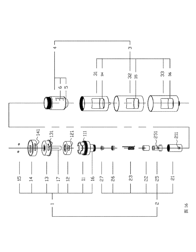
[0026] Figure 16 is an exploded view of an atomizer of an electronic cigarette
in
embodiment 7.
[0027] Figure 17 is a cutaway view of an atomizer of an electronic cigarette
in
embodiment 7.
6
CA 03062588 2019-11-06
SPECIFIC EMBODIMENTS
SPECIFIC EMBODIMENT 1
[0028] Hereinafter, specific embodiments of the invention shall be further
described
with reference to the accompanying drawings.
[0029] An atomizer of an electronic cigarette, as shown in figure 1,
comprises: an
airflow channel, a conductive line, an oil storage apparatus and an
atomization core (2);
wherein an atomization core (2) comprises a liquid seepage member (22), an
electric
heating body (23) and an atomization core housing (21), and the liquid seepage
member
(22) and the electric heating body (23)are arranged inside the atomization
core housing
(21); the liquid seepage member (22) is in communication with the oil storage
apparatus; the airflow channel is in communication with the atomization core
(2); the
oil storage apparatus is an oil storage bottle (4) which is integrally formed,
and a bottle
cover (1) is arranged on the oil storage bottle(4); the bottle cover
(1)comprises an cover
housing (13), an inner cover housing (11) and the insulation layer (12), in
which both
the cover housing (13) and the inner cover housing 11 are made of conductive
materials,
and insulation layer (12) is tubular to separates the cover housing (13) and
the inner
cover housing (11) so that the insulation is achieved; the bottle cover(1)
also includes
a gas and electricity conducting tube arranged below the bottle cover (1); the
atomization core housing (21) is detachably connected with the gas and
electricity
conducting tube; the gas and electricity conducting tube comprises a first
pipe (17) and
a second pipe (16 ), and the first pipe is arranged inside the second pipe; an
airflow
channel comprises the first pipe (17) and the breather pipe (18) formed
between the first
pipe(17) and the second pipe(16). It is shown on the figure that the breather
pipe (18 )is
an annular breather pipe; the first pipe (17) and the second pipe(16) are also
made of
conductive materials; a second pipe (16 )is integrally formed with an inner
cover
housing (11) and a first pipe (17) is integrally formed with an cover housing
(13); the
airflow channel comprises a first pipe (17) and a breather pipe (18), the
first pipe (17)
and the breather pipe (18) can reproduce the air inflow or air outgoing
towards the
atomization core (2); inside the oil storage bottle (4) is arranged the
atomization core
(2); the atomization core housing (21) is provided with oil inlet holes (211);
the
conductive line is conducted from the bottle cover(1) to the electric heating
body(23)
for heating, specifically, the cover housing (13) and the inner cover
housing(11) are
used for electrical conduction, and the electric heating body (23) will be
electrically
7
CA 03062588 2019-11-06
conductive as long as a voltage is applied between the cover housing (13) and
the inner
cover housing (11).
[0030] Since the embodiment 1 of bottle cover part is identical with that of
embodiment
2, reference is made to figure 3; wherein an adjusting ring (14) is sleeved
onto the cover
housing (13); air inlet holes (141) are provided on the adjusting ring (14);
on the bottle
cover (1) is provided an air inlet end which comprises the first air inlet
end(131)
arranged on the cover housing (13), the second air inlet end(121) on the
insulation
layer(12) and the third air inlet end on inner cover housing(11); the first
air inlet
end(131) are aligned with both the second air inlet (121) and the third air
inlet (111);
the cover housing(13) is provided with a pin(15) which is inserted through air
inlet
holes (141) and arranged onto the cover housing (13), when used, the adjusting
ring 14
can be rotated so that air inlet holes(141) are aligned with the first air
inlet end(131).
[0031] The atomization core (2) in the figure is relatively simple in design,
as shown in
figure 1. Combined with figure 3, it indicates that the atomization core 2 is
an assembly
of a liquid seepage member (22), an electric heating body (23) and an
atomization core
housing (21); wherein the atomization core housing (21) in cylindrical shape
is made
of conductive materials, and screw threads are internally provided at the
opening of the
cylinder; two ends of the helical electric heating body (23) are provided with
extensions; when it works, as shown in figure 1, one end of the electric
heating body(23)
contacts the first pipe (17) and the other end thereof contacts the bottom of
the
atomization core housing (21), and the electric heating body (23) will be
electrically
conductive whenever a voltage is applied between the cover housing (13) and
the inner
cover housing (11).
[0032] It should be noted that the conductive line may be any embodiment that
the
electric current is conducted from the bottle cover (1) to the electric
heating body (23),
and there are many embodiments to achieve this, such as the present embodiment
in
which the first pipe (17) and the second pipe (16) are made of electrically
conductive
materials, or adopt a wire to be directly connected with the electric heating
body (23).
SPECIFIC EMBODIMENT 2
[0033] The difference between present embodiment and the embodiment 1 lies in
that,
as shown in figures 2 and 3, below the bottle cover( 1) is further arranged a
cylinder
8
CA 03062588 2019-11-06
shell (3), the oil storage bottle (4) is arranged inside the cylinder shell
(3), and below
the cylinder shell (3) is arranged a joint (7); the cylinder shell (3)
comprises an outer
cylinder shell (33), an inner cylinder shell (31) and an insulation tube
(32);the insulating
tube (32) is arranged between the outer cylinder shell (33) and the inner
cylinder shell
(31); the conductive line comprises the outer cylinder shell (33), the inner
cylinder shell
(31), the cover housing (13) and the inner cover housing (11), and the outer
cylinder
shell (33), the inner cylinder shell (31), the cover housing (13) and the
inner cover
housing (11)are all made of conductive materials; the outer cylinder shell
(33) and the
inner cylinder shell (31) are electrically connected with the joint (7); one
end of the
outer cylinder shell (33) is electrically connected with the inner cover
housing (11); one
end of the inner cylinder shell (31) is electrically connected with the outer
cover housing
(13); one end of the electric heating body (23) is electrically connected with
the outer
cover housing (13) and the other end of the electric heating body (23) thereof
is
electrically connected with the inner cover housing (11).
100341 The conductive line in the present embodiment is from the outer
cylinder shell
(33), successively to the first pipe (17), the electric heating body (23), the
second pipe
(16), the inner cover housing (11) and then the inner cylinder shell (31);
wherein the
joint (7) arranged below the outer cylinder shell (33) and the inner cylinder
shell (31)
can be used cooperatively with a power supply; and using designs of the outer
cylinder
shell (33) and the inner cylinder shell (31) averts the situation that oil
storage apparatus
is placed inversely which is common among devices on the market, thereby
fundamentally solving the problem of oil leakage.
[0035] Viewing apertures are arranged on the cylinder shell, wherein the
viewing
apertures comprises an inner cylinder shell (31), an insulating tube (32), and
the outer
cylinder shell 33 which are respectively provided with the first viewing
aperture (34),
the second viewing aperture (35), and the third viewing aperture (36), and in
the
embodiment the oil storage bottle (4) is further provided with the scale marks
(6) so
that the residual oil quantity can be clearly seen while used.
[0036] In the present embodiment, at the bottom of the oil storage bottle (4)
is provided
a concave cylinder (5), wherein the size of the concave cylinder (5)is
identical with that
of the bottom of atomization core housing (21), and the concave cylinder (5)
wraps the
bottom of the atomization core housing (21), which is used for discharging the
tobacco
tar inside the concave cylinder (5) so that the oil inlet holes (211) can be
aligned with
9
CA 03062588 2019-11-06
the bottom of the oil storage bottle (4), and then all tobacco tar in the oil
storage bottle
(4)can pass through the oil inlet holes (211). In this way, the tobacco tar is
fully used
without waste.
SPECIFIC EMBODIMENT 3
[0037] The present embodiment using the simulated cigarettes differs from the
specific
embodiment 2, wherein the airflow channel is provided with a negative pressure
sensor
(8) and the negative pressure sensor (8) acts as follows, when a person
smokes, the
negative pressure will be produced on the airflow channel so that the negative
pressure
sensor will be connected with a power supply to heat the electric heating body
(23) and
the person will experience the feeling of smog once smoking.
SPECIFIC EMBODIMENT 4
[0038] The present embodiment differs from the specific embodiment 1, wherein
the
airflow channel of the electronic cigarette is no longer provided with the
first air inlet
end (131), the second air inlet end(121) and the third air inlet end(111), as
shown in
figure 5, an inner air inlet end (112 )is arranged on the inner cover housing
(11); an
outer air inlet end (71) is arranged on the joint (7); and the outer air inlet
end(71) is
communicated with the inner air inlet end(112) that communicates with the
airflow
channel. It can be noted from the present embodiment that the arrangement of
the air
flow channel in the bottle cover 1 can be varied and is not limited to any
position on
the bottle cover 1.
SPECIFIC EMBODIMENT 5
[0039] In the present embodiment, the structure that the cover housing and the
first pipe
is integrally formed is different from that in the embodiments 1-4, in
combination with
figures 6-10, wherein the cutting planes of figure 6 and figure 7 are
distributed in 90
degrees in space; it can be viewed that in the embodiments 1-4, the breather
pipe (18)
is used as an inlet pipe and the first pipe (17 ) is used as an outlet pipe;
wherein the first
pipe (17) communicates with an air inlet pipe (133), and the air inlet pipe
(133) showing
rectangular shape is arranged below the cover housing (13) and is communicated
with
first air inlet end (131); in the middle of cover housing (13)are provided air
outlet holes
(134); the air inlet pipe (133) passes through the bottom of the air outlet
hole (134); the
CA 03062588 2019-11-06
first pipe (17 )is arranged below the air inlet pipe (133); the axis of the
first pipe (17) is
consistent with that of the air outlet hole (134). As can be seen from the top
view of
figure 10 in conjunction with figures 8-9, after the air inlet pipe (133)
passes through
the bottom of the air outlet hole (134), the bottom round opening of the air
outlet hole
(134) is divided into two crescent-shaped and arc-shaped openings (132) which
are used
for discharging air, and the air in the breather pipe (18) enters the air
outlet hole (134)
through the arc-shaped openings (132); internal threads for connecting
cigarette holders
are arranged inside the air outlet hole (134). Combined with the previous five
embodiments, it can be seen that the breather tube (18) and the first pipe
(17) in the gas
and electricity conducting tube can be used either as an inlet air duct or an
outlet air
duct, and that the position of the inlet end is not limited to the cover
housing (13) or the
inner cover housing (11).
SPECIFIC EMBODIMENT 6
[0040] In the present embodiment, the structures of the first pipe and the
second pipe
of the gas and electricity conducting tube are greatly different from those in
the
embodiments 1 to 5; the first pipe is provided inside the second pipe in the
embodiments
1 to 5 while in present embodiment the first pipe (291) is provided outside
the second
pipe (293), wherein the first pipe (17) and the second pipe (16 )are separated
similar to
two semicircular long pipes; a cutaway view of the gas and electricity
conducting tube
as shown in figure 12 can be viewed that the first pipe (17), the second
conduit (93) and
the insulating tape (292) connecting the first pipe (17) and the second pipe
(16)
constitute a gas and electricity conducting tube with a circular section; as
shown in
figure 13, on the atomization core (2) are respectively provided an
atomization core air
inlet (294) and an atomization core air outlet (295); the first pipe (291) is
connected
with the atomization core air inlet (294), and the second pipe (293) is
connected with
the atomization core air outlet (295); the atomization core housing (21) is
made of
microporous ceramic; furthermore, the atomization core housing (21) is
provided with
a hole(296), which aims to increase the oil intake of the atomization core; as
shown in
figure 11, the section of the atomization core housing (21) is in a
substantially " U "
shape.
[0041] The embodiment aims to illustrate that the gas and electricity
conducting tube
not only has the arrangement that one tube is sleeved onto another, but also
has the
11
CA 03062588 2019-11-06
arrangement that one tube is arranged outside another. Thereby, in order to be
distinguished from the first and second tubes in the embodiments 1-5, it is
adopted that
the first pipe is arranged outside the second tube; and the term "outside" may
be
ambiguous, but it shall be regarded to be accurate in light of the distinction
between
present and previous embodiments.
SPECIFIC EMBODIMENT 7
[0042] The present embodiment is further described on the basis of the
specific
embodiment 2, the structure of an atomization core of an atomizer for
electronic
cigarettes in the embodiment is as follows: as shown in figure 14, an
atomization core
(2) comprises a liquid seepage member (22), an electric heating body (23) and
an
atomization core housing (21); wherein the inner tube (25) is arranged inside
the
atomization core housing 21; as shown in figure 15, a shim block (252) is
arranged at
the bottom of the inner tube (25); the inner wall of the inner tube (25) is
provided with
a long strip opening, and inside the inner tube (25) is provided the electric
heating body
(23) and a liquid seepage member (22); first oil inlet holes (211) and second
oil inlet
holes (251) are respectively distributed on the atomization core housing (21)
and the
inner tube (25), wherein first oil inlet holes (211) are aligned with second
oil inlet holes
(251); the liquid seepage member (22) is attached to the inner wall of the
inner tube
(25) in a tubular shape and arranged on the shim block (252); and the electric
heating
body (23) is arranged inside the tubular liquid seepage member (22) in a
spring shape.
[0043] The exploded view of the embodiment is as shown in figure 16, the
atomization
core housing (21) is in threaded connection with the second tube (16), wherein
both the
atomization core housing 21 and the inner tube 25 are made of conducting
materials
with good conductive performance, so that the conductive line can conduct from
the
second pipe (16) to the atomization core housing (21) and the inner cylinder
(25); in
order to improve the air tightness inside the atomization core and avoid short
circuits,
the nozzle of the inner tube(25) is provided with a seal ring (26) which
prevents direct
communication between the inner tube and the breather pipe (18); the seal ring
(26)
made of an insulator is concentric to a conductive component (27), and the
sealing ring
(26) is tightly sleeved onto the conductive component (27); one end of the
electric
heating body can be inserted inside between the seal ring (26) and the
conductive
element (27) because the seal ring (26) is elastic, and the other end contacts
the inner
12
CA 03062588 2019-11-06
tube (25); when the atomization core housing 21 is screwed with the second
pipe (16),
the first pipe (17) is butt jointed with the conductive element (27) and then
the
conductive element (27) is connected with the electric heating body (23) to
complete
circuit conduction; the working process of the gas and electricity conducting
tube is
described in detail in specific embodiments 1 and 2 and will not be described
in detail
again.
[0044] First of all, the inner tube (25) is closely attached to the inner wall
of the
atomization core housing (21) and the wall of the inner tube (25) is provided
with a
long strip opening (28) and second oil inlet holes (251), the liquid seepage
member (22)
communicates with the oil storage bottle (4) through first oil inlet holes
(211) and
second oil inlet holes(251) on the atomization core housing(21); and the
material of the
liquid seepage member (22) is not limited; the long strip opening (28) is used
for
inletting air and communicates with the breather pipe (18) inside the atomizer
of
electronic cigarettes, so that gas can flow along the long strip opening (28);
at the
bottom of the inner tube (25) is arranged a shim block (252) since it is
difficult for the
air out of the liquid seepage member (22) to flow inside as a result of the
textured
structure of it and the infiltrated tobacco tar, which aims to block up the
liquid seepage
member (22), so that the bottom of the liquid seepage member (22) can be
higher than
that of the long strip opening (28), and the air can flow into the inner side
of the liquid
seepage member (22) by passing through the intake (24) formed at the bottom of
the
inner tube (25).
[0045] Beneficial effects of the present invention are as follows: (1) the oil
storage
bottle can be conveniently used as a disposable product for timely
replacement; (2) the
atomization core integrates functions of electrical conduction, gas guiding
and oil
transmission, and longer oil paths such as oil guide cotton are eliminated;
the reaction
is more sensitive, smoke of new tobacco tar can be immediately used as soon as
oil is
replaced and in the meantime, it is more convenient to save oil and little oil
can be taken
away when replacing the atomization core; and (3) as for replacing oil bottle
and the
atomization core, under normal work the oil storage bottle keeps standing all
the time,
which perfectly prevents oil leakage caused by inversion of the liquid storage
bottle.
[0046] Finally, it should be explained that the above description is only to
illustrate the
technical solutions of the present invention instead of limiting the scope of
it. And those
skilled in the art will be able to make simple modifications or equivalent
alterations to
13
CA 03062588 2019-11-06
the technical solutions of the present invention without departing from the
spirit and
scope of the technical solution of the present invention as defined by the
following
claims.
14