Note: Descriptions are shown in the official language in which they were submitted.
ARRAY OF INDEPENDENTLY-CONTROLLABLE LASER DIODE BARS FOR
SCANNING A LINEAR ILLUMINATION PATTERN
CROSS-REFERENCE TO RELATED APPLICATION(S)
[0001] This application is a continuation-in-part of U.S. Application No.
15/936,095 filed
March 26, 2018 for "Scanned Linear Illumination of Distant Objects" by K.
Ramthun and J.
Pesik, which is incorporated herein by reference.
BACKGROUND
[0002] Each year, significant time and money are lost due to commercial
aircraft
accidents and incidents during ground operations, of which significant
portions occur during
taxiing maneuvers. During ground operations, aircraft share the taxiways with
other aircraft, fuel
vehicles, baggage carrying trains, mobile stairways and many other objects.
Aircrafts often taxi
to and/or from fixed buildings and other fixed objects. Should an aircraft
collide with any of
these objects, the aircraft must be repaired and recertified as capable of
operation. The cost of
repair and recertification, as well as the lost opportunity costs associated
with the aircraft being
unavailable for use can be very expensive.
[0003] Pilots are located in a central cockpit where they are well
positioned to observe
objects that are directly in front of the cabin of the aircraft. Objects that
are not located directly
in front of the cabin, however, can be more difficult to observe. Wings are
attached to the cabin
behind the cockpit and extend laterally from the cabin in both directions.
Some commercial and
some military aircraft have large wingspans, and so the wings on these
aircraft laterally extend a
great distance from the cabin and are thus positioned behind and out of the
field of view of the
cockpit. Some commercial and some military planes have engines that hang below
the wings of
the aircraft. Pilots, positioned in the cabin, can have difficulty knowing the
risk of collisions
between objects external to the aircraft and the wingtips and/or engines.
[0004] There are various types of on-ground operations that an aircraft
must perform at
an airport, each of which present different collision risks to the aircraft.
The taxi-in and taxi-out
phases require that the aircraft move between the runway and the terminal
gates, for example.
During taxi-in, the aircraft must first transition from the runway to a
taxiway and then to the
gateway. Sometimes, the taxiway can include an elaborate network of roads
requiring the aircraft
to travel over straight stretches as well as turns and transitions to/from the
taxiway. Some high-
CA 3062696 2019-11-25
speed taxi operation occurs on one-way taxiways dedicated to aircraft only.
During such high-
speed taxi operation, relatively distant objects located in the forward
direction of the aircraft
might present the greatest risk of collision to the aircraft. During low-speed
taxiing and gateway
approach, nearby objects in the vicinity of the wings and engine nacelles
might present the
greatest risk of collision to the aircraft.
SUMMARY
[0005] Apparatus and associated methods relate to a system for projecting a
linear beam of
light on a distant object. The system includes an array of independently-
controllable laser diode
bars distributed along a common axis. Each of the independently-controllable
laser diode bars is
configured to emit a beam of light in an emission direction orthogonal to the
common axis. The
emitted beam of light diverges about the emission direction at a first
divergence angle in the
plane including the emission direction and a fast-axis direction parallel to
the common axis. The
emitted beam of light diverges about the emission direction at a second
divergence angle in the
plane including the emission direction and a slow-axis direction. The second
divergence angle is
less than the first divergence angle.
BRIEF DESCRIPTION OF THE DRAWINGS
[0006] FIG. 1A is a schematic view of an aircraft collision alerting
system used by an
aircraft on a taxiway.
[0007] FIG. 1B depicts an image captured by a camera of the collision
alerting system
mounted to the aircraft depicted in FIG. 1A.
[0008] FIG. 2 is a perspective view of an embodiment of a linear
projector configured to
focus a linear beam at a predetermined distance.
[0009] FIG. 3 is a plan view of the linear projector depicted in FIG. 2.
[0010] FIG. 4 is a side-elevation view of the linear projector depicted
in FIGS. 2 and 3.
[0011] FIG. 5 is a schematic diagram of a single laser diode and a
projected beam
annotated with various beam characteristics.
[0012] FIG. 6 is a perspective view of an embodiment of a bar of laser
diodes, which can
provide the optical energy for a linear projector configured to focus a linear
beam at a
predetermined distance.
[0013] FIGS. 7A-7C depict linear projectors having various scanning
mechanisms.
2
CA 3062696 2019-11-25
[0014] FIGS. 8A-8B are side-elevation and plan views of an embodiment of
an array of
independently-controllable laser diode bars, which can be used to scan a
linear illumination
pattern upon a scene.
[0015] FIGS. 9A-9B are side-elevation and plan views of another
embodiment of an
array of independently-controllable laser diode bars, which can be used to
scan a linear
illumination pattern upon a scene.
DETAILED DESCRIPTION
[0016] Apparatus and associated methods relate to projecting a linear
beam of light onto
a distant object. One or more laser diodes are configured to emit one or more
elliptical beams of
light in an emission direction. If more than one laser diodes are used, they
are aligned so as to
have coplanar emission facets and common slow-axis and fast-axis directions,
which are
perpendicular to one another and to the emission direction. A first
cylindrical lens is configured
to receive the emitted beam(s) and to collimate each of the emitted beam(s) in
the fast-axis
direction perpendicular to a slow-axis direction. A second cylindrical lens is
configured to
receive the emitted beam(s) and to diverge the emitted beam(s) in the slow-
axis direction such
that if more than one beam is emitted, they are diverged so as to overlap one
another in the slow-
axis direction.
[0017] A linear beam of light is one that has a large ratio of beam
dimensions in
orthogonal directions transverse to the direction of propagation. For example,
if a light projector
projects a light beam in a direction parallel with a level ground surface and
the light beam has a
large azimuthal dimension and a small elevational dimension, such a light beam
illuminates a
rectangular area of a screen normal to the projection direction. The
illuminated rectangular area
can be called a horizontal line of illumination if the ratio between the
azimuthal dimension and
the elevational dimension is much greater than the elevational dimension. For
example, if the
ratio of the azimuthal dimension to the elevational dimension is greater than
50:1, 100:1, 200:1
or more, than the illuminated are is substantially linear. Similarly, if the
light projector projects a
light beam in a direction parallel with a level ground surface and the light
beam has a small
azimuthal dimension and a large elevational dimension, such a light beam again
illuminates a
rectangular area of a screen normal to the projection direction. But in this
scenario, the
illuminated rectangular area can be called a vertical line of illumination if
the ratio between the
3
CA 3062696 2019-11-25
elevational dimension and the azimuthal dimension is much greater than the
elevational
dimension.
[0018] Such linear beams of illumination can be used in the determination
of distance to
the object upon which the linear beams have been projected. For example, if
the beam is
projected from a first location of an aircraft, and a camera that is mounted
at a different location
on the aircraft captures images of the illumination pattern, these captured
images can contain
distance and/or range information regarding the distant objects reflecting the
linear beams. The
linear beam, for example, may appear broken in the captured images at image
locations
corresponding to illumination discontinuities ¨ edges of foreground objects.
Furthermore, if the
projected emitted linear beam is configured so as not to be coplanar with the
camera, then
triangulation can be used to determine the distances of the objects reflecting
the projected linear
beam. The locations and/or ranges can be calculated based on a location of a
projector, a location
of a camera or imager, and the pixel coordinates upon which the reflected
linear beam is focused.
[0019] The linear beam can be a pulse of light projected in a linear
pattern, such as, for
example, a pulse having a fixed elevation angle of projection but having an
azimuthal angle of
projection between +/- 25 degrees or more from the nominal direction. In some
embodiments,
the linear beam can be a collimated beam rastered or scanned in a direction
perpendicular to the
plane containing the linear beam. The linear beam is projected within a
controlled field of view.
This means that outside of the controlled field of view, substantially no
light energy is projected.
Herein the term linear beam indicates that light is projected within the field
of view in such a
manner that the projected light is not uniformly projected throughout the
solid-angle of
projection. For example, light will be primarily projected along certain
azimuthal and/or
elevational angles comprising a subset of the azimuthal and elevational angles
within the solid-
angle of light projection. Other subsets of the solid-angle of light
projection can be used for
linear beam projection.
[0020] In some embodiments, the linear beam can have a wavelength
corresponding to
infrared light and/or to an atmospheric absorption band. Using infrared light,
because it is outside
the visible spectrum, can minimize a distraction to a pilot who is taxiing the
aircraft. Using
infrared light that has a wavelength within an atmospheric absorption band can
permit low-
power projector illumination, as the illuminating power need not compete with
the sun's
illumination in such an absorption band. Knowing a first location on an
aircraft from which the
4
CA 3062696 2019-11-25
light is projected, a second location on an aircraft from which the reflection
is imaged, and a
pixel coordinate within the image corresponding to an object from which the
light is reflected
permits a calculation of the location and/or range of that reflecting object.
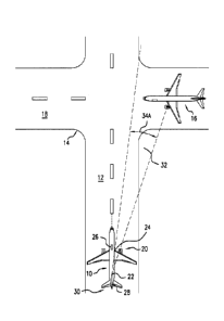
[0021] FIG. IA is a schematic view of an exemplary aircraft collision
alerting system
used by an aircraft on a taxiway. In FIG. 1A, first aircraft 10 is taxiing
along one-way taxiway
12. First aircraft 10 is approaching taxiway crossing 14. Second aircraft 16
is near the taxiway
crossing 14 on taxiway 18. First aircraft 10 is equipped with aircraft
collision alerting system 20.
Aircraft collision alerting system 20 includes linear projector 22, camera 24,
and a controller 26.
In the depicted embodiment, linear projector 22 is mounted on vertical
stabilizer 28 of tail 30.
Linear projector 22 is configured to project linear beam 32 onto a scene
external to first aircraft
10, thereby illuminating objects external to first aircraft 10. Linear
projector 22 can be mounted
at other locations on first aircraft 10 in other embodiments. Controller 26
controls and/or scans
the direction of projection, such that linear projector 22 projects linear
beam 32 within a
controlled direction of projection. In the depicted embodiment, the direction
of projection spans
various elevation angles of projection 34A.
[0022] The directions of projection can be orthogonal to the angular
direction of the
linear beam 32. For example, if linear beam 32 is in a plane that is roughly
parallel to a ground
surface (e.g., projecting horizontal lines on distant objects), then
controller 26 can be configured
to scan linear beam 32 in an elevational manner. Conversely, if linear beam 32
is in a plane that
is perpendicular to a ground surface (e.g., projecting vertical lines on
distant objects), then
controller 26 can be configured to scan linear beam 32 in an azimuthal manner.
By focusing
linear beam 32 so as to form lines of illumination on distant objects, the
power required for
projecting linear beam 32 can be reduced.
[0023] FIG. 1B depicts an image captured by a camera of the collision
alerting system
mounted to the aircraft depicted in FIG. 1A. In FIG. 1B, captured image 40A
has a field of view
commensurate with the solid-angle of projection of linear beam 32. Captured
image 40A depicts
second aircraft 16 on taxiway 18. Superimposed on taxiway 18 and second
aircraft 16 are lines
32A-32D generated by linear projector 22. Because linear projector 22 and
camera 24 are
mounted to first aircraft 10 at different locations, lines 32A-32D will have
discontinuities 42 in
captured image 40A where linear beam 32 encounters objects, such as second
aircraft 16. Such
CA 3062696 2019-11-25
discontinuities 42 in captured image 40A are indicative of differences in the
locations and/or
ranges of the objects from which linear beam 32 reflects.
[0024] Such aircraft collision alerting systems as described with
reference to FIGS. 1A-
1B have been disclosed by Rutkiewicz et al., in US patent application No.
15/489381, titled
"Method and System for Aircraft Strike Alerting, filed April 17, 2017, the
entire specification of
which is hereby incorporated by reference.
[0025] FIG. 2 is a perspective view of an embodiment of a linear
projector configured to
focus a linear beam at a predetermined distance. In FIG. 2, linear projector
22 includes laser
diode bar 44, first convex cylindrical lens 45, first concave cylindrical lens
46, second concave
cylindrical lens 48, and second convex cylindrical lens 50. Laser diode bar 44
includes a
plurality of laser diodes all aligned so as to each emit a beam in emission
direction DE normal to
emission plane PE, which is coplanar with emission facets of each of the
plurality of laser diodes
of laser diode bar 44. Each of the laser diodes has both a fast-axis direction
DFA and a slow-axis
direction DsA that are approximately the same as the fast-axis direction DFA
and slow-axis
direction DSA, respectively, pertaining to each of the other of the plurality
laser diodes of laser
diode bar 44. Various embodiments can use more or fewer laser diodes,
including one
embodiment in which a single laser diode can be used to emit an optical beam.
Fast-axis
direction DFA, slow-axis direction DsA, and emission direction DE are all
orthogonal one to
another, in the depicted embodiment.
[0026] Simultaneous pulses of optical energy are emitted by each of the
plurality of laser
diodes of laser diode bar 44. The simultaneously emitted pulses of optical
energy are emitted
from emission facets located along transverse axis 52 within emission plane
PE. The
simultaneously emitted pulses of optical energy form linear emission beam 54
having divergence
in both slow-axis direction DsA and fast-axis direction DFA. Divergences in
the slow-axis
direction are divergences about the emission direction in the plane including
the emission
direction and the slow-axis direction. Divergences in the fast-axis direction
are divergences
about the emission direction in the plane including the emission direction and
the fast-axis
direction. In the FIG. 2 depiction, linear emission beam 54 is shown as having
a 60 angle of
divergence as measured before lens correction.
[0027] Linear emission beam 54 is then received by first convex
cylindrical lens 45. First
convex cylindrical lens 45 is convex in a fast-axis direction DFA and planar
in a slow-axis
6
CA 3062696 2019-11-25
direction DSA. Such a lens can be called a piano-convex cylindrical lens.
Because the convexity
of first convex cylindrical lens 45 is aligned with fast-axis direction DFA,
first convex cylindrical
lens 45 is configured to refract linear emission beam 54 so as to change the
divergence of linear
emission beam 54 in the fast-axis direction. For piano-convex cylindrical
lenses, the beam
divergence is decreased by refraction. Thus, first convex cylindrical lens 45
decreases the
divergence of received linear emission beam 54 in the fast-axis direction. In
some embodiments,
first convex cylindrical lens 45 is mounted directly onto laser diode bar 44.
Some embodiments
do not have first convex cylindrical lens 45.
100281 First concave cylindrical lens 46 is configured to receive linear
emission beam 54
after it is refracted by first convex cylindrical lens 45. First concave
cylindrical lens 46 is
concave in fast-axis direction DFA and planar in slow-axis direction DsA. Such
a lens can be
called a piano-concave cylindrical lens. Because the concavity of first
concave cylindrical lens
46 is aligned with fast-axis direction DFA, first concave cylindrical lens 46
is configured to
refract linear emission beam 54 so as to change the divergence of linear
emission beam 54 in the
fast-axis direction. For plano-concave cylindrical lenses, the beam divergence
is increased by
refraction. Thus, first concave cylindrical lens 46 increases the divergence
of received linear
emission beam 54 in the fast-axis direction. In some embodiments, the first
lens can be a
cylindrical lens such as the piano-concave cylindrical lens depicted in FIG.
2. In other
embodiments, the first lens can be a spherical or an aspherical lens.
100291 Second concave cylindrical lens 48 is configured to receive linear
emission beam
54 after it is refracted by first concave cylindrical lens 46. The depicted
location of second
concave cylindrical lens 48 follows first concave cylindrical lens 46, but in
other embodiments
second concave cylindrical lens can precede first concave cylindrical lens 46.
Second concave
cylindrical lens 48 is concave in the slow-axis direction DsA and planar in
the fast-axis direction
DFA. Because the concavity of second concave cylindrical lens 48 is aligned
with slow-axis
direction DsA, second concave cylindrical lens 48 is configured to refract
linear emission beam
54 so as to change the divergence about the emission direction in the plane
including the
emission direction and a slow-axis direction. In the depicted embodiment,
second concave
cylindrical lens 48 increases the divergence of linear emission beam 54 in the
slow-axis
direction. By orienting the concavity of second concave cylindrical lens 48 in
the slow-axis
direction, which is the direction in which the plurality of laser diodes of
laser diode bar 44 are
7
CA 3062696 2019-11-25
aligned, the pulses of optical energy emitted by the individual laser diodes
of laser diode bar 44
will overlap the optical energy emitted by neighboring laser diodes of laser
diode bar 44. Such
overlap can result in a 100% fill factor in the projected linear beam of
light. In some
embodiments, the divergence will not result in 100% fill factor yielding a
dashed linear beam of
light or a linear beam having periodic intensity variation.
[0030] Second convex cylindrical lens 50 is configured to receive linear
emission beam
54 after it is refracted by second concave cylindrical lens 48. Second convex
cylindrical lens 50
is convex in the fast-axis direction DFA and planar in the slow-axis direction
Dsp. Such a lens can
be called a plano-convex cylindrical lens. Because the convexity of second
convex cylindrical
lens 50 is aligned with fast-axis direction DFA, second convex cylindrical
lens 50 is configured to
refract linear emission beam 54 so as to change the divergence about the
emission direction in
the plane including the emission direction and a fast-axis direction. For
piano-convex cylindrical
lenses, the beam divergence is decreased by refraction. Thus, second convex
cylindrical lens 50
decreases the divergence of received linear emission beam 54 in the fast-axis
direction. Although
the FIG. 2 embodiment depicts piano-convex and piano-concave cylindrical
lenses, various
embodiments can use other types of convex and concave cylindrical lenses.
[0031] In some embodiments, the combination of first convex cylindrical
lens 45, first
concave cylindrical lens 46 and second convex cylindrical lens 50 are
configured to collimate
and/or focus linear emission beam 54 in the fast-axis direction. In some
embodiments more or
fewer cylindrical lenses can be configured to collimate and/or focus linear
emission beam 54 in
the fast-axis direction. In other embodiments, first convex cylindrical lens
45, first concave
cylindrical lens 46 and second convex cylindrical lens 50 are configured to
focus linear emission
beam 54 in the fast-axis direction so that at a predetermined distance from
linear projector 22,
linear emission beam 54 has small full-width half-magnitude (FWHM) width in
the fast-axis
direction and large FWHM length in the slow-axis direction, thereby earning
its name of "linear
emission beam." In some embodiments, such a narrow beam in the fast-axis
direction can have a
FWHM width of less than 10 centimeters, 5 centimeters, 3 centimeters, or 2
centimeter in the
fast-axis width. At the predetermined distance at which linear emission beam
54 is focused,
linear emission beam 54 can have a large slow-axis length. For practical
purposes the length of
the beam can be considered to be very long in the slow-axis direction, having
a length to width
8
CA 3062696 2019-11-25
ratio exceeding 100:1, 1000:1, or 10,000:1 at a distance from emission where
the beam is
focused, so as not to impose a slow-axis barrier to passage of the linear
emission beam 54.
[0032] For example, in one embodiment, linear projector 22 can be
configured to focus
linear emission beam 54 in the fast-axis direction DFA at a predetermined
distance of 150 meters
while diverging linear emission beam 54 at 500 in the slow-axis direction Dsp.
At the
predetermined distance, the FWHM of linear emission beam 54 can be less than
1.5 centimeters
in the fast-axis direction DFA and can be about 140 meters in the slow-axis
direction Dsp. The
predetermined distance at which a ratio of the length to width of the beam can
vary in
accordance with beam illumination specifications. For example, the beam may be
focused and
diverged in such a manner as to cause a FWHM length to width ratio to exceed
50:1, 100:1,
500:1 or 1000:1 at a distance of 50, 80, 100, 120, 200, or 300 meters from
linear projector 22, for
example.
[0033] Because detection of linear emission beam 54 can be used to
determine range
and/or location information of objects from which the beam reflects, linear
emission beam 54
should be detectable by a detector. To ensure that linear emission beam 54 is
detectable, linear
emission beam 54 should have intensity greater than the solar irradiance level
present during
daylight conditions. The solar irradiance can be as high as 100,000 lux or 1
kilowatt per square
meter on bright sunny days. Focusing linear emission beam 54 in such a linear
fashion as
described above can provide local intensities of linear emission beam 54 that
are in excess of the
solar irradiance, at least for a portion of the solar spectrum that includes
the emission spectrum
of linear emission beam 54. Filtering the detection spectrum to include only
the emission
spectrum and a guard band on either side of the emission spectrum further
improves detectability
of linear emission beam 54.
[0034] In some embodiments, linear emission beam 54 is in the infrared
band of the
optical spectrum. Such an emission spectrum can be used to illuminate distant
objects while
remaining undetectable to humans so as not to distract pilots and ground crew.
In some
embodiments, linear emission beam 54 can have a spectral bandwidth as small as
2.5 nm.
[0035] FIG. 3 is a plan view of the linear projector depicted in FIG. 2.
The plan view
orientation of FIG. 3 is helpful in depicting the operation of linear
projector 22 in the slow-axis
direction Dsp. In FIG. 3, linear projector 22 includes laser diode bar 44,
first convex cylindrical
lens 45, first concave cylindrical lens 46, second concave cylindrical lens
48, and second convex
9
CA 3062696 2019-11-25
cylindrical lens 50. Laser diode bar 44 includes a plurality of laser diodes
all aligned so as to
each emit a beam in emission direction DE. The plurality of laser diodes of
laser diode bar 44
generates simultaneous pulses of optical energy from each of the plurality of
laser diodes so as to
emit laser beams from emission facets located along transverse axis 52. In the
FIG. 3 plan view,
only divergence in the slow-axis direction DSA (i.e., about the emission
direction in the plane
including the emission direction and a fast-axis direction) of linear emission
beam 54 can be
depicted. The FWHM length L in the slow-axis direction increases with
increasing distance from
linear projector 22 due to the positive beam divergence in the slow-axis
direction.
[0036] Linear emission beam 54 is received by first convex cylindrical
lens 45. First
convex cylindrical lens 45 is planar in slow-axis direction DSA. Because of
the planarity of first
convex cylindrical lens 45 in the slow-axis direction DSA, first convex
cylindrical lens 45 doesn't
significantly change the divergence of linear emission beam 54 in the slow-
axis direction DSA.
[0037] First concave cylindrical lens 46 is configured to receive linear
emission beam 54
after it is refracted by first convex cylindrical lens 45. First concave
cylindrical lens 46 is planar
in slow-axis direction DSA. Because of the planarity of first concave
cylindrical lens 46 in the
slow-axis direction DSA, first concave cylindrical lens 46 doesn't
significantly change the
divergence in of linear emission beam 54 in the slow-axis direction DSA.
[0038] Second concave cylindrical lens 48 is configured to receive linear
emission beam
54 after it is refracted by first concave cylindrical lens 46. Second concave
cylindrical lens 48 is
concave in the slow-axis direction DSA. Because the concavity of second
concave cylindrical lens
48 is aligned with slow-axis direction DSA, second concave cylindrical lens 48
is configured to
refract linear emission beam 54 so as to change the divergence in the slow-
axis direction. In the
depicted embodiment, second concave cylindrical lens 48 increases the
divergence of linear
emission beam 54 in the slow-axis direction. By orienting the concavity of
second concave
cylindrical lens 48 in the slow-axis direction, which is the direction in
which the plurality of laser
diodes of laser diode bar 44 are aligned, the pulses of optical energy emitted
by the individual
laser diodes of laser diode bar 44 will overlap the optical energy emitted by
neighboring laser
diodes of laser diode bar 44.
[0039] Second convex cylindrical lens 50 is configured to receive linear
emission beam
54 after it is refracted by second concave cylindrical lens 48. Second convex
cylindrical lens 50
is planar in the slow-axis direction DSA. Because of the planarity of second
convex cylindrical
CA 3062696 2019-11-25
lens 50 in the slow-axis direction DSA, second convex cylindrical lens 50
doesn't significantly
change the divergence in of linear emission beam 54 in the slow-axis direction
DSA.
[0040] FIG. 4 is a side-elevation view of the linear projector depicted
in FIGS. 2 and 3.
The side-elevation view orientation of FIG. 4 is helpful in depicting the
operation of linear
projector 22 in the fast-axis direction DFA. In FIG. 4, linear projector 22
includes laser diode bar
44, first convex cylindrical lens 45, first concave cylindrical lens 46,
second concave cylindrical
lens 48, and second convex cylindrical lens 50. Laser diode bar 44 includes a
plurality of laser
diodes all aligned so that, from the side-elevation perspective, the beam is
emitted from a point
and in emission direction DE. In the FIG. 4 side-elevation view, only
divergence in the fast-axis
direction DFA (i.e., about the emission direction in the plane including the
emission direction and
a fast-axis direction) of linear emission beam 54 can be depicted. The FWHM
width W in the
fast-axis direction doesn't significantly increase with distance from linear
projector 22 due to the
non-positive beam divergence in the fast-axis direction. For collimated beams,
the angle of
divergence in the fast-axis direction is approximately zero (e.g., between +/-
a few degrees), and
for focused beams, the angle of divergence in the fast-axis direction is
negative. Thus, the beam
narrows with increasing distance until a projection distance approximately
equal to a focal point
of the optical system. Beyond such a focal point, the beam width W increases
having a
divergence angle therefrom approximately opposite (i.e., additive inverse) the
angle of
divergence as measured at the focusing lens.
[0041] Linear emission beam 54 is received by first convex cylindrical
lens 45. First
convex cylindrical lens 45 is convex in a fast-axis direction DFA. Because the
convexity of first
convex cylindrical lens 45 is aligned with fast-axis direction DFA, first
convex cylindrical lens 45
is configured to refract linear emission beam 54 so as to change the
divergence of linear emission
beam 54 in the fast-axis direction DFA. For such a convex lens configuration,
the beam
divergence is decreased by refraction. Thus, first convex cylindrical lens 45
decreases the
divergence of received linear emission beam 54 in the fast-axis direction.
First convex
cylindrical lens can be used in conjunction with first concave cylindrical
lens 46 and/or second
convex cylindrical lens 50 to collimate and/or focus linear emission beam 54
in a fast-axis
direction, as will be described below.
[0042] First concave cylindrical lens 46 is configured to receive linear
emission beam 54
after it is refracted by first convex cylindrical lens 45. First concave
cylindrical lens 46 is
11
CA 3062696 2019-11-25
concave in fast-axis direction DFA. Because the concavity of first concave
cylindrical lens 46 is
aligned with fast-axis direction DFA, first concave cylindrical lens 46 is
configured to refract
linear emission beam 54 so as to change the divergence of linear emission beam
54 in the fast-
axis direction DFA. For such a concave lens configuration, the beam divergence
is increased by
refraction. Thus, first concave cylindrical lens 46 increases the divergence
of received linear
emission beam 54 in the fast-axis direction.
[0043] Second concave cylindrical lens 48 is configured to receive linear
emission beam
54 after it is refracted by first concave cylindrical lens 46. Second concave
cylindrical lens 48 is
planar in the fast-axis direction DFA. Because the planarity of second concave
cylindrical lens 48
in the fast-axis direction DFA, second concave cylindrical lens 48 doesn't
significantly change the
divergence in of linear emission beam 54 in the fast-axis direction DFA.
[0044] Second convex cylindrical lens 50 is configured to receive linear
emission beam
54 after it is refracted by first concave cylindrical lens 46. Second convex
cylindrical lens 50 is
convex in the fast-axis direction DFA. Because the convexity of second convex
cylindrical lens
50 is aligned with fast-axis direction DFA, second convex cylindrical lens 50
is configured to
refract linear emission beam 54 so as to change the divergence of linear
emission beam 54 in the
fast-axis direction DFA. For such a convex lens configuration, the beam
divergence is decreased
by refraction. Thus, second convex cylindrical lens 50 decreases the
divergence of received
linear emission beam 54 in the fast-axis direction.
[0045] In some embodiments, the combination of first concave cylindrical
lens 46 and
second convex cylindrical lens 50 are configured to collimate and/or focus
linear emission beam
54 in the fast-axis direction. In other embodiments, first concave cylindrical
lens 46 and second
convex cylindrical lens 50 are configured to focus linear emission beam 54 in
the fast-axis
direction so that at a predetermined distance from linear projector 22, linear
emission beam 54
has a small width in the fast-axis direction. For example, the full-width half-
magnitude (FWHM)
width of the optical energy can be equal to or less than 5 centimeters, 3
centimeters, or 2
centimeter in the fast-axis direction. At the predetermined distance at which
linear emission
beam 54 is focused, linear emission beam 54 can have a large slow-axis
direction.
[0046] FIG. 5 is a schematic diagram of a single laser diode and a
projected beam
annotated with various beam characteristics. In FIG. 5, laser diode 44A is one
of the plurality of
laser diodes of laser diode bar 44 depicted in FIGS. 2-4. Laser diode 44A
includes
12
CA 3062696 2019-11-25
semiconductor portion 56 in which is formed active layer 58. Back facet 60 and
emission facet
62 are formed on opposite sides of active layer 58. Back facet 60 can be
coated with a coating
that causes near-total internal reflection of optical energy. Laser diode 44A
is shown emitting
pulse of optical energy 54A in emission direction DE normal to emission facet
62.
[0047] Pulse of optical energy 54A is elliptical, astigmatic, and has
large divergence.
Pulse of optical energy 54A is generated in active layer 58 of semiconductor
portion 56 and is
emitted from emission facet 62 at one end of the active layer 58. Because
active layer 58 of laser
diode 44A has a rectangular shaped cross section ¨ thin in the fast-axis
direction DFA and wide in
the slow-axis direction ¨ DSA emitted pulse of optical energy 54A at emission
facet 62 has an
elliptical shape as depicted. For example, in the depicted embodiment, pulse
of optical energy
54A emitted at emission facet 62 is about five microns in the direction
vertical to active layer 58
(the fast-axis direction DFA) and hundreds of microns in the direction
horizontal to active layer
58 (the slow-axis direction DSA).
[0048] Various embodiments use various sources of light emissions. For
example,
various types, geometries of laser diodes can be used to generate a linear
beam of light using the
lens configurations described herein. Embodiments in which the laser diodes
have different
dimensions, the ratio of the slow-axis beam length to the fast-axis beam width
can be as large as
50:1, 100:1 or even greater. Furthermore, non-laser-diode light sources, such
as traditional lasers
or vertical-cavity surface emission lasers can also be used to generate a
linear beam of light using
the lens configurations described herein.
[0049] The beam divergence, however, is greater in the fast-axis
direction DFA (i.e.,
about the emission direction in the plane including the emission direction and
the fast-axis
direction) than in the slow-axis direction DSA (i.e., about the emission
direction in the plane
including the emission direction and the slow-axis direction). This is
indicated by the first
divergence angle 01 (i.e., the divergence in the fast-axis direction) being
greater than the second
divergence angle 02 (i.e., the divergence in the slow-axis direction). Thus,
as pulse of optical
energy 54A propagates away from emission facet 62, the ratio of the slow-axis
beam length to
the fast-axis beam width will continuously decrease. For example, the full
width half magnitude
(FWHM) divergent angle in the slow-axis direction DSA can be between 6 -12 ,
while the
FWHM divergent angle in the fast-axis direction DFA can be between 15 -40 .
13
CA 3062696 2019-11-25
[0050] FIG. 6 is a perspective view of an embodiment of a bar of laser
diodes, which can
provide the optical energy for a linear projector configured to focus a linear
beam at a
predetermined distance. In FIG. 6, laser diode bar 44 includes laser diodes
44A-44E. Laser
diodes 44A-44E generate beams of optical energy 54A-54E, respectively. Each of
the generated
pulses of optical energy 54A-54E is emitted in emission direction DE. As each
of the emitted
pulses of optical energy propagates, divergence in both the slow-axis
direction DSA and in the
fast-axis direction DFA occurs. Because divergence in the fast-axis direction
DFA is greater than
divergence in the slow-axis direction DSA, the far-field elliptical profile of
the pulses are different
than the profile of the pulses at the emission facets.
[0051] Laser diodes 44A-44E are aligned along a transverse axis that is
parallel to the
slow-axis direction. Although the divergence angle in the slow-axis direction
DSA is small (e.g.,
less than 200 is not uncommon), optical pulses of energy 54A-54E will
eventually combine to
form a single linear emission beam 54, even without lensing. Combined beam 54,
however, will
only have a divergence in the slow-axis direction DSA equal to the divergence
in the slow-axis
direction DSA of each of the optical pulses of energy 54A-54E. To increase the
divergence in the
slow-axis direction a concave cylindrical lens can be used, as shown above by
second concave
cylindrical lens 48, depicted in FIG. 2. For even greater divergences,
cylindrical lens 48 can be a
combination of two or more concave cylindrical lenses. Such lens
configurations can provide
slow-axis divergence up to 180 degrees.
[0052] Combined beam 54 has a greater divergence in the fast-axis
direction DFA than in
the slow-axis direction DSA. A plano-convex lens, such as second convex
cylindrical lens 50
depicted in FIG. 2, can be used to collimate and/or focus combined beam 54.
Once so collimated
or focused, combined beam 54 can illuminate distant objects with intensities
that exceed the
solar irradiance, at least over a limited bandwidth. Such a projector can thus
be used in broad
daylight to determined range and or location information of objects external
to an aircraft.
[0053] FIGS. 7A-7C depict linear projectors having various scanning
mechanisms. In
FIG. 7A, linear projector 22A has scanning mechanism 64A, which is configured
to
mechanically scan linear beam 32A in a fast-axis direction. Scanning mechanism
64A includes
rotational member 66, which rotates linear projector 22A about pivot axis 68A.
In some
embodiments, pivot axis 68A can be parallel to the slow-axis direction DSA, as
depicted.
14
CA 3062696 2019-11-25
[0054] In FIG. 7B, linear projector 22B has scanning mechanism 64B, which
is
configured to optically scan linear beam 32B by reflecting linear beam 32B via
rotatable mirror
70. Rotatable mirror 70 is interposed in the path of linear beam 32B. Scanning
mechanism 64B is
configured to rotate rotatable mirror 70 about rotation axis 68B that is
parallel to the slow-axis
direction DSA Rotatable mirror 70 scans linear beam 32B in the fast-axis
direction (i.e.,
perpendicular to the linear beam 32B) as it is rotated about rotation axis
68B.
[0055] In FIG. 7C, linear projector 22C has electronic scanning
capability. Linear
projector 22C includes an array of laser diode bar 72 that includes rows of
laser diodes 44A-44Z.
Each of the laser diodes in a particular row 44A-44Z is aligned along a fast-
axis direction with
the other laser diodes in that particular row 44A-44Z. Each of the laser diode
rows 44A-44Z can
be independently energized in turn. In the depicted embodiment laser diode row
44N is
energized. Each of the laser diode rows 44A-44Z are configured to generate a
linear beam 32C
of light that is collimated and/or focused by cylindrical lenses 45A-45N, 46
and 50 in a fast-axis
direction DFA. The linear beam emitted by each row of laser diodes 44A-44Z is
then diverged in
a slow axis direction DSA, by cylindrical lens 48. For example, the laser
diode rows 44A-44Z
can be energized in a sequence from top row 44A to bottom row 44Z, so as to
generate a
corresponding sequence of linear beams focused at different angles of
elevation with respect to
linear projector 22C.
[0056] FIGS. 8A-8B are side-elevation and plan views of an embodiment of
an array of
independently-controllable laser diode bars, which can be used to scan a
linear illumination
pattern upon a scene. In FIGS. 8A and 8B, laser diode array 100 includes
independently-
controllable laser diode bars 102A-102D distributed along a common axis As,.
Independently-
controllable laser diode bars 102A-102D are aligned so that each of
independently-controllable
laser diode bars 102A-102D is configured to emit light in a common emission
direction DE
orthogonal to the common axis Av.
[0057] The beam of light emitted by each of independently-controllable
laser diode bars
102A-102D diverges at a first divergence angle in a fast-axis direction DFA
parallel to the
common axis Ay and orthogonal to the emission direction DE, and diverges at a
second
divergence angle in a slow-axis direction DsA perpendicular both to the common
axis Av and to
the emission direction DE. The second divergence angle is less than the first
divergence angle, as
is the nature of fast-axis illumination patterns and slow-axis illumination
patterns.
CA 3062696 2019-11-25
[0058] Divergence in the fast-axis direction means that the divergence of
light about the
emission direction in the plane including the emission direction and the fast-
axis direction. In
other words, it means that a transverse dimension of the light beam parallel
to the fast-axis
direction increases as the light beam propagates in the direction of emission.
Similarly,
divergence in the slow-axis direction means that the divergence of light about
the emission
direction in the plane including the emission direction and the slow-axis
direction. In other
words, it means that a transverse dimension of the light beam parallel to the
slow-axis direction
increases as the light beam propagates in the direction of emission.
[0059] Laser diode array 100 is formed as a stack of a plurality of plate
members 104A-
104D. Each of the plurality of plate members 104A-104D has a corresponding one
of the array
of independently-controllable laser diode bars 102A-102D affixed thereto. The
stack of
alternating plate members and insulative spacers are aligned such that
emission faces, from
which the beams of light are emitted, of the array of independently-
controllable laser diode bars
102A-102D, are coplanar.
[0060] A plurality of insulative spacers 106A-106D provides electrical
isolation between
adjacent pairs (e.g., between plate members 104B and 104C, etc.) of plate
members 104A-104D.
Such electrical isolation is obtained by interposing one of insulative spacers
106A-106D between
the adjacent pairs of the plurality of plate members 104A-104D. Each of the
plurality of
insulative spacers 106A-106D isolates the adjacent pairs of the plurality of
plate members 104A-
104D from one another, so that independently-controllable laser diode bars
102A-102D affixed
thereto can be independently energized.
[0061] Each of the plurality of plate members 104A-104D has first and
second electrical
contacts 108A-108D and 110A-110D, respectively. Each of first electrical
contacts 108A-108D
is in conductive communication with an anode of a corresponding one of the
independently-
controllable laser diode bar 102A-102D. Each of second electrical contacts
110A-110D is in
conductive communication with a cathode of a corresponding one of the
independently-
controllable laser diode bar 102A-102D.
[0062] Plate members 104A-104B have different longitudinal dimensions in
the emission
direction DE such that the stack of alternating plate members 104A-104D and
insulative spacers
106A-106D form a staircase profile on a contact end opposite an emission end
at which the
emission faces reside. First and second electrical contacts 108A-108D and 110A-
110D,
16
CA 3062696 2019-11-25
respectively, are formed on exposed steps of the staircase profile, thereby
permitting electrical
connections thereto. Because pairs of first and second electrical contacts
108A and 110A, 108B
and 110B, 108C and 110C, and 108D and 110D are electrically isolated from one
another, each
of laser diode bars 102A-102D can be independently energized by providing an
energizing
electrical signal to the corresponding contact pair. In some embodiments
switches and/or
transistors can be configured to provide switched power to each of the pairs
of first and second
electrical contacts 108A and 110A, 108B and 110B, 108C and 110C, and 108D and
110D,
thereby facilitating independent control of laser diode bars 102A-102D.
[0063] FIGS. 9A-9B are side-elevation and plan views of another
embodiment of an
array of independently-controllable laser diode bars, which can be used to
scan a linear
illumination pattern upon a scene. In FIGS. 9A and 9B, laser diode array 110
includes
independently-controllable laser diode bars 112A-112E distributed along a
common axis AL.
Independently-controllable laser diode bars 112A-112E are aligned so that each
of
independently-controllable laser diode bars 112A-112E is configured to emit
light in a common
emission direction DE orthogonal to the common axis AL.
[0064] The beam of light emitted by each of independently-controllable
laser diode bars
112A-112E diverges at a first divergence angle in a fast-axis direction DFA
parallel to the
common axis AL and orthogonal to the emission direction DE, and diverges at a
second
divergence angle in a slow-axis direction DsA perpendicular both to the common
axis AL and to
the emission direction DE. The second divergence angle is less than the first
divergence angle, as
is the nature of fast-axis illumination patterns and slow-axis illumination
patterns.
[0065] Laser diode array 110 is attached to or formed with single plate
member 114
having top and bottom surfaces STOP and SBoT extending between lateral and
transverse ends
ELATI-ELAT2 and ETRANI-ETRAN2.= In some embodiments, top surface STOP is
substantially coplanar
with emission faces, from which the beams of light are emitted, of the array
of independently-
controllable laser diode bars. In other embodiments, such as the depicted
embodiment,
independently-controllable laser diode bars 112A-112E are affixed to top
surface STOP, such that
the emitted beams of light of the array of independently-controllable laser
diode bars, are all
directed in the emission direction.
[0066] First and second electrical contacts 118A-108E and 120A-120E,
respectively, are
formed on single plate member 114. Each of first electrical contacts 118A-108E
is in conductive
17
CA 3062696 2019-11-25
communication with an anode of a corresponding one of the independently-
controllable laser
diode bar 112A-112E. Each of second electrical contacts 120A-120E is in
conductive
communication with a cathode of a corresponding one of the independently-
controllable laser
diode bar 112A-112E. In the depicted embodiment, each of independently-
controllable laser
diode bars 112A-112E is affixed to a copper-tungsten CuW substrate, so as to
provide heat
dissipation therefrom
[0067] Discussion of Possible Embodiments
[0068] The following are non-exclusive descriptions of possible
embodiments of the
present invention.
[0069] Apparatus and associated methods relate to a system for projecting
a linear beam
of light on a distant object. The system includes an array of independently-
controllable laser
diode bars distributed along a common axis. Each of the independently-
controllable laser diode
bars is configured to emit a beam of light in an emission direction orthogonal
to the common
axis. The emitted beam of light diverges about the emission direction at a
first divergence angle
in the plane including the emission direction and a fast-axis direction. The
emitted beam of light
also diverges about the emission direction at a second divergence angle in the
plane including the
emission direction and a slow-axis direction. The second divergence angle is
less than the first
divergence angle.
[0070] The system of the preceding paragraph can optionally include,
additionally and/or
alternatively, any one or more of the following features, configurations
and/or additional
components:
[0071] A further embodiment of the foregoing system, wherein each of the
independently-controllable laser diode bars includes an anode, a cathode, a
first electrical contact
in conductive communication with the anode, and a second electrical contact in
conductive
communication with the cathode.
[0072] A further embodiment of any of the foregoing systems, wherein each
of the
independently-controllable laser diode bars is configured to emit the beam of
light in response to
an electrical signal supplied to the first and second contacts.
[0073] A further embodiment of any of the foregoing systems further
includes a plurality
of plate members, each having a corresponding one of the array of
independently-controllable
laser diode bars affixed thereto, and a plurality of insulative spacers. Each
of the plurality of
18
CA 3062696 2019-11-25
insulative spacers is interposed between adjacent ones of the plurality of
plate members, thereby
forming a stack of alternating plate members and insulative spacers. Each of
the plurality of
insulative spacers electrically isolates adjacent ones of the plurality of
plate members from one
another.
[0074] A further embodiment of any of the foregoing systems, wherein the
stack of
alternating plate members and insulative spacers are aligned such that, at an
emission end,
emission faces, from which the beams of light are emitted, of the array of
independently-
controllable laser diode bars, are coplanar.
[0075] A further embodiment of any of the foregoing systems, wherein the
plurality of
plate members have different longitudinal dimensions in the emission direction
such that the
stack of alternating plate members and insulative spacers form a staircase
profile on a contact
end opposite an emission end at which the emission faces reside. The first and
second electrical
contacts are formed on exposed steps of the staircase profile, thereby
permitting electrical
connections thereto.
[0076] A further embodiment of any of the foregoing systems, wherein the
array of
independently-controllable laser diode bars comprises a single plate member
having top and
bottom surfaces extending from lateral and transverse ends. The array of
independently-
controllable laser diode bars is affixed to the top surface of the single
plate member.
[0077] A further embodiment of any of the foregoing systems, wherein each
of the array
of independently-controllable laser diode bars is affixed to a copper-tungsten
substrate, so as to
provide heat dissipation therefrom.
[0078] A further embodiment of any of the foregoing systems, wherein each
of the
independently-controllable laser diode bars comprises a plurality of
independently-controllable
laser diode bars distributed along a common transverse axis parallel to the
slow-axis direction.
[0079] A further embodiment of any of the foregoing systems further
includes a lens
stack configured to collimate the beam of light emitted by each of the
independently-controllable
laser diode bars in the fast-axis direction and diverge the beam of light
emitted by each of the
independently-controllable laser diode bars in the slow-axis direction.
[0080] A further embodiment of any of the foregoing systems, wherein the
beam of light
emitted by each of the independently-controllable laser diode bars is
collimated such that a full-
19
CA 3062696 2019-11-25
width half-magnitude (FWHM) portion of the emitted beams of light are less
than or equal to a
predetermined width in the fast-axis direction at a predetermined distance
from the system.
[0081] A further embodiment of any of the foregoing systems wherein the
predetermined
distance is 150 meters from the system and the predetermined width is 10 cm.
[0082] A further embodiment of any of the foregoing systems, wherein the
lens stack
includes a first lens configured to collimate and/or focus, in a fast-axis
direction, the beam of
light emitted by each of the independently-controllable laser diode bars. The
lens stack further
includes a second cylindrical lens configured to diverge, in a slow-axis
direction, the beam of
light emitted by each of independently-controllable laser diode bars.
[0083] A further embodiment of any of the foregoing systems, wherein the
lens stack
further includes a third cylindrical lens configured to, in conjunction with
the first cylindrical
lens, collimate and/or focus in a fast-axis direction the beam of light
emitted by each of the
independently-controllable laser diode bars.
[0084] A further embodiment of any of the foregoing systems, wherein the
first lens is
spherical, aspherical or cylindrical in shape with convexity in the fast-axis
direction.
[0085] A further embodiment of any of the foregoing systems, wherein the
second
cylindrical lens is a concave lens with concavity in the slow-axis direction.
[0086] A further embodiment of any of the foregoing systems further
includes a scanner
configured to sequentially provide an electrical signal to the first and
second electrical contact of
each of the array of independently-controllable laser diode bars so as to scan
the beam emitted by
the array of independently-controllable laser diode bars in the fast-axis
direction.
[0087] A further embodiment of any of the foregoing systems, wherein the
emitted beam
of light has a nominal wavelength in the infrared band.
[0088] A further embodiment of any of the foregoing systems, wherein the
emitted beam
of light has a wavelength spectral bandwidth of less than 10 nm FWHM.
[0089] While the invention has been described with reference to an
exemplary
embodiment(s), it will be understood by those skilled in the art that various
changes may be
made and equivalents may be substituted for elements thereof without departing
from the scope
of the invention. In addition, many modifications may be made to adapt a
particular situation or
material to the teachings of the invention without departing from the
essential scope thereof.
Therefore, it is intended that the invention not be limited to the particular
embodiment(s)
CA 3062696 2019-11-25
disclosed, but that the invention will include all embodiments falling within
the scope of the
appended claims.
21
CA 3062696 2019-11-25