Note: Descriptions are shown in the official language in which they were submitted.
CA 03063377 2019-11-04
WO 2017/195035
PCT/IB2017/000636
IMPLANTABLE GLUCOSE SENSORS HAVING A BIOSTABLE SURFACE
Field of the Invention
The present invention relates to implantable glucose sensors having a
biostable surface.
Background
Numerous techniques for monitoring glucose levels in a subject have been
developed. These techniques
include implantable, minimally invasive, and non-invasive approaches. Among
these techniques, the
implantable approaches are typically better suited for continuous monitoring
of glucose levels in a subject,
which allow for alerting a subject of an impending hypoglycemic or
hyperglycemic even, thereby enabling
the subject to avoid extreme hypoglycemic or hyperglycemic excursions and to
minimize deviations
outside the normal range of the glucose levels. Such real-time alerts can
prevent both life-threatening
events and the debilitating complications associated with diabetes.
Electrochemical detection of glucose is a particularly attractive glucose
detection technique in the context
of implantable glucose sensors, because of its specificity for glucose and
high sensitivity. However, for
reasons of biocompatibility, practical implementation of electrochemical
detection in implantable glucose
sensors is complicated by the necessity, upon implantation into a subject, to
shield an electrode and a
glucose-oxidizing enzyme, if present, from the intracorporeal environment
while maintaining the access of
the electrode to glucose and, in some electrochemical detection approaches,
oxygen. Typically the
electrodes in implantable electrochemical glucose sensors are shielded from
the intracorporeal
environment through the use of an outer semipermeable membrane. Semipermeable
membranes
currently used in the implantable electrochemical glucose sensors are often
susceptible to accumulation
of proteins on the surface and the build-up of a barrier cell layer which
hinders diffusion of glucose and
oxygen to the electrode of an implantable electrochemical glucose sensor,
thereby reducing the accuracy
and lifetime of the implantable electrochemical glucose sensor. The reduction
in the accuracy of the
implantable electrochemical glucose sensors necessitates frequent
recalibration of the sensor. Indeed,
some manufacturers of commercially available implantable electrochemical
glucose sensors recommend
as many as three or four sensor recalibrations per day. The accuracy of an
implantable electrochemical
glucose sensor may be further exacerbated by the working electrode fouling
associated with the presence
of electrochemical interferents in a body of a subject. For example, agents,
such as acetaminophen,
salicylic acid, tetracycline, dopamine, ephedrine, ibuprofen, L-DOPA, methyl-
DOPA, tolazamide, ascorbic
acid, bilirubin, cholesterol, creatinine, triglycerides, and uric acid, are
known to undergo oxidation at the
working electrode which produces an interfering amperometric signal leads to
an elevated glucose
reading that does not reflect the actual glucose levels.
Another glucose detection technology currently utilized in implantable glucose
sensors involves an optic
detection of the glucose levels. Typically, implantable optical glucose
sensors can also suffer from a
reduction in their accuracy over time due to accumulation of proteins on the
surface and the build-up of a
barrier cell layer, which reduces the sensor's access to glucose.
1
CA 03063377 2019-11-04
WO 2017/195035
PCT/IB2017/000636
Both the electrochemical and optic glucose detection technologies may also be
susceptible to glucose
detection inaccuracies associated with the reactive oxygen species (ROS)
produced in a tissue as part of
a foreign body response to the device implantation.
There is a need for implantable glucose sensors having a biostable surface.
Summary of the Invention
In general, the invention features implantable glucose sensors. The
implantable glucose sensors include
a glucose detector and an enclosure defining a boundary between an internal
space and an external
space. The glucose detector is disposed in the internal space. The enclosure
includes a semipermeable
biointerface film containing a base polymer and a biostabilizing additive. The
semipermeable biointerface
film has a biostable surface and is permeable to glucose. The biostable
surface faces the external space.
In some embodiments, both opposing surfaces of the semipermeable biointerface
film are biostable.
Thus, a biostable surface of the semipermeable biointerface film may face both
the internal space and the
external space of the glucose sensor.
In some embodiments, the implantable glucose sensors of the invention have an
in vivo working lifespan
that is greater than the working lifespan of a reference sensor that differs
from the implantable glucose
sensor of the invention only by the absence of the biostabilizing additive in
the reference sensor. For
example, the working life enhancement the implantable glucose sensors of the
invention may be by at
least 5%, by at least 10%, by at least 20%, or by at least 50%, as compared to
a reference implantable
glucose sensor that differs from the implantable glucose sensor of the
invention only by the absence of a
biostabilizing additive.
In certain embodiments, the implantable glucose sensors of the invention
exhibit a reduced mean
absolute relative difference (MARD) in comparison to a reference sensor that
differs from the implantable
glucose sensor of the invention only by the absence of the biostabilizing
additive in the reference sensor.
In further embodiments, the biostable surface exhibits reduced protein and
cell deposition as compared to
a reference film that differs from the semipermeable biointerface film only by
the absence of the
biostabilizing additive in the reference film.
In particular embodiments, the biostable surface exhibits substantially
similar or enhanced aqueous
wettability as compared to a reference film that differs from the
semipermeable biointerface film only by
the absence of the biostabilizing additive in the reference film.
In further embodiments, the semipermeable biointerface film has a thickness of
from 1 to 1000 microns
(e.g., from 1 to 200 microns, from 1 to 150 microns, from 1 to 100 microns, or
from 1 to 50 microns).
In other embodiments, the semipermeable biointerface film contains from 0.05%
(w/w) to 15% (w/w) (e.g.,
from 0.1% (w/w) to 10% (w/w), from 0.5% (w/w) to 10% (w/w), from 1% (w/w) to
10% (w/w), from 0.1%
2
CA 03063377 2019-11-04
WO 2017/195035
PCT/IB2017/000636
(w/w) to 5% (w/w), from 0.5% (w/w) to 5% (w/w), or from 1% (w/w) to 5% (w/w))
of the biostabilizing
additive.
In yet other embodiments, the base polymer is a silicone, polyolefin,
polyester, polycarbonate,
polysulfone, polyamide, polyether, polyurea, polyurethane, polyetherimide, or
cellulosic polymer, or a
copolymer thereof or a blend thereof. In certain other embodiments, the base
polymer is a silicone,
polycarbonate, polypropylene (PP), polyvinylchloride (PVC), polyvinyl alcohol
(PVA), polyvinylpyrrolidone
(PVP), polyacrylamide (PAAM), polyethylene oxide, poly(ethylene oxide)-b-
poly(propylene oxide)-b-
poly(ethylene oxide), poly(hydroxyethylmethacrylate) (polyHEMA), polyethylene
terephthalate (PET),
polybutylene terephthalate (PBT), polymethylmethacrylate (PMMA), polyether
ether ketone (PEEK),
polyamide, polyurethane, cellulosic polymer, polysulfone, or a copolymer
thereof or a blend thereof. In
still other embodiments, the base polymer is polyvinylpyrrolidone (PVP),
polyacrylamide (PAAM),
polyethylene oxide, poly(ethylene oxide)-b-poly(propylene oxide)-b-
poly(ethylene oxide),
poly(hydroxyethylmethacrylate) (polyHEMA), polyether-b-polyamide, or
polyurethane. In further
embodiments, the base polymer is a thermoplastic.
In some embodiments, the biostabilizing additive is a hydrophilic
biostabilizing additive (e.g., biostabilizing
additives containing polyethylene oxide or polytetramethylene oxide
oligomers). In particular
embodiments, the hydrophilic biostabilizing additive is compound 34, 35, or
36. In certain embodiments,
the biostabilizing additive is a fluorinated biostabilizing additive.
In other embodiments, the semipermeable biointerface film further contains one
or more biologically
active agents selected from the group consisting of anti-inflammatory agents,
anti-infective agents,
anesthetics, inflammatory agents, growth factors, angiooenic factors, growth
factors, immunosuppressive
agents, antiplateiet agents, anticoagulants, ACE inhibitors, cytotoxic agents,
anti-sense molecules, and
mixtures thereof.
In yet other embodiments, the implantable glucose sensor is an implantable
electrochemical glucose
sensor, and the glucose detector is a working electrode. In still other
embodiments, the semipermeable
biointerface film has a biostable surface and is permeable to oxygen. In
certain other embodiments, the
implantable glucose sensor includes a glucose-oxidizing enzyme layer disposed
between the working
electrode and the semipermeable biointerface film.
In yet other embodiments, the implantable glucose sensor is an implantable
optical glucose sensor, and
the glucose detector is a glucose recognition element containing a glucose-
binding fluorophore.
In some embodiments, the semipermeable biointerface film is a bilayer film
containing a biointerface
coating and a membrane, where the biointerface coating includes the biostable
surface, and the
biointerface coating contains the biostabilizing additive. In further
embodiments, the biointerface coating
contains the base polymer. In certain embodiments, the membrane contains a
second base polymer that
3
CA 03063377 2019-11-04
WO 2017/195035
PCT/IB2017/000636
is same or different as the base polymer in the coating. In particular
embodiments, the membrane
includes a biostabilizing additive.
In other embodiments, the semipermeable biointerface film is a monolayer
membrane including the base
polymer and the biostabilizing additive.
In yet other embodiments, the implantable glucose sensor is a subcutaneously
implantable glucose
sensor.
In another aspect, the invention provides a method of monitoring glucose
levels in a subject by (i)
implanting the implantable glucose sensor of the invention into the subject,
and (ii) detecting glucose in
the subject.
In yet another aspect, the invention provides a method of preparing the
implantable glucose sensor of the
invention having a bilayer semipermeable biointerface film by coating a
semipermeable membrane with a
mixture containing a biostabilizing agent (e.g., containing a biostabilizing
agent and a base polymer). The
coating step may include, e.g., dip-coating or spray-coating.
In still another aspect, the invention provides a method of preparing the
implantable glucose sensor
having a monolayer semipermeable biointerface film by forming the monolayer
membrane from a mixture
of a base polymer and a biostabilizing agent. The forming step may include,
e.g., solvent casting,
molding, or spin casting.
In a further aspect, the invention provides a compound of formula (X), in
which A is polysiloxane-
polyethylene glycol block copolymer (e.g., PEG-PDMS-PEG). In some embodiments,
B is formed from
4,4'-methylene bis(cyclohexyl isocyanate).
The invention features a compound of formula (XX):
FT¨[B¨A]n¨B¨FT (XX),
wherein, (i) A includes
_
CH3
1 CH3 CH3
I I I
--ECH2CH20-1¨(CH3)3¨Si-0 Si 0 __________________ Si (CH2)3 r
in¨rki2ki---21¨
X I I I
CH3 CH3
CH3 X
_
Y : ,
(ii) B is a segment including a urethane formed from 4,4'-methylene
bis(cyclohexyl isocyanate); (iii) FT is a
polyfluoroorgano group; and (iv) x is an integer from 8 to 12, y is an integer
from 6-9, and n is an integer
from 1 to 10. In particular embodiments, n is 1 or 2. In still other
embodiments, the compound of formula
(XX) is compound 37 or compound 38.
4
CA 03063377 2019-11-04
WO 2017/195035
PCT/IB2017/000636
The invention features a compound of formula (XXI):
FT¨[B¨A]n¨B¨FT (XXI),
wherein, (i) A includes a segment having the formula:
CH3
¨1¨CH2CH20 _____________________________________ CH2H0 I OCH2CH2-11
z
wherein said segment has a MW of 7,000 to 9,000 Da, includes from 75% to 85%
(w/w) polyethylene
oxide, and includes 15% to 25% (w/w) polypropylene oxide; (ii) B is a segment
including a urethane
formed from 4,4'-methylene bis(cyclohexyl isocyanate); (iii) FT is a
polyfluoroorgano group; and (iv) n is
an integer from 1 to 10. In particular embodiments, n is 1 or 2. In some
embodiments, A has an average
MW of about 8,000 Da and includes about 80 /0(w/w) polyethylene oxide and
about 20% (w/w)
polypropylene oxide. In still other embodiments, the compound of formula (XX)
is compound 40.
The invention features a compound of formula (XXII):
FT% FT
FT
B¨A1B¨A)-13/,
In
FT/
FT (XXI I)
wherein, (i) A includes a segment having the formula:
CH3
¨1¨CH2CH20 _____________________________________ CH2H0 I OCH2CH2-11
wherein said segment has a MW of 7,000 to 9,000 Da, includes from 75% to 85%
(w/w) polyethylene
oxide, and includes 15% to 25% (w/w) polypropylene oxide; (ii) B is a segment
including an isocyanurate
trimer or biuret trimer formed from isophorone diisocyanate (IPDI) trimer;
(iii) FT is a polyfluoroorgano
group; and (iv) n is an integer from 0 to 10.
In an embodiment of any of the above compounds, FT is selected from the group
consisting of radicals of
the general formula CHmF(3_m)(CF2)rCH2CH2¨ and CHmF(3_m)(CF2)s(CH2CH20)x¨,
wherein m is 0, 1, 2, or
3; x is an integer between 1-10; r is an integer between 2-20; and s is an
integer between 1-20. In certain
embodiments, m is 0 or 1.
In another embodiment of any of the above compounds, the compound has a
theoretical molecular
weight of less than 40,000 Da, less than 20,000 Da, or less than 10,000 Da.
Definitions
The term "about," as used herein, refers to a value that is 20% of the
recited number.
The term "barrier cell layer" as used herein is a broad term and is used in
its ordinary sense, including,
without limitation, to refer to a part of a foreign body response that can
lead to the formation of a cohesive
5
CA 03063377 2019-11-04
WO 2017/195035
PCT/IB2017/000636
monolayer of cells (e.g., macrophages and foreign body giant cells) that
substantially block the transport
of molecules and other substances to the implantable device.
The term "base polymer," as used herein, refers to a polymer having a
theoretical molecular weight of
greater than or equal to 50 kDa (e.g., greater than or equal to 60 kDa,
greater than or equal to 75 kDa,
greater than or equal to 100 kDa, greater than or equal to 150 kDa, or greater
than 200 kDa). Non-
limiting examples of base polymers include: silicone, polyolefin, polyester,
polycarbonate, polysulfone,
polyamide, polyether, polyurea, polyurethane, polyetherimide, cellulosic
polymer, and copolymers thereof,
and blends thereof. Further non-limiting examples of the base polymers include
a silicone,
polycarbonate, polypropylene (PP), polyvinylchloride (PVC), polyvinyl alcohol
(PVA), polyvinylpyrrolidone
(PVP), polyacrylamide (PAAM), polyethylene oxide, poly(ethylene oxide)-b-
poly(propylene oxide)-b-
poly(ethylene oxide), poly(hydroxyethylmethacrylate) (polyHEMA), polyethylene
terephthalate (PET),
polybutylene terephthalate (PBT), polymethylmethacrylate (PMMA), polyether
ether ketone (PEEK),
polyamide, polyurethane, cellulosic polymer, polysulfone, and copolymers
thereof, and blends thereof.
Base polymeric copolymers include, e.g., poly(ethylene oxide)-b-poly(propylene
oxide)-b-poly(ethylene
oxide) and polyether-b-polyamide (e.g., PEBAX).
The term "biointerface film," as used herein, refers to a film that functions
as an interface between host
tissue and the remaining portion of an implantable device. The film may be a
monolayer film that is an
uncoated semipermeable membrane or a bilayer film that is a coated
semipermeable membrane.
The term "biostabilizing additive," as used herein, refers to a segmented
compound of any one of
formulae (I), (II), (III), (IV), (V), (VI), (VII), (VIII), (IX), (X), (XI),
(XII), (XIII), (XIV), (XV), (XVI), and (XVII).
Certain biostabilizing additives can have a theoretical molecular weight of
less than or equal to 50 kDa
(e.g., less than or equal to 10 kDa). Certain biostabilizing additives can
have a theoretical molecular
weight of greater than or equal to 200 Da (e.g., greater than or equal to 300
Da). Non-limiting examples
of biostabilizing additives include those having a theoretical molecular
weight of from 500 to 40,000
Daltons, from 500 to 20,000 Daltons, from 500 to 15,000 Daltons, from 1,000 to
12,000 Daltons, from
1,000 to 6,000 Daltons, or from 1,500 to 8,000 Daltons. One of skill in the
art will recognize that these
structural formulae represent idealized theoretical structures. Specifically,
the segments are reacted in
specific stoichiometries to furnish a biostabilizing additive as a
distribution of molecules having varying
ratios of segments. Accordingly, the variable n in formulae (I)-(XVII)
indicates the theoretical
stoichiometry of the segments.
The term "biostable surface," as used herein, refers to a surface of a
semipermeable film that exhibits
reduced protein and cell deposition on the surface, as compared to the
deposition of proteins and cells
under the same conditions on a reference surface of a reference semipermeable
film that differs from the
semipermeable film having a biostable surface only by the absence of a
biostabilizing additive.
As used herein, "C" refers to a chain terminating group. Exemplary chain
terminating groups include
monofunctional groups containing an amine, alcohol, or carboxylic acid
functionality.
6
CA 03063377 2019-11-04
WO 2017/195035
PCT/IB2017/000636
The term "LinkB," as used herein, refers to a coupling segment linking two
oligomeric segments and a
surface-active group. Typically, LinkB has a molecular weight ranging from 40
to 700. Preferably, LinkB
can be selected from the group of functionalized diamines, diisocyanates,
disulfonic acids, dicarboxylic
acids, diacid chlorides, and dialdehydes, where the functionalized component
has secondary functional
group, through which a surface-active group is attached. Such secondary
functional groups can be
esters, carboxylic acid salts, sulfonic acid salts, phosphonic acid salts,
thiols, vinyls, and primary or
secondary amines. Terminal hydroxyls, amines, or carboxylic acids of an
oligomeric segment
intermediate can react with a diamine to form an oligo-amide; react with a
diisocyanate to form an oligo-
urethane, an oligo-urea, or an oligo-amide; react with a disulfonic acid to
form an oligo-sulfonate or an
oligo-sulfonamide; react with a dicarboxylic acid to form an oligo-ester or an
oligo-amide; react with a
diacyl dichloride to form an oligo-ester or an oligo-amide; or react with a
dicarboxaldehyde to form an
oligo-acetal or an oligo-imine.
The term "linker with two terminal carbonyls," as used herein, refers to a
divalent group having a
molecular weight of between 56 Da and 1,000 Da, in which the first valency
belongs to a first carbonyl,
and a second valency belongs to a second carbonyl. Within this linker, the
first carbonyl is bonded to a
first carbon atom, and the second carbonyl is bonded to a second carbon atom.
The linker with two
terminal carbonyls can be a small molecule dicarbonyl (e.g., norbornene-
dicarbonyl, benzene-dicarbonyl,
biphenyl-dicarbonyl, alkylene-dicarbonyl (e.g., succinoyl, glutaryl, adipoyl,
pimeloyl, suberoyl, etc.)
The term "molecular weight," as used herein, refers to a theoretical weight of
an Avogadro number of
molecules of identical composition. As preparation of a biostabilizing
additive can involve generation of a
distribution of compounds, the term "molecular weight" refers to a molar mass
of an idealized structure
determined by the stoichiometry of the reactive ingredients. Thus, the term
"molecular weight," as used
herein, refers to a theoretical molecular weight.
The term "oligomeric linker," as used herein, refers to a divalent group
containing from two to fifty bonded
to each other identical chemical moieties. The chemical moiety can be an
alkylene oxide (e.g., ethylene
oxide).
The term "oligomeric segment," as used herein, refers to a relatively short
length of a repeating unit or
units, generally less than about 50 monomeric units and theoretical molecular
weights less than 10,000
Daltons, but preferably <7,000 Daltons and in some examples, <5,000 Daltons.
In certain embodiments,
oligo is selected from the group consisting of polyurethane, polyurea,
polyamide, polyalkylene oxide,
polycarbonate, polyester, polylactone, polysilicone, polyethersulfone,
polyolefin, polyvinyl, polypeptide,
polysaccharide, and ether and amine linked segments thereof.
The term "oxycarbonyl bond," as used herein, refers to a bond connecting an
oxygen atom to a carbonyl
group. Exemplary oxycarbonyl bonds can be found in esters and urethanes.
Preferably, the oxycarbonyl
bond is a bond in an ester.
7
CA 03063377 2019-11-04
WO 2017/195035
PCT/IB2017/000636
The term "polysulfone," as used herein, refers to a class of polymers that
include as a repeating subunit
the moiety -aryl-S02-aryl-. Polysulfones include, without limitation,
polyethersulfones and poly(oxy-1,4-
phenylene sulfony1-1,4-phenyleneoxy-1,4-phenyleneisopropylidene-1,4-
phenylene).
The term "polyalkylene," when used herein in reference to a base polymer,
refers to a base polymer
composed of linear or branched alkylene repeating units having from 2 to 4
carbon atoms and/or
optionally a cyclic olefin of 3 to 10 carbon atoms (e.g., norbornene or
tetracyclododecene). Each alkylene
repeating unit is optionally substituted with one substituent selected from
the group consisting of chloro,
methoxycarbonyl, ethoxycarbonyl, hydroxyethoxycarbonyl, pyrrolidone, hydroxy,
acetoxy, cyano, and
phenyl. Non-limiting examples of polyalkylene base polymers include
polystyrene, a cyclic olefin polymer
(COP), a cyclic olefin copolymer (COC), MABS, SAN, SMMA, MBS, SB, and
polyacrylate (e.g., PMMA).
The term "polyfluoroorgano group," as used herein, refers to a hydrocarbon
group that may be optionally
interrupted by one, two, or three non-contiguous oxygen atoms, in which from
two to fifty nine hydrogen
atoms were replaced with fluorine atoms. The polyfluoroorgano group contains
one to thirty carbon
atoms. The polyfluoroorgano group can contain linear alkyl, branched alkyl, or
aryl groups, or any
combination thereof. The polyfluoroorgano group (e.g., polyfluoroalkyl) can be
a "polyfluoroacyl," in which
the carbon atom, through which the polyfluoroorgano group (e.g.,
polyfluoroalkyl) is attached to the rest of
the molecule, is substituted with oxo. The alkyl chain within polyfluoroorgano
group (e.g., polyfluoroalkyl)
can be interrupted by up to nine oxygen atoms, provided that two closest
oxygen atoms within
polyfluoroorgano are separated by at least two carbon atoms. When the
polyfluoroorgano consists of a
linear or branched alkyl optionally substituted with oxo and/or optionally
interrupted with oxygen atoms, as
defined herein, such group can be called a polyfluoroalkyl group. Some
polyfluoroorgano groups (e.g.,
polyfluoroalkyl) can have a theoretical molecular weight of from 100 Da to
1,500 Da. A polyfluoroalkyl
can be CF3(CF2)r(CH2CH2)p¨, where p is 0 or 1, r is from 2 to 20, or
CF3(CF2)s(CH2CH20)x¨, where x is
from 0 to 10, and s is from 1 to 20. Alternatively, polyfluoroalkyl can be
CHmF(3_m)(CF2)rCH2CH2- or
CHmF(3_m)(CF2)s(CH2CH20)x-, where m is 0, 1, 2, or 3; x is from 0 to 10; r is
an integer from 2 to 20; and s
is an integer from 1 to 20. In particular embodiments, x is 0. In certain
embodiments, polyfluoroalkyl is
formed from 1H,1H,2H,2H-perfluoro-1-decanol; 1H,1H,2H,2H-perfluoro-1-octanol;
1H,1H,5H-perfluoro-1-
pentanol; or 1H,1H, perfluoro-1-butanol, and mixtures thereof. In other
embodiments, polyfluoroalkyl is
perfluoroheptanoyl. In still other embodiments, polyfluoroalkyl is
(CF3)(CF2)5CH2CH20-,
(CF3)(CF2)7CH2CH20-, (CF3)(CF2)5CH2CH20-, CHF2(CF2)3CH20-, (CF3)(CF2)2CH20-,
or (CF3)(CF2)5-. In
still other embodiments the polyfluoroalkyl group is (CF3)(CF2)5-, e.g., where
the polyfluoroalkyl group is
bonded to a carbonyl of an ester group. In certain embodiments,
polyfluoroorgano is ¨(0)q-[C(=0)]r-
(CH2)0(CF2)pCF3, in which q is 0 and r is 1, or q is 1 and r is 0; o is from 0
to 2; and p is from 0 to 10.
The term "semipermeable," as used herein, refers to a membrane that permits
the diffusion of glucose
from one side of the membrane to the opposing side of the same membrane.
8
CA 03063377 2019-11-04
WO 2017/195035
PCT/IB2017/000636
The term "subject," as used herein, refers to a mammal (e.g., a human) in need
of glucose monitoring
because of having a disease or condition associated with reduction or loss of
control over glucose
homeostasis. For example, such a subject may be a diabetic.
The term "substantially similar," as used herein, refers to a measured
property being 20% of a reference
measurement.
The term "surface-active group," as used herein, refers to a hydrophobic group
bonded to a segment of a
biostabilizing additive. For example, the surface-active group can be
positioned to cap two, three, or four
termini of the central, segmented polymeric portion of the biostabilizing
additive and/or can be attached to
one or more side chains present in the central polymeric portion of the
surface modifier. Examples of
surface-active groups include, without limitation, polydimethylsiloxanes,
hydrocarbons, polyfluoroalkyl,
fluorinated polyethers, and combinations thereof.
Other features and advantages of the invention will be apparent from the
Drawings, Detailed Description,
and the claims.
Brief Description of the Drawings
FIG. 1A shows a structure of compound 1.
FIG. 1B shows a structure of compound 2.
FIG. 2A shows a structure of compound 3.
FIG. 2B shows a structure of compound 4.
FIG. 3A shows a structure of compound 5.
FIG. 3B shows a structure of compound 6.
FIG. 4A shows a structure of compound 7.
FIG. 4B shows a structure of compound 8.
FIG. 5A shows a structure of compound 9.
FIG. 5B shows a structure of compound 10.
FIG. 6A shows a structure of compound 11.
FIG. 6B shows a structure of compound 12.
9
CA 03063377 2019-11-04
WO 2017/195035
PCT/IB2017/000636
FIG. 7 shows a structure of compound 13.
FIG. 8 shows a structure of compound 14.
FIG. 9 shows a structure of compound 15.
FIG. 10 shows a structure of compound 16.
FIG. 11 shows a structure of compound 17.
FIG. 12 shows a structure of compound 18.
FIG. 13 shows a structure of compound 19.
FIG. 14 shows a structure of compound 20.
FIG. 15 shows a structure of compound 21.
FIG. 16 shows a structure of compound 22.
FIG. 17shows a structure of compound 23.
FIG. 18 shows a structure of compound 24.
FIG. 19 shows a structure of compound 25.
FIG. 20 shows a structure of compound 26.
FIG. 21A shows a structure of compound 27.
FIG. 21B shows a structure of compound 28.
FIG. 22 shows a structure of compound 29.
FIG. 23A shows a structure of compound 30.
FIG. 23B shows a structure of compound 31.
FIG. 24A shows a structure of compound 32.
CA 03063377 2019-11-04
WO 2017/195035
PCT/IB2017/000636
FIG. 24B shows a structure of compound 33.
FIG. 25 shows a structure of compound 34.
FIG. 26 shows a structure of compound 35.
FIG. 27 shows a structure of compound 36.
FIG. 28A shows a structure of compound 37.
FIG. 28B shows a structure of compound 38.
FIG. 29 shows a structure of compound 39.
FIG. 30 shows a structure of compound 40.
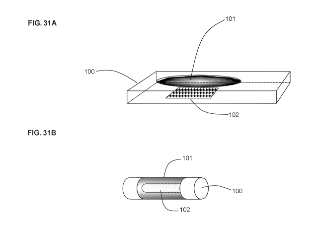
FIG. 31A is a drawing of a non-limiting example of an implantable glucose
sensor of the invention. As
illustrated in this figure, enclosure (100) includes a semipermeable
biointerface film (101), and working
electrode (102) is disposed internally within enclosure (100). In this
configuration, working electrode
(102) can be a metal foil (e.g., a silver foil) or a metallized plastic
surface. The drawing is not to scale.
FIG. 31B is a drawing of another non-limiting example of an implantable
glucose sensor of the invention.
As illustrated in this figure, enclosure (100) includes a semipermeable
biointerface film (101), and working
electrode (102) is disposed internally within enclosure (100). In this
configuration, working electrode
(102) can be a wire (e.g., a gold wire) or a metallized plastic thread. The
drawing is not to scale.
FIG. 32A is a drawing explicating the relative spatial relationship between
monolayer semipermeable
biointerface film layer (101), working electrode layer (102), and glucose-
oxidizing enzyme layer (103). In
this arrangement, layer (101) is externally facing and layer (102) is
contained within an enclosure. Layer
(101) includes a biostabilizing additive. The drawing is not to scale.
FIG. 32B is a drawing explicating the relative spatial relationship between
bilayer semipermeable
biointerface film (101), working electrode layer (102), and glucose-oxidizing
enzyme layer (103). Film
(101) includes a semipermeable membrane layer (104) and a coating layer (105).
In this arrangement,
layer (105) is externally facing and layer (102) is contained within an
enclosure. Coating layer (105)
includes a biostabilizing additive. Membrane layer (104) may also include a
biostabilizing additive. The
drawing is not to scale.
FIG. 33 is a chart comparing protein adhesion on rods prepared with and
without a biostabilizing additive.
Number of samples = 2. The values along the Y axis correspond to the BCA
adhesion values normalized
to the reference rod.
11
CA 03063377 2019-11-04
WO 2017/195035
PCT/IB2017/000636
FIG. 34 is a chart comparing thrombosis observed on rods prepared with and
without a biostabilizing
additive. Number of samples = 21.
Detailed Description
The invention features a biostable semipermeable biointerface film for use in
implantable glucose
sensors. Thus, the invention provides an implantable glucose sensor including
a glucose detector and an
enclosure defining a boundary between an internal space and an external space.
The glucose detector is
disposed in the internal space. The enclosure includes a semipermeable
biointerface film containing a
base polymer and a biostabilizing additive, where the semipermeable
biointerface film has a biostable
surface and is permeable to glucose and, optionally, oxygen. The biostable
surface faces the external
space or both the internal space and the external space.
The implantable glucose sensor of the invention is configured to include the
semipermeable biointerface
film between a tissue of a subject and the glucose detector, and the glucose
detector does not contact a
tissue of a subject upon implantation of the implantable glucose sensor into
the subject. The implantable
glucose sensor of the invention is configured to place the biostable surface
in contact with a tissue of a
subject upon implantation of the implantable glucose sensor into the subject.
The implantable glucose sensor of the invention may be a subcutaneous,
intravascular (e.g.,
intravenous), or transcutaneous glucose sensor.
Advantageously, the implantable glucose sensors of the invention may have a
prolonged in vivo lifespan
(e.g., at least 5%, at least 10%, at least 20%, or at least 50% longer
lifespan) in comparison to a
reference implantable glucose sensor that differs from the glucose sensor of
the invention only by the
absence of the biostabilizing additive in the reference glucose sensor.
The implantable glucose sensors of the invention may also exhibit a reduced
mean absolute relative
difference (MARD) in comparison to a reference implantable glucose sensor that
differs from the glucose
sensor of the invention only by the absence of the biostabilizing additive in
the reference glucose sensor.
Typically, the implantable glucose sensors of the invention may exhibit an
initial MARD of less than 13%
(e.g., less than 12%, less than 11%, less than 10%, less than 9%, less than
8%, less than 7%, or less
than 6%). In some embodiments, the implantable glucose sensor of the invention
exhibits an initial
MARD of less than 9%. Typically, the implantable glucose sensors of the
invention may exhibit an initial
MARD of e.g., more than 0.1% (e.g., more than 1%, more than 2%, more than 3%,
more than 4%, more
than 5%, or more than 6%).
Further, the biostable surface of the semipermeable biointerface film in the
glucose sensors of the
invention may exhibit reduced protein and cell deposition as compared to a
reference film that differs from
the semipermeable biointerface film in the glucose sensors of the invention
only by the absence of the
biostabilizing additive in the reference film. The protein and cell deposition
may be measured using
12
CA 03063377 2019-11-04
WO 2017/195035
PCT/IB2017/000636
methods known in the art. For example, protein deposition may be measured
using bicinchoninic acid
assay, e.g., as described herein. Cell deposition may be measured by comparing
SEM imaged of the
surfaces of explanted semipermeable biointerface films that were previously
implanted in an animal
model.
The biostable surface of the semipermeable biointerface film in the glucose
sensors of the invention may
exhibit a substantially similar aqueous wettability, as compared to a
reference film that differs from the
semipermeable biointerface film in the glucose sensors of the invention only
by the absence of the
biostabilizing additive in the reference film. Typically, aqueous wettability
is measured by the diameter of
a wet circle produced by placing a predetermined quantity of water as a single
drop on a semipermeable
biointerface film of a predetermined thickness.
The biostable surface of the semipermeable biointerface film of the invention
may exhibit a substantially
similar hydration, as compared to a reference surface of a reference membrane
that differs from the
semipermeable biointerface membrane of the invention only by the absence of a
biostabilizing additive.
The hydration of a semipermeable biointerface film may be measured as a
percentage increase in the
mass of a semipermeable biointerface film of a predetermined size after its
immersion in water for a
predetermined period of time. Typically hydration of the biointerface film of
the invention may be at least
about 5% (w/w) (e.g., at least about 10% (w/w), at least about 20% (w/w), at
least about 50% (w/w), at
least about 100% (w/w), at least about 300% (w/w) (e.g., from about 10% (w/w)
to about 1000% (w/w),
from about 50% (w/w) to about 1000% (w/w), from about 100% (w/w) to about
1000% (w/w), from about
10% (w/w) to about 500% (w/w), from about 50% (w/w) to about 500% (w/w), or
from about 100% (w/w)
to about 500% (w/w)).
The biostable surface of the semipermeable biointerface membrane of the
invention may exhibit a
reduction in the inflammatory response in a tissue that is in contact with the
biostable surface, as
compared to a reference surface of a reference membrane that differs from the
semipermeable
biointerface membrane of the invention only by the absence of a biostabilizing
additive.
Without wishing to be bound by a theory, the inclusion of the biostabilizing
additives in the semipermeable
biointerface films of the invention may reduce protein and cellular attachment
to the semipermeable
biointerface films and may reduce the rate of barrier cell layer (e.g.,
fibrotic capsule) formation, thereby
enhancing the overall lifetime of the device without compromising the glucose
permeability of the
biointerface films.
The semipermeable biointerface membrane of the invention may exhibit a reduced
permeability (e.g., by
at least about 5%, by at least about 10%, by at least about 20%, by at least
about 50%, or by at least
about 70% (e.g., by from about 5% to about 80%, by from about 10% to about
80%, by from about 20%
to about 80%, or by from about 50% to about 80%)) for certain electrochemical
interferents (e.g.,
acetaminophen), as compared to a reference semipermeable biointerface membrane
that differs from the
semipermeable biointerface membrane of the invention only by the absence of a
biostabilizing additive.
13
CA 03063377 2019-11-04
WO 2017/195035
PCT/IB2017/000636
Typical electrochemical interferents known in the art include acetaminophen,
salicylic acid, tetracycline,
dopamine, ephedrine, ibuprofen, L-DOPA, methyl-DOPA, tolazamide, ascorbic
acid, bilirubin, cholesterol,
creatinine, triglycerides, and uric acid.
Glucose Detection Approaches
Electrochemical Glucose Detection
Implantable glucose sensors of the invention may be implantable
electrochemical glucose sensors which
detect glucose in a subject using enzymatic or non-enzymatic approaches known
in the art.
An enzymatic approach typically involves a glucose-oxidizing enzyme-mediated
(e.g., glucose oxidase-
mediated) oxidation reaction between glucose and an oxidizer (e.g., oxygen) to
give gluconolactone and
a reduced form of the oxidizer (e.g., hydrogen peroxide). In these approaches,
a working electrode of the
glucose sensor typically detects an amperometric signal obtained by
electrochemical oxidation of the
reduced mediator (e.g., electrochemical oxidation of hydrogen peroxide to
oxygen). In some enzymatic
approaches, the oxidation reaction is a glucose-oxidizing enzyme-mediated
(e.g., glucose oxidase-
mediated) electrochemical oxidation of glucose to gluconolactone, where the
role of an oxidizer is
performed by a working electrode linked to the enzyme. In these approaches, a
working electrode of the
glucose sensor typically detects an amperometric signal obtained by a glucose-
oxidizing enzyme-
mediated (e.g., glucose oxidase-mediated) electrochemical oxidation of glucose
to gluconolactone. Other
non-limiting examples of the enzymes that may be used in the enzymatic
approaches include glucose
dehydrogenases and quinoprotein-based glucose dehydrogenases.
The implantable electrochemical glucose sensors of the invention relying on
the enzymatic (e.g., glucose
oxidase-mediated) glucose detection approach typically further include a
glucose oxidase layer disposed
between the working electrode and the semipermeable biointerface film. The
working electrodes used in
implantable electrochemical glucose sensors utilizing enzymatic approach to
glucose detection may be
those known in the art as being useful in the field of implantable
electrochemical glucose sensors.
A non-enzymatic approach to glucose detection typically involves detecting an
amperometric signal
obtained by direct electrochemical oxidation of glucose to gluconolactone. A
working electrode utilized in
these approaches is typically a nanostructured electrode having a high surface
area and electrocatalytic
activity. Nanostructure electrodes that may be used in the implantable
electrochemical glucose sensors
are known in the art (e.g., platinum nanoforests, platinum-lead alloy
nanowires, gold nanoparticles, or
alloy nanostructures (e.g., containing platinum, lead, gold, palladium, and/or
rhodium)).
Desirably, the implantable electrochemical glucose sensors of the invention
produce a linear response to
glucose levels up to at least about 400 mg/dL.
The implantable electrochemical glucose sensors of the invention may be used
with data retrievers and
processors known in the art for processing amperometric signals produced by
implantable glucose
14
CA 03063377 2019-11-04
WO 2017/195035
PCT/IB2017/000636
sensors. For example, such data retrievers and processors are described in
U.S. Patent Nos. 8,844,057
and 8,251,906.
Optical Glucose Detection
Implantable glucose sensors of the invention may be implantable optical
glucose sensors which utilize a
glucose recognition element for the detection of glucose. Typically, a glucose
recognition element
includes a glucose-binding fluorophore. Non-limiting examples of the glucose-
binding fluorophores and
glucose recognition elements that may be used in the implantable optical
glucose sensors of the invention
are described in US 2014/0088383.
Electrode Systems
The implantable electrochemical glucose sensors of the invention include an
electrode system capable of
producing an amperometric signal allowing for the detection of glucose levels.
The electrode systems
used in the implantable electrochemical glucose sensors of the invention may
be those known in the art.
Typical electrode systems include a working electrode (anode), a counter-
electrode (cathode), and a
reference electrode. Various configurations of electrode systems are known in
the art. A non-limiting
example of an electrode system configuration is described in US 2005/0245799.
Typically, the working
electrode and the counter-electrode of a glucose oxidase-based implantable
electrochemical glucose
sensor require access to intracorporeal oxygen. Accordingly, in these
embodiments, the implantable
electrochemical glucose sensor includes a counter-electrode that is configured
to be in oxygen
communication with the external space through a semipermeable biointerface
film. In some
embodiments of the three-electrode system, all three electrodes are configured
to be in glucose and
oxygen communication with the external space through a semipermeable
biointerface film.
Glucose-oxidizing Enzyme Layer
The implantable electrochemical glucose sensors of the invention may include a
glucose-oxidizing
enzyme layer (e.g., a glucose oxidase layer) between the semipermeable
biointerface film and a working
electrode. The glucose-oxidizing enzyme layer typically contains an effective
amount of a glucose-
oxidizing enzyme (e.g., glucose oxidase enzyme, a glucose dehydrogenase, or a
quinoprotein-based
glucose dehydrogenase). The glucose-oxidizing enzyme layer may be formulated
as a polymer matrix
including an effective amount of a glucose-oxidizing enzyme and an oxygen-
solubilizing polymer (e.g., a
silicone, fluorocarbon polymer, perfluorocarbon polymer, or perfluoroether
polymer). In addition, the
polymer matrix may include an additive (e.g., polyethylene glycol, propylene
glycol, pyrrolidone, an ester,
an amide, or a carbonate). The thickness of the glucose-oxidizing enzyme layer
may be from about 0.5
micron (e.g., from about 1 micron) to about 40, 50, 60, 70, 80, 90, or 100
microns. For example, the
thickness of the glucose-oxidizing enzyme layer may be between about 1, 2, 3,
4, or 5 microns and 13,
14, 15, 20, 25, or 30 microns. The principles that may be utilized for
including a glucose-oxidizing
enzyme layer in implantable electrochemical glucose sensors of the invention
are known in the art. For
example, such principles are described in U.S. Patent No. 8,255,030.
15
CA 03063377 2019-11-04
WO 2017/195035
PCT/IB2017/000636
Glucose-flux Control Layer
The implantable electrochemical glucose sensors of the invention may further
include a glucose-flux
control layer disposed between the semipermeable biointerface film and the
glucose-oxidizing enzyme
layer. The glucose-flux control layers are known in the art. See, e.g., U.S.
Patent No. 8,744,546. The
glucose-flux control layer may be used to control the flux of glucose across
the semipermeable
biointerface films to reduce the amount of glucose that passes through to the
glucose-oxidizing enzyme
layer. Desirably, the glucose-flux control is achieved without compromising a
linear response of the
implantable electrochemical glucose sensors of the invention to glucose up to
at least about 400 mg/dL.
The inclusion of glucose-flux control layer may be beneficial in the glucose
sensors exhibiting insufficient
control over glucose flux across the semipermeable biointerface films, which
may result in oxygen
insufficiency at high glucose concentrations, thereby producing non-linear
response at higher glucose
levels.
Alternatively, the semipermeable biointerface films of the invention may
enhance oxygen flux across the
film and/or reduce the flux of glucose, thereby reducing or even negating the
need for glucose-flux control
layers. Accordingly, some of the implantable electrochemical glucose sensors
may be free of glucose-
flux control layers.
Semipermeable Biointerface Films
Semipermeable biointerface films of the invention contain a biostabilizing
additive and a base polymer
(e.g., the biostabilizing additive is from 0.05% (w/w) to 15% (w/w) (e.g.,
from 0.05% (w/w) to 10% (w/w))
relative to the total mass of the semipermeable biointerface film).
Semipermeable biointerface films are
monolayer or bilayer films, where one of the layers is a semipermeable
membrane containing a base
polymer (e.g., a thermoplastic). In a bilayer film, the second layer may be a
coating on the
semipermeable membrane. Typically, the biostabilizing additives used in the
semipermeable biointerface
films of the invention may leave bulk properties of the base polymer material
substantially unchanged.
Typically, a semipermeable biointerface film of the invention may have a
thickness of from 1 to 200
microns (e.g., from 1 to 150 microns, from 1 to 100 microns, from 1 to 50
microns, from 5 to 150 microns,
from 5 to 100 microns, from 5 to 50 microns, from 10 to 150 microns, from 10
to 100 microns, from 10 to
50 microns, from 1 to 20 microns, from 20 to 50 microns, from 50 to 100
microns, from 100 to 150
microns, or from 150 to 200 microns).
Semipermeable biointerface films of the invention may further include a
biologically active agent. The
biologically active agent may, for example, be included in the coating used in
the bilayer semipermeable
biointerface films of the invention. The bioactive agents incorporated in the
semipermeable biointerface
films of the invention may further enhance biostability of the tissue-
contacting surface of the
semipermeable biointerface film.
16
CA 03063377 2019-11-04
WO 2017/195035
PCT/IB2017/000636
Base Polymers
The base polymer of the semipermeable membrane may be is a silicone,
polyolefin, polyester,
polycarbonate, polysulfone, polyamide, polyether, polyurea, polyurethane,
polyetherimide, or cellulosic
polymer, or a copolymer thereof or a blend thereof (e.g., a silicone,
polycarbonate, polypropylene (PP),
polyvinylchloride (PVC), polyvinyl alcohol (PVA), polyvinylpyrrolidone (PVP),
polyacrylamide (PAAM),
polyethylene oxide, poly(ethylene oxide)-b-poly(propylene oxide)-b-
poly(ethylene oxide),
poly(hydroxyethylmethacrylate) (polyHEMA), polyethylene terephthalate (PET),
polybutylene
terephthalate (PBT), polymethylmethacrylate (PMMA), polyether ether ketone
(PEEK), polyamide,
polyurethane, cellulosic polymer, polysulfone, or a copolymer thereof or a
blend thereof). A base polymer
used in the semipermeable biointerface films of the invention may be, e.g.,
polyvinylpyrrolidone (PVP),
polyacrylamide (PAAM), polyethylene oxide, poly(ethylene oxide)-b-
poly(propylene oxide)-b-poly(ethylene
oxide), poly(hydroxyethylmethacrylate) (polyHEMA), polyether-b-polyamide
(e.g., PEBAX), or
polyurethane. A base polymer used in the semipermeable biointerface films of
the invention may be a
thermoplastic polymer (e.g., a thermoplastic polyurethane). The base polymers
of the semipermeable
membrane may also be cross-linked.
Biostabilizing Additives
The biostabilizing additives used in the implantable glucose sensors of the
invention may be described by
the structure of any one of formulae (I), (II), (III), (IV), (V), (VI), (VII),
(VIII), (IX), (X), (XI), (XII), (XIII), (XIV),
(XV), (XVI), and (XVII) shown below.
(1) Formula (I):
FT¨[B¨A]n¨B¨FT
(I)
where
(i) A includes hydrogenated polybutadiene, poly((2,2-dimethyl)-1,3-
propylene carbonate),
polybutadiene, poly(diethylene glycol)adipate, poly(hexamethylene carbonate),
poly(ethylene-co-butylene), (neopentyl glycol-ortho phthalic anhydride)
polyester,
(diethylene glycol-ortho phthalic anhydride) polyester, (1,6-hexanediol-ortho
phthalic
anhydride) polyester, or bisphenol A ethoxylate;
(ii) B is a segment including a urethane; and
(iii) FT is a polyfluoroorgano group, and
(iv) n is an integer from 1 to 10.
(2) Formula (II):
FT¨[B¨A]n¨B¨FT
(II)
where
(i) B includes a urethane;
(ii) A includes polypropylene oxide, polyethylene oxide, or
polytetramethylene oxide;
(iii) FT is a polyfluoroorgano group; and
17
CA 03063377 2019-11-04
WO 2017/195035
PCT/IB2017/000636
(iv) n is an integer from 1 to 10.
(3) Formula (III) or Formula (IV):
FTµ FT
,FT FTµ ,FT
B¨A1B¨A)¨B B¨A¨(13¨A)-13,
FT T
1 n µFT, F/ n FT
(III) (IV)
where
(i) A is an oligomeric segment containing an ether linkage, an ester
linkage, a carbonate
linkage, or a polyalkylene and having a theoretical molecular weight of from
500 to 3,500
Daltons (e.g., from 500 to 2,000 Daltons, from 1,000 to 2,000 Daltons, or from
1,000 to
3,000 Daltons);
(ii) B is a segment including a isocyanurate trimer or biuret trimer; B',
when present, is a
segment including a urethane;
(iii) each FT is a polyfluoroorgano group; and
(iv) n is an integer between 0 to 10.
(4) Formula (V):
FT¨[B¨A]n¨B¨FT
(V)
where
(i) A is an oligomeric segment including polypropylene oxide, polyethylene
oxide, or
polytetramethylene oxide and having a theoretical molecular weight of from 500
to 3,000
Daltons (e.g., from 500 to 2,000 Daltons, from 1,000 to 2,000 Daltons, or from
1,000 to
3,000 Daltons);
(ii) B is a segment formed from a diisocyanate;
(iii) FT is a polyfluoroorgano group; and
(iv) n is an integer from 1 to 10.
(5) Formula (VI):
FTµ FT
/1 iFT
B¨A1B¨A)-13,
FT n FT
(VI)
where
(i) A is an oligomeric segment including polyethylene oxide, polypropylene
oxide,
polytetramethylene oxide, or a mixture thereof, and having a theoretical
molecular weight
of from 500 to 3,000 Daltons (e.g., from 500 to 2,000 Daltons, from 1,000 to
2,000
Daltons, or from 1,000 to 3,000 Daltons);
(ii) B is a segment including an isocyanurate trimer or biuret trimer;
(iii) FT is a polyfluoroorgano group; and
(iv) n is an integer from 0 to 10.
18
CA 03063377 2019-11-04
WO 2017/195035
PCT/IB2017/000636
(6) Formula (VII):
FT¨[B¨A]n¨B¨FT
(VII)
where
(i) A is a polycarbonate polyol having a theoretical molecular
weight of from 500 to 3,000
Daltons (e.g., from 500 to 2,000 Daltons, from 1,000 to 2,000 Daltons, or from
1,000 to
3,000 Daltons);
(ii) B is a segment formed from a diisocyanate;
(iii) FT is a polyfluoroorgano group; and
(iv) n is an integer from 1 to 10.
(7) Formula (VIII):
FTµ 11T
/FT
B¨A1 )
B¨A13 ¨,
FT/ n FT
(VIII)
where
(i) A is an oligomeric segment including a polycarbonate polyol
having a theoretical
molecular weight of from 500 to 3,000 Daltons (e.g., from 500 to 2,000
Daltons, from
1,000 to 2,000 Daltons, or from 1,000 to 3,000 Daltons);
(ii) B is a segment including an isocyanurate trimer or biuret trimer;
(iii) FT is a polyfluoroorgano group; and
(iv) n is an integer from 0 to 10.
(8) Formula (IX):
FTµ 1T ,FT
B¨A¨(B¨A)13 ¨,
FT/ n FT
(IX)
where
(i) A includes a first block segment selected from polypropylene oxide,
polyethylene oxide,
polytetramethylene oxide, or a mixture thereof, and a second block segment
including a
polysiloxane or polydimethylsiloxane, where A has a theoretical molecular
weight of from
1,000 to 5,000 Daltons (e.g., from 1,000 to 3,000 Daltons, from 2,000 to 5,000
Daltons, or
from 2,500 to 5,000 Daltons);
(ii) B is a segment including an isocyanurate trimer or biuret trimer;
(iii) FT is a polyfluoroorgano group; and
(iv) n is an integer from 0 to 10.
(9) Formula (X):
FT¨[B¨A]n¨B¨FT
19
CA 03063377 2019-11-04
WO 2017/195035
PCT/IB2017/000636
(X)
where
(i) A is a segment selected from the group consisting of
hydrogenated polybutadiene (e.g.,
HLBH), polybutadiene (e.g., LBHP), hydrogenated polyisoprene (e.g., HHTPI),
polysiloxane-polyethylene glycol block copolymer, and polystyrene and has a
theoretical
molecular weight of from 750 to 3,500 Daltons (e.g., from 750 to 2,000
Daltons, from
1,000 to 2,500 Daltons, or from 1,000 to 3,500 Daltons);
(ii) B is a segment formed from a diisocyanate;
(iii) FT is a polyfluoroorgano group; and
(iv) n is an integer from 1 to 10.
(10) Formula (XI):
FTµ FT
/FT
B¨A1/B¨A)-13,
FT/ n FT
(XI)
where
(i) A is hydrogenated polybutadiene (e.g., HLBH), polybutadiene
(e.g., LBHP),
hydrogenated polyisoprene (e.g., HHTPI), or polystyrene and has a theoretical
molecular
weight of from 750 to 3,500 Daltons (e.g., from 750 to 2,000 Daltons, from
1,000 to 2,500
Daltons, or from 1,000 to 3,500 Daltons);
(ii) B is a segment including an isocyanurate trimer or biuret trimer;
(iii) FT is a polyfluoroorgano group; and
(iv) n is an integer from 0 to 10.
(11) Formula (XII):
FTµ 1T ,FT
B¨A¨(B¨A)13 ¨,
FT/ n FT
(XI I)
where
(i) A is a polyester having a theoretical molecular weight of from
500 to 3,500 Daltons (e.g.,
from 500 to 2,000 Daltons, from 1,000 to 2,000 Daltons, or from 1,000 to 3,000
Daltons);
(ii) B is a segment including an isocyanurate trimer or biuret trimer;
(iii) FT is a polyfluoroorgano group; and
(iv) n is an integer from 0 to 10.
(12) Formula (XIII):
FT¨A¨FT
(XIII)
where FT is a polyfluoroorgano group and A is an oligomeric segment.
CA 03063377 2019-11-04
WO 2017/195035
PCT/IB2017/000636
(13) Formula (XIV):
(F1)
C-A-[(LinkB)-A]a-C
(XIV)
where
(i) FT is a polyfluoroorgano group covalently attached to LinkB;
(ii) C is a chain terminating group;
(iii) A is an oligomeric segment;
(iv) LinkB is a coupling segment; and
(v) a is an integer greater than 0.
(14) Formula (XV):
/ FT L1 0 ____________________________ X1
0
)......../..-^... ...."..,.....õ--0,,,
0 A2
n
X3 ¨L2-0 ____________________________
(XV)
where
(i) each FT is independently a surface-active group selected from
polydimethylsiloxanes,
hydrocarbons, and polyfluoroorgano groups, and combinations thereof (e.g.,
each FT is
independently a polyfluoroorgano);
(ii) X, is H, CH3, or CH2CH3;
(iii) each of X2 and X3 is independently H, CH3, CH2CH3, or FT;
(iv) each of Li and L2 is independently a bond, an oligomeric linker, or a
linker with two
terminal carbonyls; and
(v) n is an integer from 5 to 50.
(15) Formula (XVI):
FT¨L1 y-0 0-...õ..00-.......
Xi
n1
X3¨L2 ¨O ______________________________ 0-.....õõ..----,. õ.-",-...,.....,-0-
-......X2 0
n2
(XVI)
where
(i) each FT is independently a surface-active group (e.g., a
polyfluoroorgano);
(ii) each of Xi, X2, and X3 is independently H, CH3, 0H20H3, or FT;
(iii) each of Li and L2 is independently a bond, an oligomeric linker, a
linker with two terminal
carbonyls, or is formed from a diisocyanate; and
(iv) each of n1 and n2 is independently an integer from 5 to 50.
21
CA 03063377 2019-11-04
WO 2017/195035
PCT/IB2017/000636
(16) Formula (XVII):
G ¨ Am ¨ [B ¨ A]n ¨ B ¨ G
(XVII)
where
(i) each A includes hydrogenated polybutadiene, poly ((2,2-dimethyl)-1,3-
propylene
carbonate), polybutadiene, poly (diethylene glycol)adipate, poly
(hexamethylene
carbonate), poly (ethylene-co-butylene), (diethylene glycol-ortho phthalic
anhydride)
polyester, (1,6-hexanediol-ortho phthalic anhydride) polyester, (neopentyl
glycol-ortho
phthalic anhydride) polyester, a polysiloxane, or bisphenol A ethoxylate;
(ii) each B is independently a bond, an oligomeric linker, or a linker with
two terminal
carbonyls;
(iii) each G is H or a polyfluoroograno, provided that at least one G is a
polyfluoroorgano;
(iv) n is an integer from 1 to 10; and
(v) m is 0 or 1.
The biostabilizing additive of formula (I) or formula (II) can include B
formed from a diisocyanate (e.g., 3-
isocyanatomethy1-3,5,5-trimethyl-cyclohexylisocyanate; 4,4'-methylene
bis(cyclohexyl isocyanate); 4,4'-
methylene bis(phenyl isocyanate); toluene-2,4-diisocyanate; m-
tetramethylxylene diisocyanate; or
hexamethylene diisocyanate). The variable n may be 1 or 2. The implantable
glucose sensors of the
invention may include a semipermeable biointerface film (e.g., a monolayer or
a bilayer film) containing a
base polymer and the biostabilizing additive of formula (I) or formula (II).
The biostabilizing additive of formulae (III) and (IV) can include A that is
an oligomeric segment containing
hydrogenated polybutadiene (HLBH), poly((2,2-dimethyl)-1,3-propylene
carbonate) (PCN), polybutadiene
(LBHP), polytetramethylene oxide (PTMO), polypropylene oxide (PPO),
(diethyleneglycol-orthophthalic
anhydride) polyester (PDP), hydrogenated polyisoprene (HHTPI),
poly(hexamethylene carbonate),
poly((2-butyl-2-ethyl)-1,3-propylene carbonate), or hydroxylterminated
polydimethylsiloxane (022). In the
biostabilizing additive of formulae (III) and (IV), B is formed by reacting a
triisocyanate (e.g.,
hexamethylene diisocyanate (HDI) biuret trimer, isophorone diisocyanate (IPDI)
trimer, or hexamethylene
diisocyanate (H DI) trimer) with a diol including the oligomeric segment A.
The implantable glucose
sensors of the invention may include a semipermeable biointerface film (e.g.,
a monolayer or a bilayer
film) containing a base polymer and the biostabilizing additive of formula
(III). The implantable glucose
sensors of the invention may include a semipermeable biointerface film (e.g.,
a monolayer or a bilayer
film) containing a base polymer and the biostabilizing additive of formula
(IV).
In the biostabilizing additive of formula (V), B may be a segment formed from
3-isocyanatomethy1-3,5,5-
trimethyl-cyclohexylisocyanate; 4,4'-methylene bis(cyclohexyl isocyanate);
4,4'-methylene bis(phenyl
isocyanate); toluene-2,4-diisocyanate; m-tetramethylxylene diisocyanate; and
hexamethylene
diisocyanate. In the biostabilizing additive of formula (V), segment A can be
poly(ethylene oxide)-b-
poly(propylene oxide)-b-poly(ethylene oxide). The variable n may be an integer
from 1 to 3. The
22
CA 03063377 2019-11-04
WO 2017/195035
PCT/IB2017/000636
implantable glucose sensors of the invention may include a semipermeable
biointerface film (e.g., a
monolayer or a bilayer film) containing a base polymer and the biostabilizing
additive of formula (V).
In the biostabilizing additive of formula (VI), B is a segment formed by
reacting a triisocyanate with a diol
of A. The triisocyanate may be hexamethylene diisocyanate (HDI) biuret trimer,
isophorone diisocyanate
(IPDI) trimer, or hexamethylene diisocyanate (HDI) trimer. In the
biostabilizing additive of formula (VI),
segment A can be poly(ethylene oxide)-b-poly(propylene oxide)-b-poly(ethylene
oxide). The variable n
may be 0, 1, 2, or 3. The implantable glucose sensors of the invention may
include a semipermeable
biointerface film (e.g., a monolayer or a bilayer film) containing a base
polymer and the biostabilizing
additive of formula (VI).
In the biostabilizing additive of formula (VII), Oligo can include poly((2,2-
dimethyl)-1,3-propylene
carbonate) (PCN). B may be a segment formed from 3-isocyanatomethy1-3,5,5-
trimethyl-
cyclohexylisocyanate; 4,4'-methylene bis(cyclohexyl isocyanate); 4,4'-
methylene bis(phenyl isocyanate);
toluene-2,4-diisocyanate; m-tetramethylxylene diisocyanate; and hexamethylene
diisocyanate. The
variable n may be 1, 2, or 3. The implantable glucose sensors of the invention
may include a
semipermeable biointerface film (e.g., a monolayer or a bilayer film)
containing a base polymer and the
biostabilizing additive of formula (VII).
In the biostabilizing additive of formula (VIII), B is a segment formed by
reacting a triisocyanate with a diol
of A (e.g., the oligomeric segment). The triisocyanate may be hexamethylene
diisocyanate (HDI) biuret
trimer, isophorone diisocyanate (IPDI) trimer, or hexamethylene diisocyanate
(HDI) trimer. The segment
A can include poly((2,2-dimethyl)-1,3-propylene carbonate) (PCN) or
poly(hexamethylene carbonate)
(PHCN). The variable n may be 0, 1, 2, or 3. The implantable glucose sensors
of the invention may
include a semipermeable biointerface film (e.g., a monolayer or a bilayer
film) containing a base polymer
and the biostabilizing additive of formula (VIII).
In the biostabilizing additive of formula (IX), B is a segment formed by
reacting a triisocyanate with a diol
of A. In segment A, the number of first block segments and second block
segments can be any integer or
non-integer to provide the approximate theoretical molecule weight of the
segment. The segment A can
include polypropylene oxide and polydimethylsiloxane. The triisocyanate may be
hexamethylene
diisocyanate (HDI) biuret trimer, isophorone diisocyanate (IPDI) trimer, or
hexamethylene diisocyanate
(HDI) trimer. The variable n may be 0, 1, 2, or 3. The implantable glucose
sensors of the invention may
include a semipermeable biointerface film (e.g., a monolayer or a bilayer
film) containing a base polymer
and the biostabilizing additive of formula (IX).
In biostabilizing additive of formula (X), B is a segment formed from a
diisocyanate. The segment A can
include hydrogenated polybutadiene. Alternatively, the segment A can include
polysiloxane-polyethylene
glycol block copolymer (e.g., PEG-PDMS-PEG). The segment B may be formed from
3-
isocyanatomethy1-3,5,5-trimethy-cyclohexylisocyanate; 4,4'-methylene
bis(cyclohexyl isocyanate); 4,4'-
methylene bis(phenyl isocyanate); toluene-2,4-diisocyanate; m-
tetramethylxylene diisocyanate; and
23
CA 03063377 2019-11-04
WO 2017/195035
PCT/IB2017/000636
hexamethylene diisocyanate. The variable n may be 1, 2, or 3. The implantable
glucose sensors of the
invention may include a semipermeable biointerface film (e.g., a monolayer or
a bilayer film) containing a
base polymer and the biostabilizing additive of formula (X).
In the biostabilizing additive of formula (XI), B is a segment formed by
reacting a triisocyanate with a diol
of A. The segment A may be hydrogenated polybutadiene (HLBH) or hydrogenated
polyisoprene
(HHTPI). The triisocyanate may be hexamethylene diisocyanate (HDI) biuret
trimer, isophorone
diisocyanate (IPDI) trimer, or hexamethylene diisocyanate (HDI) trimer. The
variable n may be 0, 1, 2, or
3. The implantable glucose sensors of the invention may include a
semipermeable biointerface film (e.g.,
a monolayer or a bilayer film) containing a base polymer and the
biostabilizing additive of formula (XI).
In the biostabilizing additive of formula (XII), B is a segment formed by
reacting a triisocyanate with a diol
of A (e.g., polyester). The segment A may be poly(diethylene glycol)adipate,
(neopentyl glycol-ortho
phthalic anhydride) polyester, (diethylene glycol-ortho phthalic) anhydride
polyester, or (1,6-hexanediol-
ortho phthalic anhydride) polyester. The triisocyanate may be hexamethylene
diisocyanate (HDI) biuret
trimer, isophorone diisocyanate (IPDI) trimer, and hexamethylene diisocyanate
(HDI) trimer. The variable
n may be 0, 1, 2, or 3. The implantable glucose sensors of the invention may
include a semipermeable
biointerface film (e.g., a monolayer or a bilayer film) containing a base
polymer and the biostabilizing
additive of formula (XII).
The biostabilizing additive of formula (XIII) can include a segment A that is
a branched or non-branched
oligomeric segment of fewer than 20 repeating units (e.g., from 2 to 15 units,
from 2 to 10 units, from 3 to
15 units, and from 3 to 10 units). In certain embodiments, the biostabilizing
additive of formula (XIII)
include an oligomeric segment selected from polyurethane, polyurea, polyamide,
polyalkylene oxide,
polycarbonate, polyester, polylactone, polysilicone, polyethersulfone,
polyolefin, polyvinyl derivative,
polypeptide, polysaccharide, polysiloxane, polydimethylsiloxane, polyethylene-
butylene, polyisobutylene,
polybutadiene, polypropylene oxide, polyethylene oxide, polytetramethylene
oxide, or
polyethylenebutylene segments. The implantable glucose sensors of the
invention may include a
semipermeable biointerface film (e.g., a monolayer or a bilayer film)
containing a base polymer and the
biostabilizing additive of formula (XIII).
The biostabilizing additive of formula (XIV) can include a segment A that is a
branched or non-branched
oligomeric segment of fewer than 20 repeating units (e.g., from 2 to 15 units,
from 2 to 10 units, from 3 to
15 units, and from 3 to 10 units). In certain embodiments, the biostabilizing
additive of formula (XIV)
include an oligomeric segment selected from polyurethane, polyurea, polyamide,
polyalkylene oxide,
polycarbonate, polyester, polylactone, polysilicone, polyethersulfone,
polyolefin, polyvinyl derivative,
polypeptide, polysaccharide, polysiloxane, polydimethylsiloxane, polyethylene-
butylene, polyisobutylene,
polybutadiene, polypropylene oxide, polyethylene oxide, or polytetramethylene
oxide. The implantable
glucose sensors of the invention may include a semipermeable biointerface film
(e.g., a monolayer or a
bilayer film) containing a base polymer and the biostabilizing additive of
formula (XIV).
24
CA 03063377 2019-11-04
WO 2017/195035
PCT/IB2017/000636
The biostabilizing additive of formula (XV) can include a segment Li that is
an oligomeric linker (e.g., of
fewer than 50 repeating units (e.g., from 2 to 40 units, from 2 to 30 units,
from 3 to 20 units, or from 3 to
units)). In some embodiments of formula (XV), L2 is an oligomeric linker
(e.g., of fewer than 50
repeating units (e.g., from 2 to 40 units, from 2 to 30 units, from 3 to 20
units, or from 3 to 10 units)). In
5 particular embodiments of formula (XV), each of Li and L2 is a bond. In
certain embodiments of formula
(XV), the biostabilizing additive includes an oligomeric segment (e.g., in any
one of Li and L2) selected
from the group consisting of polyurethane, polyurea, polyamide, polyalkylene
oxide (e.g., polypropylene
oxide, polyethylene oxide, or polytetramethylene oxide), polyester,
polylactone, polysilicone,
polyethersulfone, polyolefin, polyvinyl derivative, polypeptide,
polysaccharide, polysiloxane,
10 polydimethylsiloxane, poly(ethylene-co-butylene), polyisobutylene, and
polybutadiene. In some
embodiments of formula (XV), the biostabilizing additive is a compound of
formula (XV-A):
FT (0 )/ 0 X1
0
0 _____________________________________
X3 (0
im2
(XV-A),
where each of ml and m2 is independently an integer from 0 to 50. In
particular embodiments of formula
(XV-A), ml is 5, 6, 7, 8, 9, or 10 (e.g., ml is 6). In some embodiments of
formula (XV-A), m2 is 5, 6, 7, 8,
9, or 10 (e.g., m2 is 6).
In certain embodiments of formula (XV) or (XV-A), X2 is FT. In other
embodiments, X2 is CH3 or 0H20H3.
In particular embodiments of formula (XV) or (XV-A), X3 is FT. In other
embodiments, each FT is
independently a polyfluoroorgano (e.g., a polyfluoroacyl, such as ¨(0)q-
[C(=0)]r(CH2)0(CF2)pCF3, in
which q is 0, r is 1; o is from 0 to 2; and p is from 0 to 10). In certain
embodiments of formula (XV) or
(XV-A), n is an integer from 5 to 40 (e.g., from 5 to 20, such as from 5, 6,
7, 8, 9, or 10). In some
embodiments of formula (XV) or (XV-A), each FT includes (0F2)50F3. The
implantable glucose sensors of
the invention may include a semipermeable biointerf ace film (e.g., a
monolayer or a bilayer film)
containing a base polymer and the biostabilizing additive of formula (XV). The
implantable glucose
sensors of the invention may include a semipermeable biointerface film (e.g.,
a monolayer or a bilayer
film) containing a base polymer and the biostabilizing additive of formula (XV-
A).
The biostabilizing additive of formula (XVI) can include a segment Li that is
an oligomeric linker (e.g., of
fewer than 50 repeating units (e.g., from 2 to 40 units, from 2 to 30 units,
from 3 to 20 units, or from 3 to
10 units)). In some embodiments of formula (XVI), L2 is an oligomeric linker
(e.g., of fewer than 50
repeating units (e.g., from 2 to 40 units, from 2 to 30 units, from 3 to 20
units, or from 3 to 10 units)). In
particular embodiments of formula (XVI), each of Li and L2 is a bond. In
certain embodiments of formula
(XVI), the biostabilizing additive includes an oligomeric segment (e.g., in
any one of Li and L2) selected
from polyurethane, polyurea, polyamide, polyalkylene oxide (e.g.,
polypropylene oxide, polyethylene
oxide, or polytetramethylene oxide), polyester, polylactone, polysilicone,
polyethersulfone, polyolefin,
polyvinyl derivative, polypeptide, polysaccharide, polysiloxane,
polydimethylsiloxane, poly(ethylene-co-
CA 03063377 2019-11-04
WO 2017/195035
PCT/IB2017/000636
butylene), polyisobutylene, or polybutadiene. In some embodiments of formula
(XVI), the biostabilizing
additive is a compound of formula (XVI-A):
FT ( )
0-7'0
M' DC n1 X1
0
X3 (0 A2
n2
112
(XVI-A),
where each of ml and m2 is independently an integer from 0 to 50. In
particular embodiments of formula
(XV-A), ml is 5, 6, 7, 8, 9, or 10 (e.g., ml is 6). In some embodiments of
formula (XV-A), m2 is 5, 6, 7, 8,
9, or 10 (e.g., m2 is 6).
In certain embodiments of formula (XVI) or (XVI-A), X2 is FT. In other
embodiments of formula (XVI) or
(XVI-A), X2 is CH3 or 0H20H3. In particular embodiments of formula (XVI) or
(XVI-A), X3 is FT. In other
embodiments of formula (XVI) or (XVI-A), each FT is independently a
polyfluoroorgano (e.g., a
polyfluoroacyl, such as ¨(0)q-[C(=0)]r(CH2)0(CF2)pCF3, in which q is 0, r is
1; o is from 0 to 2; and p is
from 0 to 10). In some embodiments of formula (XVI) or (XVI-A), each FT
includes (0F2)50F3. The
implantable glucose sensors of the invention may include a semipermeable
biointerface film (e.g., a
monolayer or a bilayer film) containing a base polymer and the biostabilizing
additive of formula (XVI).
The implantable glucose sensors of the invention may include a semipermeable
biointerface film (e.g., a
monolayer or a bilayer film) containing a base polymer and the biostabilizing
additive of formula (XVI-A).
In some embodiments of formula (XVII), m is 1. The biostabilizing additive of
formula (XVII) can be a
.. compound of formula (XVI I-A):
G ¨ A ¨ [B ¨ A]n ¨ G
(XVI I-A).
In other embodiments of formula (XVII), m is 0. The biostabilizing additive of
formula (XVII) can be a
compound of formula (XVI I-B):
G ¨ [B ¨ A]n ¨ B ¨ G
(XVI I-B).
In particular embodiments of formula (XVII), (XVII-A), or (XVII-B), each B is
a linker with two terminal
carbonyls. In certain embodiments of formula (XVII), (XVII-A), or (XVII-B),
each B is a bond. In some
embodiments of Formula (XVII) , (XVII-A), or (XVII-B), the bond connecting G
and B is an oxycarbonyl
bond (e.g., an oxycarbonyl bond in an ester). In other embodiments of formula
(XVII), (XVII-A), or (XVII-
B), n is 1 or 2.
The biostabilizing additive of formula (XVII) can be a compound of formula
(XVII-C):
G ¨ A ¨ G
(XVII-C).
26
CA 03063377 2019-11-04
WO 2017/195035
PCT/IB2017/000636
In formula (XVII), (XVII-A), (XVII-B), or (XVII-C), G can be a
polyfluoroorgano group (e.g., a
polyfluoroalkyl). In some embodiments of formula (XVII) , (XVII-A), (XVII-B),
or (XVII-C), G is FT (e.g.,
each FT is independently a polyfluoroorgano (e.g., a polyfluoroacyl, such as
¨(0)q-[C(=0)]r-
(CH2)0(CF2)pCF3, in which q is 0, r is 1; o is from 0 to 2; and p is from 0 to
10). In some embodiments of
formula (XVII), (XVII-A), (XVII-B), or (XVII-C), each FT includes (CF2)50F3.
The implantable glucose
sensors of the invention may include a semipermeable biointerface film (e.g.,
a monolayer or a bilayer
film) containing a base polymer and the biostabilizing additive of formula
(XVII). The implantable glucose
sensors of the invention may include a semipermeable biointerface film (e.g.,
a monolayer or a bilayer
film) containing a base polymer and the biostabilizing additive of formula
(XVII-A). The implantable
glucose sensors of the invention may include a semipermeable biointerface film
(e.g., a monolayer or a
bilayer film) containing a base polymer and the biostabilizing additive of
formula (XVII-B). The
implantable glucose sensors of the invention may include a semipermeable
biointerface film (e.g., a
monolayer or a bilayer film) containing a base polymer and the biostabilizing
additive of formula (XVII-C).
For any of the biostabilizing additives of the invention formed from a
diisocyanate, the diisocyanate may
be 3-isocyanatomethy1-3,5,5-trimethyl-cyclohexylisocyanate; 4,4'-methylene
bis(cyclohexyl isocyanate)
(HMDI); 2,2-, 2,4-, and 4,4'-methylene bis(phenyl isocyanate) (MDI); toluene-
2,4-diisocyanate; aromatic
aliphatic isocyanate, such 1,2-, 1,3-, and 1,4-xylene diisocyanate; meta-
tetramethylxylene diisocyanate
(m-TMXDI); para-tetramethylxylene diisocyanate (p-TMXDI); hexamethylene
diisocyanate (HDI); ethylene
diisocyanate; propylene-1,2-diisocyanate; tetramethylene diisocyanate;
tetramethylene-1,4-diisocyanate;
octamethylene diisocyanate; decamethylene diisocyanate; 2,2,4-
trimethylhexamethylene diisocyanate;
2,4,4-trimethylhexamethylene diisocyanate; dodecane-1,12-diisocyanate;
dicyclohexylmethane
diisocyanate; cyclobutane-1,3-diisocyanate; cyclohexane-1,2-diisocyanate;
cyclohexane-1,3-
diisocyanate; cyclohexane-1,4-diisocyanate; methyl-cyclohexylene diisocyanate
(HTDI); 2,4-
dimethylcyclohexane diisocyanate; 2,6-dimethylcyclohexane diisocyanate; 4,4'-
dicyclohexyl diisocyanate;
2,4'-dicyclohexyl diisocyanate; 1,3,5-cyclohexane triisocyanate;
isocyanatomethylcyclohexane
isocyanate; 1-isocyanato-3,3,5-trimethy1-5-isocyanatomethylcyclohexane;
isocyanatoethylcyclohexane
isocyanate; bis(isocyanatomethyl)-cyclohexane; 4,4'-bis(isocyanatomethyl)
dicyclohexane; 2,4'-
bis(isocyanatomethyl) dicyclohexane; isophoronediisocyanate (IPDI); 2,4-
hexahydrotoluene diisocyanate;
2,6-hexahydrotoluene diisocyanate; 3,3'-dimethy1-4,4'-biphenylene diisocyanate
(TODD; polymeric MDI;
carbodiimide-modified liquid 4,4'-diphenylmethane diisocyanate; para-phenylene
diisocyanate (PPDI);
meta-phenylene diisocyanate (MPDI); naphthylene-1,5-diisocyanate; 2,4-, 4,4-,
or 2,2'-biphenyl
diisocyanate; polyphenyl polymethylene polyisocyanate (PMDI); mixtures of MDI
and PMDI; mixtures of
PMDI and TDI; dimerized uretdione of any isocyanate described herein, such as
uretdione of toluene
diisocyanate, uretdione of hexamethylene diisocyanate, or a mixture thereof;
or a substituted or isomeric
mixture thereof.
For any of the biostabilizing additives of the invention formed from an
isocyanate trimer, the isocyanate
trimer can be hexamethylene diisocyanate (HDI) biuret or trimer, isophorone
diisocyanate (IPDI) trimer,
hexamethylene diisocyanate (HDI) trimer; 2,2,4-trimethy1-1,6-hexane
diisocyanate (TMDI) trimer; a
trimerized isocyanurate of any isocyanates described herein, such as
isocyanurate of toluene
27
CA 03063377 2019-11-04
WO 2017/195035
PCT/IB2017/000636
diisocyanate, trimer of diphenylmethane diisocyanate, trimer of
tetramethylxylene diisocyanate, or a
mixture thereof; a trimerized biuret of any isocyanates described herein;
modified isocyanates derived
from the above diisocyanates; or a substituted or isomeric mixture thereof.
The biostabilizing additive can include the group FT that is a
polyfluoroorgano group having a theoretical
molecular weight of from 100 Da to 1,500 Da. For example, FT may be
CF3(CF2)r(CH2CH2)p¨ wherein p is
0 or 1, r is 2-20, and CF3(CF2)s(CH2CH20)x, where x is from 0 to 10 and s is
from 1 to 20. Alternatively,
FT may be CHmF(3_m)(CF2)rCH2CH2- or CHmF(3_m)(CF2)s(CH2CH20)x-, where m is 0,
1, 2, or 3; x is an
integer from 0 to 10; r is an integer from 2 to 20; and s is an integer from 1
to 20. In certain embodiments,
FT is 1H,1H,2H,2H-perfluoro-1-decanol; 1H,1H,2H,2H-perfluoro-1-octanol;
1H,1H,5H-perfluoro-1-
pentanol; or 1H,1H-perfluoro-1-butanol, or a mixture thereof. In particular
embodiments, FT is
(CF3)(CF2)5CH2CH20-, (CF3)(CF2)7CH2CH20-, (CF3)(CF2)5CH2CH20-, CHF2(CF2)3CH20-
,
(CF3)(CF2)20H20-, or (0F3)(0F2)5-. In still other embodiments the
polyfluoroalkyl group is (0F3)(0F2)5-,
e.g., where the polyfluoroalkyl group is bonded to a carbonyl of an ester
group. In certain embodiments,
polyfluoroorgano is ¨(0)cr[C(=0)]r-(0H2)0(0F2)pCF3, in which q is 0 and r is
1, or q is 1 and r is 0; o is from
0 to 2; and p is from 0 to 10.
In some embodiments, the biostabilizing additive is a structure described by
any one of formulae (1)-
(XVII). In certain embodiments, the biostabilizing additive is any one of
compounds 1-40. The theoretical
structures of compounds 1-40 are illustrated in Figures 1-30.
Biologically Active Agents
The semipermeable biointerface film of the invention (e.g., a coating in the
bilayer semipermeable
biointerface film of the invention) may include one or more biologically
active agents. Non-limiting
examples of the biologically active agents that may be included in the
semipermeable biointerface films of
the invention include anti-inflammatory agents, anti-infective agents,
anesthetics, inflammatory agents,
growth factors, angioaenic factors, growth factors, immunosuppressive agents,
antiplatelet agents,
anticoagulants, ACE inhibitors, cytotoxic agents, anti-sense molecules, and
mixtures thereof.
Non-limiting examples of the biologically active agents that may be used in
the semipermeable
biointerface films of the invention include: anti-inflammatory agents (e.g.,
corticosteroids and NSAIDs),
anti-infective agents, anti-proliferative agents, anesthetics, angiogenic
agents, and anti-spasmodics.
Exemplary anti-inflammatory agents include but are not limited to, for
example, nonsteroidal anti-
inflammatory drugs (NSAIDs) such as acetometaphen, aminosalicylic acid,
aspirin, celecoxib, choline
magnesium trisalicylate, diclofenac potasium, diclofenac sodium, diflunisal,
etodolac, fenoprofen,
flurbiprofen, ibuprofen, indomethacin, interleukin (IL)-10, IL-6 mutein, anti-
IL-6 iNOS inhibitors (for
example, L-NAME or L-NMDA), Interferon, ketoprofen, ketorolac, leflunomide,
melenamic acid,
mycophenolic acid, mizoribine, nabumetone, naproxen, naproxen sodium,
oxaprozin, piroxicam,
rofecoxib, salsalate, sulindac, and tolmetin; and corticosteroids such as
cortisone, hydrocortisone,
methylprednisolone, prednisone, prednisolone, betamethesone, beclomethasone
dipropionate,
28
CA 03063377 2019-11-04
WO 2017/195035
PCT/IB2017/000636
budesonide, dexamethasone sodium phosphate, flunisolide, fluticasone
propionate, paclitaxel, tacrolimus,
tranilast, triamcinolone acetonide, betamethasone, fluocinolone, fluocinonide,
betamethasone
dipropionate, betamethasone valerate, desonide, desoximetasone, fluocinolone,
triamcinolone,
triamcinolone acetonide, clobetasol propionate, and dexamethasone.
Exemplary immunosuppressive and/or immunomodulatory agents include anti-
proliferative, cell-cycle
inhibitors, (for example, paclitaxel, cytochalasin D, infiximab), taxol,
actinomycin, mitomycin, thospromote
VEGF, estradiols, NO donors, QP-2, tacrolimus, tranilast, actinomycin,
everolimus, methothrexate,
mycophenolic acid, angiopeptin, vincristing, mitomycine, statins, C MYC
antisense, sirolimus (and
analogs), RestenASE, 2-chloro-deoxyadenosine, PCNA Ribozyme, batimstat, prolyl
hydroxylase
inhibitors, PPARy ligands (for example troglitazone, rosiglitazone,
pioglitazone), halofuginone, C-
proteinase inhibitors, probucol, BCP671, EPC antibodies, catchins, glycating
agents, endothelin inhibitors
(for example, Ambrisentan, Tesosentan, Bosentan), Statins (for example,
Cerivasttin), E. coli heat-labile
enterotoxin, and advanced coatings.
Exemplary anti-infective agents include, but are not limited to, anthelmintics
(mebendazole), antibiotics
including aminoclycosides (gentamicin, neomycin, tobramycin), antifungal
antibiotics (amphotericin b,
fluconazole, griseofulvin, itraconazole, ketoconazole, nystatin, micatin,
tolnaftate), cephalosporins
(cefaclor, cefazolin, cefotaxime, ceftazidime, ceftriaxone, cefuroxime,
cephalexin), beta-lactam antibiotics
(cefotetan, meropenem), chloramphenicol, macrolides (azithromycin,
clarithromycin, erythromycin),
penicillins (penicillin G sodium salt, amoxicillin, ampicillin, dicloxacillin,
nafcillin, piperacillin, ticarcillin),
tetracyclines (doxycycline, minocycline, tetracycline), bacitracin;
clindamycin; colistimethate sodium;
polymyxin b sulfate; vancomycin; antivirals including acyclovir, amantadine,
didanosine, efavirenz,
foscarnet, ganciclovir, indinavir, lamivudine, nelfinavir, ritonavir,
saquinavir, silver, stavudine, valacyclovir,
valganciclovir, zidovudine; quinolones (ciprofloxacin, levofloxacin);
sulfonamides (sulfadiazine,
sulfisoxazole); sulfones (dapsone); furazolidone; metronidazole; pentamidine;
sulfanilamidum
crystallinum; gatifloxacin; and sulfamethoxazole/trimethoprim.
Exemplary angiogenic agents which can be used in the methods and compositions
of the invention
include, without limitation, Sphingosine-1-Phosphate (Si P), Basic Fibroblast
Growth Factor (bFGF), (also
known as Heparin Binding Growth Factor-II and Fibroblast Growth Factor II),
Acidic Fibroblast Growth
Factor (aFGF), (also known as Heparin Binding Growth Factor-I and Fibroblast
Growth Factor-I),
Vascular Endothelial Growth Factor (VEGF), Platelet Derived Endothelial Cell
Growth Factor BB
(PDEGF-BB), Angiopoietin-1, Transforming Growth Factor Beta (TGF-Beta),
Transforming Growth Factor
Alpha (TGF-Alpha), Hepatocyte Growth Factor, Tumor Necrosis Factor-Alpha (TNF-
Alpha), Placental
Growth Factor (PLGF), Angiogenin, Interleukin-8 (IL-8), Hypoxia Inducible
Factor-I (HIF-1), Angiotensin-
Converting Enzyme (ACE) Inhibitor Quinaprilat, Angiotropin, Thrombospondin,
Peptide KGHK, Low
Oxygen Tension, Lactic Acid, Insulin, Copper Sulphate, Estradiol,
prostaglandins, cox inhibitors,
endothelial cell binding agents (e.g., decorin or vimentin), glenipin,
nicotine, and Growth Hormone.
29
CA 03063377 2019-11-04
WO 2017/195035
PCT/IB2017/000636
The general principles according to which one or more biologically active
agents may be included in a
semipermeable biointerface film of the invention are described in U.S. Patent
No. 7,875,293.
Preparation of Implantable Glucose Sensors
The implantable glucose sensors may be prepared and used according to the
principles known in the art
for the assembly of implantable glucose sensors and for their use. For
example, such principles are
described in U.S. Patent Nos. 6,702,857; 6,413,393; 6,368,274; 5,786,439;
5,777,060; 5,391,250;
5,390,671; 5,322,063; 5,165,407; 4,890,620; 4,484,987; 5,390,671; 5,390,691;
5,391,250; 5,482,473;
5,299,571; 5,568,806; 7,310,544; 7,379,765; 7,875,293; 7,882,611; 8,050,731;
8,251,906; 8,255,030; and
8,844,057; U.S. Pre-grant Publication No. 2002/0090738, 2005/0245799,
2014/0088383 2015/0182115,
and 2015/0025631; and International Patent Application Publication Nos. WO
2001/58348, WO
2003/034902, WO 2003/035117, WO 2003/035891, WO 2003/023388, WO 2003/022128,
WO
2003/022352, WO 2003/023708, WO 2003/036255, WO 2003/036310, WO 2003/074107,
and WO
2006/018425. Principles typically utilized for monitoring glucose
concentrations in a subject are further
described in Shichiri et al., Horm. Metab. Res., SuppL Ser. 20:17-20, 1988;
Bruckel et al., Klin.
Wochenschr. 67:491-495, 1989; Pickup et al., Diabetologia 32:213-217, 1989;
and Vaddiraju et al., J.
Diabetes ScL Tech. 4:1540-1562, 2010.
Semipermeable biointerface films for use in the glucose sensors of the
invention can be prepared
according to methods known in the art for preparation of coated or uncoated
membranes from base
polymers with additives. A membrane adapted for use in the glucose sensors of
the invention can be
produced using processes known for the manufacture of semipermeable membranes
useful in the
manufacture of continuous glucose monitors. Such membranes are often made from
natural cellulose,
cellulose derivatives (e.g. cellulose acetates), or synthetic polymers (e.g.,
silicone, polycarbonate,
.. polypropylene (PP), polyvinylchloride (PVC), polyvinyl alcohol (PVA),
polyvinylpyrrolidone (PVP),
polyacrylamide (PAAM), polyethylene oxide, poly(ethylene oxide)-b-
poly(propylene oxide)-b-poly(ethylene
oxide), poly(hydroxyethylmethacrylate) (polyHEMA), polyethylene terephthalate
(PET), polybutylene
terephthalate (PBT), polymethylmethacrylate (PMMA), polyether ether ketone
(PEEK), polyamide,
polyurethane, polysulfone, or a copolymer thereof or a blend thereof). Typical
membrane fabrication
techniques (e.g., solvent casting, molding, or spin casting) may be utilized
in the preparation of a
semipermeable biointerface film for use in the glucose sensors of the
invention.
When the semipermeable biointerface film is a monolayer film (an uncoated
semipermeable biointerface
membrane), the monolayer film may be prepared from a liquid mixture (e.g., a
melt or a solution,
.. suspension, or emulsion in a solvent) of one or more base polymers and one
or more biostabilizing
additives described herein. Non-limiting examples of the methods for
preparation of membranes of the
invention include solvent casting, molding, or spin casting.
When the semipermeable biointerface film is a bilayer film (a coated
semipermeable membrane), the
bilayer film may be formed by coating a semipermeable membrane with a coating
composition containing
one or more biostabilizing additives described herein. Typical coating
techniques that may be used for
CA 03063377 2019-11-04
WO 2017/195035
PCT/IB2017/000636
the preparation of bilayer semipermeable biointerface films of the invention
include those known in the
art. Non-limiting examples of coating techniques include solid deposition,
spray coating, printing, and dip
coating.
.. The following examples are meant to illustrate the invention. They are not
meant to limit the invention in
any way.
Examples
Example 1. Preparation of Biostabilizing Additives
The biostabilizing additives used in the glucose sensors of the invention can
be prepared using methods
known in the art from the appropriately selected reagents, such as
diisocyanates/triisocyanates,
dicarboxylic acids, diols, and fluorinated alcohols to form a wide range of
biostabilizing additives. The
reagents include but are not limited to the component reagents mentioned
below.
Diisocyanates
HMDI = 4,4'-methylene bis(cyclohexyl isocyanate)
IPDI = Isophorone Diisocyanate
TMXDI = m-tetramethylenexylene diisocyanate
HDI = Hexamethylene Diisocyanate
Triisocyanates
Desmodur N3200 or Desmodur N-3200 = hexamethylene diisocyanate (HDI) biuret
trimer
Desmodur Z4470A or Desmodur Z-4470A = isophorone diisocyanate (IPDI) trimer
Desmodur N3300 = hexamethylene diisocyanate (HDI) trimer
Diols/Polyols
HLBH = Hydrogenated-hydroxyl terminated polybutadiene,
PCN = Poly(2,2-dimethy1-1-3-propylenecarbonate) diol
PHCN = Poly(hexamethylene carbonate)diol
PEB = Poly(Ethylene-co-Butylene)diol
LBHP = Hydroxyl terminated polybutadiene polyol
PEGA = Poly(diethylene glycol)adipate
PTMO = Poly(tetramethylene oxide) diol
PDP = Diethylene Glycol-Ortho phthalic Anhydride polyester polyol
HHTPI = hydrogenated hydroxyl terminated polyisoprene
022 = hydroxylterminated polydimethylsiloxanes block copolymer
025 (Diol) = Hydroxy Terminated Polidimethylsiloxane (Ethylene Oxide-PDMS-
Ethylene Oxide) block
copolymer
010 (Diol) = Hydroxy Terminated Polidimethylsiloxane (Ethylene Oxide-PDMS-
Ethylene Oxide) block
copolymer
31
CA 03063377 2019-11-04
WO 2017/195035
PCT/IB2017/000636
PLN = Poly(ethylene glycol)-b/ock-poly(propylene glycol))-b/ock-poly(ethylene
glycol) polymer (PEO-
PPO-PEO Pluronic polymers)
PLN8K = Poly(ethylene glycol)-b/ock-poly(propylene glycol))-block-
poly(ethylene glycol) polymer (PEO-
PPO-PEO Pluronic polymers)
DDD = 1,12-dodecanediol
SPH = 1,6-hexanediol-Ortho Phthalic anhydride polyester polyol
SPN = Neopentyl glycol¨Ortho Phthalic Anhydride polyester polyol
BPAE = Bisphenol A Ethoxylate diol
YMer (Diol) = Hydroxy Terminated Polyethylene glycol monomethyl ether
YMer0H(Triol) = Trimethylolpropane Ethoxylate
XMer (Tetraol) = Pentaerythritol Ethoxylate
FLUORINATED END-CAPPING GROUPS
C6-FOH = (CF3)(CF2)5CH2CH2OH (1H,1H,2H,2H Perfluorooctanol)
C8-FOH = 1H,1H,2H,2H Perfluorooctanol
C6-C8 FOH = (CF3)(CF2)7CH2CH2OH and (CF3)(CF2)5CH2CH2OH (Mixtures of C6- FOH
and C8-FOH;
also designated as BAL-D)
C10-FOH = 1H,1H,2H,2H Perfluorodecanol
C8-C10 FOH = mixtures of C8-FOH and C10-FOH
C5-FOH = 1 H,1H,5H-perfluoro-1-pentanol
C4-FOH = 1H,1H-perfluorobutanol
C3-FOH = (CF3)(CF2)2CH2OH (1H,1H perfluorobutanol)
NON-TIN BASED CATALYST
Bi348 ¨ Bismuth Carboxylate Type 1
Bi221- Bismuth Carboxylate Type 2
Bi601- Bismuth Carboxylate Type 3
The bismuth catalysts listed above can be purchased from King Industries
(Norwalk CT). Any bismuth
catalyst known in the art can be used to synthesize the biostabilizing
additives described herein. Also,
tin-based catalysts useful in the synthesis of polyurethanes may be used
instead of the bismuth-based
catalysts for the synthesis of the biostabilizing additives described herein.
Compound 1
Compound 1 was synthesized with PPO diol of molecular weight 1000, 1,6-
hexamethylene diisocyanate
(HD!), and the low boiling fraction of the fluoroalcohol (BA-L). The
conditions of the synthesis were as
follows: 10 grams of PPO were reacted with 3.36 grams of HDI for two hours,
and then 5 grams of BA-L
(low boiling fraction) were added to the reaction. The mixture was reacted
with 42.5 mg of the catalyst,
dibutyltin dilaurate, in 130 mL of dimethylacetamide, and the reaction
temperature for the prepolymer step
was maintained within 60-70 C. The polystyrene equivalent weight average
molecular weight is 1.6+7-
0.2x10⁴ and its total fluorine content is 18.87+7-2.38% by weight. Thermal
transitions for compound 1 are
32
CA 03063377 2019-11-04
WO 2017/195035
PCT/IB2017/000636
detectable by differential scanning calorimetry. Two higher order thermal
transitions at approximately 14
C. and 85 C were observed. The theoretical chemical structure of the compound
1 is shown Figure 1A.
Compound 2
All glassware used for the synthesis was dried in an oven at 110 C overnight.
To a 3- necked 1000 mL
oven dried flask equipped with a stir bar was added 175 g (72 mmol) of
hydrogenated-hydroxyl
terminated polybutadiene (HLBH polyol, MW = 2000). The flask with the polyol
was degassed overnight
and then purged with dry N2. A 1000 mL graduated cylinder was filled with 525
mL anhydrous Toluene,
sealed by a rubber septa and purged with dry N2. The toluene was transferred
to the 3-necked flask via a
double-edged needle and the polyol stirred vigorously to dissolve in the
solvent. The flask was placed in
an oil bath at 65-70 C. 39.70 g (151 mmol) of 4,4'-methylene bis(cyclohexyl
isocyanate) (HMDI) was
added to a degassed 250 mL flask equipped with a stir bar. To this flask was
added 150 mL of
anhydrous toluene from a degassed, N2 purged 250 mL septa-sealed cylinder also
using a double-edged
needle and the mixture was stirred to dissolve the HMDI in the solvent. To a
degassed 50 mL round
bottom flask was added 8.75 g (5.00 % w/w based on diol) of the bismuth
carboxylate catalyst followed by
26 mL of toluene to dissolve the catalyst. The HMDI solution was transferred
to the 1000 mL flask
containing the polyol. The bismuth catalyst solution was added (20 mL)
immediately following the
addition of the HMDI. The reaction mixture was allowed to stir for 5 h at 70
C to produce a HMDI-HLBH
prepolymer.
In another 50 mL round bottom flask 74.95 g (180 mmol) of C8-C10 FOH (mixture
of C8-FOH and C10-
FOH) was added, capped with a septa, degassed and then purged with N2. This
was added to the 1000
mL flask containing prepolymer. All additions and transfers were conducted
carefully in an atmosphere of
dry N2 to avoid any contact with air. The resulting mixture was heated to 45
C for 18 hours to produce
SMM (1) with the end-capped C8-C10 FOH. The SMM solution was allowed to cool
to ambient
temperature and formed a milky solution. The milky solution was precipitated
in Me0H (methanol) and
the resulting precipitate was washed repeatedly with Me0H to form a white
viscous material with dough-
like consistency. This viscous, semi-solid material was washed twice in
THF/EDTA (Ethylene Diamine
Tetraacetic Acid) to remove residual catalyst followed by two more successive
washes in THF/Me0H to
.. remove unreacted monomers, low molecular weight byproducts, and catalyst
residues. The SMM was
first dried in a flow oven from at 40-120 C in a period of 10 hours gradually
raising the temperature and
finally dried under vacuum at 120 C (24 hours) and stored in a desiccator as
a colorless rubbery semi-
solid. The theoretical chemical structure of compound 2 is shown Figure 1B.
.. Compound 3
The reaction was carried out as described for compound 2 using 180 g (74 mmol)
hydrogenated-hydroxyl
terminated polybutadiene (HLBH polyol, MW = 2000) and 30.14 g (115 mmol) of
4,4'-methylene-
bis(cyclohexyl isocyanate) (HMDI) to form the prepolymer. The prepolymer was
end-capped with 40.48 g
(111.18 mmol) of 1H,1H,2H,2H-perfluoro-1-octanol (C8-FOH ) to form compound 3
as a colorless rubbery
semi-solid. As described above, the couplings were carried out in the presence
of bismuth carboxylate
33
CA 03063377 2019-11-04
WO 2017/195035
PCT/IB2017/000636
catalyst, and compound 3 was washed similarly to compound 2 and dried prior to
use. The theoretical
chemical structure of compound 3 is shown in Figure 2a.
Compound 4
The reaction was carried out as described for compound 3 using 10 g (4 mmol)
poly(ethylene-co-butylene
(PEB polyol, MW = 2500) and 2.20 g (8.4 mmol) of 4,4'-methylene-bis(cyclohexyl
isocyanate) (HMDI) to
form the prepolymer. The prepolymer was capped with 3.64 g (10 mmol) of 1H,
1H, 2H, 2H-perfluoro-1-
octanol (C8-FOH) to form compound 4. As described above, the couplings were
carried out in the
presence of bismuth carboxylate catalyst, and the compound 4 was washed
similarly to compound 2 and
dried prior to use. The theoretical chemical structure of compound 4 is shown
in Figure 2B.
Compound 5
The reaction was carried out as described for compound 4, except the solvent
was changed from toluene
to DMAc. Here, 100 g (100 mmol) poly(2,2-dimethy1-1,3-propylenecarbonate) diol
(PCN, MW 1000) and
40.7 g (155 mmol) of 4,4'-methylene-bis(cyclohexyl isocyanate) (HMDI) to form
a prepolymer. The
prepolymer was end-capped with 45.5 g (125 mmol) of 1H,1H,2H,2H-perfluoro-1-
octanol (C8-FOH) to
form compound 5. The work-up after the reaction and the subsequent washing
procedures are modified
from the compound 4 synthesis as follows. Compound 5 from the reaction mixture
in DMAc was
precipitated in distilled water and washed successively in IPA/EDTA
(Isopropanol/Ethylene Diamine
Tetraacetic Acid) solution followed by another wash in IPA/hexanes to remove
unreacted monomers, low
molecular weight byproducts, and catalyst residues to yield compound 5 as a
white amorphous powder.
As described above, the couplings were carried out in the presence of bismuth
carboxylate catalyst and
dried under vacuum prior to use. The theoretical chemical structure of
compound 5 is shown in Figure
3A.
Compound 6
The reaction was carried out as described for compound 5 using 6.0 g (6.0
mmol) poly(2,2 dimethy1-1,3-
propylenecarbonate) diol (MW 1000) and 1.90 g (8.5 mmol) of isophorone
diisocyanate (IPDI) to form the
prepolymer. The prepolymer was end-capped with 1.4 g (6.0 mmol) of 1H,1H,5H-
perfluoro-1-pentanol
(C5-FOH) to form compound 6 as a white amorphous solid. As described above,
the couplings were
carried out in the presence of bismuth carboxylate catalyst, and compound 6
was washed similarly to
compound 5 and dried prior to use. The theoretical chemical structure of
compound 6 is shown in Figure
3B.
Compound 7
The reaction was carried out as described for compound 5 using 10.0 g (10.0
mmol) poly(2,2-dimethyl-
1,3-propylenecarbonate) diol (MW 1000) and 4.07 g (15.5 mmol) of 4,4'-
methylene-bis(cyclohexyl
isocyanate) (HMDI) to form the prepolymer. The prepolymer was capped with 2.5
g (12.5 mmol) of 1H,
1H-Perfluoro-1-butanol (C4-FOH) to form compound 8 as a white amorphous solid.
As described above,
the couplings were carried out in the presence of bismuth carboxylate
catalyst, and compound 7 was
34
CA 03063377 2019-11-04
WO 2017/195035
PCT/IB2017/000636
washed similar to compound 5 and dried prior to use. The theoretical chemical
structure of compound 7 is
shown in Figure 4A.
Compound 8
The reaction was carried out as described for compound 5 using 180 g (84.8
mmol) hydroxyl-terminated
polybutadiene (LBHP polyol, MW = 2000) and 29.21 g (131.42 mmol) of isophorone
diisocyanate (IPDI)
to form the prepolymer. The prepolymer was capped with 46.31 g (127.18 mmol)
of 1H,1H,2H,2H-
perfluoro-1-octanol (C8-FOH) to form compound 8 as an off-white opaque viscous
liquid. As described
above, the couplings were carried out in the presence of bismuth carboxylate
catalyst, and compound 8
was washed similarly to compound 5 and dried prior to use. The theoretical
chemical structure of
compound 8 is shown in Figure 4B.
Compound 9
The reaction was carried out as described for compound 5 using 10 g (3.92
mmol) poly(diethyhlene glycol
adipate) (PEGA polyol, MW = 2500) and 1.59 g (6.08 mmol) of 4,4'-methylene-
bis(cyclohexyl isocyanate)
(HMDI) to form a prepolymer. The prepolymer was capped with 2.14 g (5.88 mmol)
of 1H,1H,2H,2H-
perfluoro-1-octanol (C8-FOH) to form compound 9 as an off-white opaque viscous
liquid. As described
above, the couplings were carried out in the presence of bismuth carboxylate
catalyst, and compound 9
was washed similarly to compound 5 and dried prior to use. The theoretical
chemical structure of
compound 9 is shown in Figure 5A.
Compound 10
The reaction was carried out as described for compound 5 using 10 g (5.06
mmol), ortho phthalate-
diethylene glycol-based polyester polyol (PDP polyol, MW = 2000) and 1.92 g
(7.85 mmol) of
m-tetramethylenexylene diisocyanate (TMXDI) to form a prepolymer. The
prepolymer was capped with
2.76 g (7.59 mmol) of 1H,1H,2H,2H-perfluoro-1-octanol (C8-FOH) to form
compound 10 as a colorless
solid. As described above, the couplings were carried out in the presence of
bismuth carboxylate
catalyst, and compound 10 was washed similarly to compound 5 and dried prior
to use. The theoretical
chemical structure of compound 10 is shown in Figure 5B.
Compound 11
Compound 11 was synthesized with PTMO diol of molecular weight 1000, 1,6-
hexamethylene
diisocyanate (H DI), and the low boiling fraction of the fluoroalcohol (BA-L).
The conditions of the
synthesis were as follows: 10 grams of PTMO were reacted with 3.36 grams of
HDI for two hours and
then 9 grams of BA-L (low boiling fraction) were added to the reaction. The
mixture was reacted with 60
mL of the catalyst, dibutyltin dilaurate, in 70 mL of dimethyl-acetamide
(DMAc), and the reaction
temperature for the prepolymer step was maintained within 60-70 C. The
polystyrene equivalent weight
average molecular weight is 3.0x10⁴ and its total fluorine content is 7.98% by
weight. The theoretical
chemical structure of compound 11 is shown in Figure 6A.
35
CA 03063377 2019-11-04
WO 2017/195035
PCT/IB2017/000636
Compounds 12-26
Surface modifiers of the invention such as compound 15 and compound 17 may be
synthesized by a 2-
step convergent method according to the schemes depicted in schemes 1 and 2.
Briefly, the
polyisocyanate such as Desmodur N3200 or Desmodur 4470 is reacted dropwise
with the surface-active
.. group (e.g., a fluoroalcohol) in an organic solvent (e.g. anhydrous THF or
dimethylacetamide (DMAc)) in
the presence of a catalyst at 25 C for 2 hours. After addition of the
fluoroalcohol, stirring is continued for
1 hour at 50 C and for a further 1 hour at 70 C. These steps lead to the
formation of a partially
fluorinated intermediate that is then coupled with the polyol (e.g.,
hydrogenated-hydroxyl terminated
polybutadiene, or poly(2,2-dimethy1-1,3-propylenecarbonate)diol) at 70 C over
a period of 14 hours to
provide the SMM. Because the reactions are moisture sensitive, they are
carried out under an inert N2
atmosphere and anhydrous conditions. The temperature profile is also
maintained carefully, especially
during the partial fluorination, to avoid unwanted side reactions. The
reaction product is precipitated in
Me0H and washed several times with additional Me0H. The catalyst residues are
eliminated by first
dissolving the biostabilizing additive in hot THF or in hot IPA followed by
reacting the biostabilizing
additive with EDTA solution, followed by precipitation in Me0H. Finally, the
biostabilizing additive is dried
in a rotary evaporator at 120-140 C prior to use. The theoretical chemical
structure of compounds 15
and 17 is shown in Figures 9 and 11, respectively.
36
CA 03063377 2019-11-04
WO 2017/195035 PCT/IB2017/000636
Scheme 1
CnF2n+1C2H4OH
Fluoroalcohol, 4 moles
0 Fil n=6,
.. .
7C-N¨(CH2)6¨NCO
/ THF (Solvent)
OCN¨(CH2)6¨N 25 C, 2 h. dropwise addition
NC-N¨(CH2)6¨NCO 50 C 1 h. 70 C 1 h,
II I
OH
X
Desmodur N3200, 2 moles Bismuth Catalyst
HOi t __________
\7 OH
`V \ 0.225 0.65
0.125
0 Hydrogenated Hydroxyl Terminated
Polybutadiene =
HLBH2000
C6F13C2H4O¨COHN¨(H2C)6HN..A \ 1
N¨(CH2)6¨NCO
m
C6F13C2H4O¨COHN¨(H2C)6HNy
0
0 Bismuth
Catalyst'
e
Partially end-capped Desmodur- N3200
overnight h, 70
oc
0
C6F13C2H4O¨00HN¨(H2C)6HN" 0
H ll
N¨(CH2)6¨N¨C-0
C6F13C2H4O¨COHN¨(H2C)6HNI/
0
0 . Soft
Segment:
C6F13C2H4O¨COHN¨(H2C)6HNj
H 1140
T.)
0,
2HLBP2000; MW =2000
N¨(CH2)6¨N----C 0
C6F13C2H40¨COHN¨(H2C)6HN 0,
0.125
\ _________ J
0
Fluoroalcohol ___________
Hard Segment: Desmodur N-3200
37
CA 03063377 2019-11-04
WO 2017/195035
PCT/IB2017/000636
Scheme 2
CnF2n+1C21-140H
Fluoroalcohol, 4 moles
n= 6,
OCNID......_ in
- NCO
N N
DMAC (Solvent)
0 N 0
da(..... 25 C, 2 h. dropwise addition
Bismuth Catalyst 50 C 1 h. 70 C 1 h,
OCN
Desmodur N-4470A IPDI Isocyanurate Y
.\_)........ c6Fi3c2H40-0c¨HNN 1 A__
NH¨00-002H4F13C6
N N
0
0 N 0
H 4/<0)L4)<OH
H3C CH3 1-113C
CH3
OCN Polycarbonate Polyol
MW = 1000
Partially Fluorinated IPDI Isocyanurate Bismuth Catalyst
overnight, 70 C
06F1302H40-00¨HNZ 0
H II
ON
H
C;IN0 H3C -7 }
H3C 0
C6F13C2H40-0C¨N 0 Polycarbonate Diol
N¨ H2 c6F13c2H40 01.4.....14 soft segment
---b..
¨oc¨HN 0
0
NAN n
,.
0 N 0
.........4._ compound 17
C6F13C2H40-- OC¨HN
Fluoroalcohol
Desmodur N-4470A IPDI Trimer Isocyanurate
All glassware were dried in the oven overnight at 110 C. To a 3-necked 5000
mL reactor equipped with
a stir bar and a reflux condenser was added 300 g (583 mmol) of Desmodur
N3300. The mixture was
degassed overnight at ambient temperature. Hydrogenated-hydroxyl terminated
polybutadiene (HLBH
polyol MW = 2000) was measured into a 2000 mL flask and degassed at 60 C
overnight. The bismuth
catalyst K-Kat 348 (a bismuth carboxylate; available from King Industries) was
measured out into a 250
mL flask and degassed overnight at ambient temperature. The perfluorinated
alcohol was measured into
a 1000 mL flask and degassed for 30 minutes at ambient temperature. After
degassing, all the vessels
were purged with Nitrogen.
38
CA 03063377 2019-11-04
WO 2017/195035
PCT/IB2017/000636
300 mL of THF (or DMAc) was then added to the Desmodur N3300 contaning vessel,
and the mixture
was stirred to dissolve the polyisocyanate. Similarly, 622 mL of THF was added
to the HLBH polyol, and
the mixture was stirred to dissolve the polyol. Likewise, 428 mL of THF (or
DMAC) was added to the
perfluorinated alcohol and the mixture was stirred to dissolve. Similarly for
K-Kat 348 which was
dissolved in 77 mL of THF or DMAC. Stirring was continued to ensure all the
reagents were dissolved in
their respective vessels.
Half the K-Kat solution was transferred to the perfluorinated solution which
was stirred for 5 minutes. This
solution was added to the reaction vessel containing the Desmodur N3300
solution dropwise over a
period of 2 hours at ambient (25 C) temperature through a cannula (double
ended needle) under positive
nitrogen pressure. After addition, the temperature was raised to 50 C for 1
hour and 70 C for another 1
hour. Proper stirring was maintained throughout. The remaining K-Kat 348
catalyst was transferred to the
HLBH-2000 flask; after stirring to dissolve, this was added to the reactor
containing the N3300. The
reaction mixture was allowed to react overnight for 14 hours at 70 C to
produce compound 16 with four
fluorinated end groups. The theoretical chemical structure of compound 16 is
shown in Figure 10.
Exemplary biostabilizing additives that can be prepared according to the
procedures described for
compounds 15-17 are illustrated in Figures 6B and 11-20.
General Synthesis Description for Ester-based Biostabilizing Additives
A diol such as Ymer diol, hydroxyl terminated polydimethylsiloxane, or polyols
such as
trimethylolpropane ethoxylate or pentaerythritol ethoxylate are reacted in a
one-step reaction with a
surface-active group precursor (e.g., perfluoroheptanoyl chloride) at 40 C in
a chlorinated organic solvent
e.g. chloroform or methylene chloride in the presence of an acid scavenger
like pyridine or triethylamine
for 24 h. This reaction end-caps the hydroxyl groups with polyfluoroorgano
groups. Because the
reactions are moisture sensitive, the reactions are carried out under a
nitrogen atmosphere using
anhydrous solvents. After the reaction the solvent is rotary evaporated and
the product is dissolved in
Tetrahydrofuran (THF) which dissolves the product and precipitates the
pyridine salts which are filtered
off and the filtrate rotary evaporated further to dryness. The product is then
purified by dissolving in
minimum THF and precipitating in hexanes. This is performed 3 times and after
which the final product is
again rotary evaporated and finally dried in a vacuum oven at 60 00 overnight.
Compound 27
Glassware used for the synthesis was dried in an oven at 110 C overnight. To a
2- necked 1000 mL
oven dried round bottom flask equipped with a stir bar was added 85 g (24
mmol) of 025-Diol (MW =
3500). The flask with the diol was degassed overnight at 60 00 with gentle
stirring and then purged with
dry N2 the following day. The heating was turned off. A 1000 mL graduated
cylinder was charged with
320 mL anhydrous 0H0I3, sealed by a rubber septa and purged with dry N2. The
0H0I3 was transferred
to the 2-necked flask via a cannula and the diol stirred vigorously to
dissolve in the solvent. Anhydrous
pyridine (11.53 g, 146 mmol) was added to the 025-Diol solution using a
plastic syringe, and the resulting
mixture was stirred to dissolve all materials. Another oven dried 2-necked
1000 mL flask was charged
39
CA 03063377 2019-11-04
WO 2017/195035
PCT/IB2017/000636
with 32.51 g (85 mmol) of perfluoroheptanoyl chloride. The flask was sealed
with rubber septa and
degassed for 5 minutes, then purge with nitrogen. At this time 235 mL of
anhydrous CHCI3 were added
via cannula to the 1000 mL 2-necked flask containing the perfluoroheptanoyl
chloride. Stir at room
temperature to dissolve the acid chloride. This flask was fitted with an
addition funnel and the C25-Diol -
pyridine solution in CHCI3 was transferred via a cannula into the addition
funnel. N2 flow through the
reactor was adjusted to a slow and steady rate. Continuous drop-wise addition
of C25-Diol -pyridine
solution to the acid chloride solution was started at room temperature and was
continued over a period of
- 4 hours. Stirring was maintained at a sufficient speed to achieve good
mixing of reagents. After
completing addition of the C25-Diol-pyridine solution, the addition funnel was
replaced with an air
condenser, and the 2-neck flask was immerses in an oil bath placed on a heater
fitted with a
thermocouple unit. The temperature was raised to 40 C, and the reaction
continued at this temperature
under N2 for 24 h.
The product was purified by evaporating CHCI3 in a rotary evaporator and by
filtering the pyridine salts
after addition of THF. The crude product was then precipitated in
isopropanol/hexanes mixture twice.
The oil from the IPA/Hexane that precipitated was subjected to further washing
with hot hexanes as
follows. About 500 mL of Hexanes was added to the oil in a 1 L beaker with a
stir bar. The mixture was
stirred while the Hexanes was heated to boiling. The heating was turned off,
and the mixture was allowed
to cool for 5 minutes. The oil settles at the bottom at which point the Hexane
top layer is decanted. The
isolated oil is further dissolved in THF, transferred to a round bottom flask
and then the solvents rotary
evaporated. The oil is finally dried in a vacuum oven at 40 C for 24 h. The
purified product (a mixture of
di- and mono-substituted products) was characterized by GPC (Molecular Weight
based on Polystyrene
Standards), elemental analysis for fluorine, 19F NMR, 1H NMR, FTIR, and TGA.
Appearance: viscous oil.
Weight Average molecular weight (polystyrene equivalent) = 5791 g/mol.
Polydispersity: 2.85. Elemental
analysis: F: 7.15% (theory: 10.53%). 19F NMR (CDCI3, 400 MHz. ppm): 6 -80.78
(m, CF3), -118.43 (m,
CF2), -121.85 (m, CF2), -122.62 (m, CF2), -126.14 (m, CF2). 1H NMR (CDCI3, 400
MHz): 6 ppm = 0.0 (m,
CH3Si), 0.3 (br m, CH2Si), 1.4 (br m, CH2), 3.30 (m, CH2's), 4.30 (m, CH2C00-
). FTIR, neat (cm-1): 3392
(OH), 2868 (CH2), 1781 (0-C=0, ester), 1241, 1212, 1141, 1087 (CF3, CF2,). The
theoretical chemical
structure of compound 27 is shown in Figure 21A. Compound 28 can be
synthesized using a different
ratio of reactants under conditions similar to those described above.
Compound 29
Glassware used for the synthesis was dried in an oven at 110 C overnight. To a
2- necked 100 mL oven
dried round bottom flask equipped with a stir bar was added 10 g (5 mmol) of
PDMS C22 - Diol (C22
diol, MW = 3000). The flask with the diol was degassed overnight at 60 C with
gentle stirring and then
purged with dry N2 the following day. Heating was turned off. A 100 mL
graduated cylinder was filled
with 50 mL anhydrous CHCI3, sealed with a rubber septum, and purged with dry
N2. The CHCI3 was
transferred to the 2-necked flask via a cannula, and the diol was stirred
vigorously to dissolve in the
solvent. Anhydrous pyridine (0.53 g, 7 mmol) was then added to the C22-Diol
solution using a plastic
syringe, and the resulting mixture was stirred to dissolve all materials.
Another oven-dried 2-necked 250
mL flask was charged with 3.19 g (8 mmol) perfluoroheptanoyl chloride. The
flask was then sealed with a
CA 03063377 2019-11-04
WO 2017/195035
PCT/IB2017/000636
rubber septum, and the mixture in the flask was degassed for 5 minutes and
purged with nitrogen. Then,
22 mL of anhydrous 0H0I3 were added using a graduated cylinder and a cannula
to transfer the solvent
to the 250 mL 2-necked flask containing the perfluoroheptanoyl chloride. The
resulting mixture was
stirred at room temperature to dissolve the acid chloride. The flask was then
equipped with an addition
funnel, and the 022 diol/pyridine solution in 0H0I3 was transferred to the
addition funnel using a cannula.
N2 flow through the reactor was adjusted to a slow and steady rate. 022
diol/pyridine solution was then
added continuously drop-wise to the acid chloride solution at room temperature
over a period of - 4
hours. Stirring was maintained at a sufficient speed to achieve good mixing of
reagents. After completing
the addition of the 022 diol, the addition funnel was replaced with an air
condenser, and the 2-necked
.. flask was immersed in an oil bath placed on a heater fitted with a
thermocouple unit. The temperature
was raised to 50 C, and the reaction mixture was left at this temperature
under N2 for 24 h.
Then, heating and stirring were turned off. The flask was removed and its
contents were poured into a
round bottom flask. Volatiles were removed by rotary evaporation. Upon
concentration, a dense
.. precipitate (pyridine salts) formed. THF was added to dissolve the product,
and the precipitated pyridine
salts were removed by filtration using a coarse Whatman Filter paper (No 4),
as the pyridine salts are
insoluble in THF. Volatiles were removed by rotary evaporation. The crude
product was then dissolved
in 100 mL of 0H0I3 and poured into a separatory funnel. 150 mL of water and 5
mL of 5N HCI were
added to neutralize any remaining pyridine. The funnel was shaken, and the
product was extracted into
.. 0H0I3. The bottom 0H0I3 layer containing product was then washed in a
separatory funnel sequentially
with water, 5 mL of 5% (w/v) NaHCO3 solution to neutralize any remaining HCI,
and with distilled water.
The 0H0I3 layer was separated and concentrated by rotary evaporation to obtain
crude product, which
was then dissolved in 10 mL of isopropanol. The resulting solution was added
dropwise to a 1 L beaker
containing 200 mL of DI Water with 1% (v/v) Me0H with continuous stirring. The
product separated out
.. as oil, at which time the solution was kept in an ice bath for 20 minutes,
and the top aqueous layer was
decanted. The oil was dissolved in THF and transferred into a 200 mL round
bottom flask. The volatiles
were removed by rotary evaporation at a maximum of 80 C and 4 mbar to remove
residual solvents. The
resulting product was dried in a vacuum oven at 60 00 for 24 h to give a
purified product as a light yellow,
clear oil (-64 % yield). The purified product was characterized by GPO
(Molecular Weight based on
.. Polystyrene Standards), and elemental analysis (for fluorine). Appearance:
Light Yellow clear oil. Weight
Average Molecular Weight (Polystyrene equivalent) Mw = 5589, Polydispersity PD
= 1.15. Elemental
Analysis F: 12.86 % (theory: 13.12 %). The theoretical chemical structure of
compound 29 is shown in
Figure 22.
Compound 30
Glassware used for the synthesis was dried in an oven at 110 C overnight. To a
2-necked 250 mL oven
dried round bottom flask equipped with a stir bar was added 20 g (8.0 mmol) of
hydrogenated-hydroxyl
terminated polybutadiene (HLBH diol, MW = 2000). The flask with the diol was
degassed overnight at 60
00 with gentle stirring and then purged with dry N2 the following day. At this
time, the heating was turned
.. off. A 200 mL graduated cylinder was charged with 104 mL anhydrous 0H0I3,
sealed by a rubber septa,
and purged with dry N2. The 0H0I3 was transferred to the 2-necked flask via a
cannula, and the diol was
41
CA 03063377 2019-11-04
WO 2017/195035
PCT/IB2017/000636
stirred vigorously to dissolve in the solvent. At this time, anhydrous
pyridine (3.82 g, 48 mmol) was added
to the HLBH diol solution using a plastic syringe, and the resulting mixture
was stirred to dissolve all
materials. Another oven dried 2-necked 100 mL flask was charged with trans-5-
norbornene-2,3-
dicarbonyl chloride ("NCI"; 3.70 g, 17 mmol), sealed with rubber septa, and
degassed for 5 minutes, and
then purged with nitrogen. At this time, 52 mL of anhydrous 0H0I3 were added
using a graduated
cylinder and a cannula to transfer the solvent to the 100 mL 2-necked flask
containing NCI. The resulting
mixture was stirred to dissolve NCI. The 250 mL 2-necked flask was then fitted
with an addition funnel,
and the solution of NCI in 0H0I3 was transferred to the addition funnel using
a cannula. N2 flow was
adjusted through the reactor to a slow and steady rate. The solution of NCI
was added continuously
drop-wise to the HLBH-pyridine solution at room temperature over a period of -
1 hour to form a pre-
polymer. Stirring was maintained at a sufficient speed to achieve good mixing
of reagents.
In parallel, another oven-dried 50 mL flask was charged with CapstoneTm Al-62
perfluorinated reagent
(5.45 g, 15 mmol). The flask was sealed with rubber septa, degassed for 15
minutes, and purged with N2.
Anhydrous 0H0I3 (17 mL) and anhydrous pyridine (1.9 g, 24 mmol) were added.
The mixture was stirred
to dissolve all reagents. After the addition of the NCI solution to the 250 mL
2-necked flask was
complete, the CapstoneTm Al-62 perfluorinated reagent solution was added to
this flask using a cannula
with stirring. The addition funnel was replaced with an air condenser, and the
250-mL 2-necked flask was
immersed in an oil bath placed on a heater fitted with a thermocouple unit.
The temperature was raised
to 50 C, and the reaction continued at this temperature under N2 for 24 h.
After the reaction, heating and stirring were turned off. The reaction flask
was removed, and its contents
were poured into a round bottom flask. 0H0I3 was removed by rotary
evaporation. Upon concentration,
a dense precipitate (pyridine salts) formed. THF was added to dissolve the
product, and the precipitated
pyridine salts were removed by filtration using a coarse Whatman Filter paper
(No 4). Pyridine salts are
insoluble in THF. THF was removed by rotary evaporation. The crude product was
dissolved in 100 mL
of 0H0I3 and was poured into a separatory funnel. 100 mL of water were added,
followed by the addition
of 5 mL of (5N) HCI to neutralize any remaining pyridine. The funnel was
shaken, and the product was
extracted into 0H0I3. The bottom 0H0I3 layer containing product was isolated
and washed in a
separatory funnel with water (5 mL of 5 % NaHCO3 solution were added to
neutralize any remaining NCI).
The organic layer was then washed once more with plain distilled water.
Isolated 0H0I3 layer was
concentrated by rotary evaporation to obtain crude product. The crude product
was dissolved in 10 mL of
isopropanol (IPA) and was then added dropwise to a beaker containing 200 mL of
deionized water
containing 1% (v/v) Me0H with continuous stirring. Product separated out as an
oil. The mixture was
kept in ice bath for 20 minutes, and the top water layer was decanted. The oil
was dissolved in THF and
transferred into 200 mL round bottom flask. THF was removed by rotary
evaporation at a maximum
temperature of 80 00 and 4 mbar to remove all residual solvents. The resulting
product was dried in a
vacuum oven at 60 00 for 24 h to give a purified product as a viscous oil (-55
% yield). The purified
product (a mixture of di- and mono-substituted products) was characterized by
GPO, elemental
analysis,for fluorine, and Hi-Res TGA. Appearance: light yellow viscous
liquid. Weight Average
42
CA 03063377 2019-11-04
WO 2017/195035
PCT/IB2017/000636
molecular weight (polystyrene equivalent) = 12389 g/mol. Polydispersity, PD:
1.43. Elemental analysis:
F: 10.6% (theory: 14.08%). The theoretical chemical structure of compound 30
is shown in Figure 23A.
Compound 31
Compound 31 was prepared according to a procedure similar to compound 30.
Glassware used for the
synthesis was dried in an oven at 110 C overnight. To a 2-necked 250 mL oven
dried round bottom flask
equipped with a stir bar was added 15 g (6.0 mmol) of hydrogenated-hydroxyl
terminated polybutadiene
(HLBH diol, MW = 2000). The flask with the diol was degassed overnight at 60
C with gentle stirring and
then purged with dry N2 the following day. At this time, the heating was
turned off. A 100 mL graduated
cylinder was charged with 12 mL anhydrous CHCI3, sealed by a rubber septa, and
purged with dry N2.
The CHCI3 was transferred to the 2-necked flask via a cannula, and the diol
was stirred vigorously to
dissolve in the solvent. At this time, anhydrous pyridine (0.95 g, 12 mmol)
was added to the HLBH diol
solution using a plastic syringe, and the resulting mixture was stirred to
dissolve all materials. Another
oven dried 2-necked 100 mL flask was charged with terephthaloyl chloride (2.57
g, 13 mmol), sealed with
rubber septa, and degassed for 5 minutes, and then purged with nitrogen. At
this time, 85 mL of
anhydrous CHCI3 were added using a graduated cylinder and a cannula to
transfer the solvent to the 100
mL 2-necked flask. The resulting mixture was stirred to dissolve terephthaloyl
chloride. The 250 mL 2-
necked flask was then fitted with an addition funnel, and the solution of
terephthaloyl chloride in CHCI3
was transferred to the addition funnel using a cannula. N2 flow was adjusted
through the reactor to a slow
and steady rate. The solution of terephthaloyl chloride was added continuously
drop-wise to the HLBH-
pyridine solution at room temperature over a period of - 1 hour to form a pre-
polymer. Stirring was
maintained at a sufficient speed to achieve good mixing of reagents.
In parallel, another oven-dried 50 mL flask was charged with CapstoneTm Al-62
perfluorinated reagent
(5.45 g, 15 mmol). The flask was sealed with rubber septa, degassed for 15
minutes, and purged with N2.
Anhydrous CHCI3 (12 mL) and anhydrous pyridine (0.95 g, 12 mmol) were added.
The mixture was
stirred to dissolve all reagents. After the addition of the terephthaloyl
chloride solution to the 250 mL 2-
necked flask was complete, the CapstoneTm Al-62 perfluorinated reagent
solution was added to this flask
with stirring. The addition funnel was replaced with an air condenser, and the
250-mL 2-necked flask was
immersed in an oil bath placed on a heater fitted with a thermocouple unit.
The temperature was raised
to 50 C, and the reaction continued at this temperature under N2 for 24 h.
After the reaction, heating and stirring were turned off. The reaction flask
was removed, and its contents
were poured into a round bottom flask. CHCI3 was removed by rotary
evaporation. Upon concentration,
a dense precipitate (pyridine salts) formed. THF was added to dissolve the
product, and the precipitated
pyridine salts were removed by filtration using a coarse Whatman Filter paper
(No 4). Pyridine salts are
insoluble in THF. THF was removed by rotary evaporation. The crude product was
dissolved in 100 mL
of CHCI3 and was poured into a separatory funnel. 100 mL of water were added,
followed by the addition
of 5 mL of (5N) HCI to neutralize any remaining pyridine. The funnel was
shaken, and the product was
extracted into CHCI3. The bottom CHCI3 layer containing product was isolated
and washed in a
separatory funnel with water (5 mL of 5 % NaHCO3 solution were added to
neutralize any remaining NCI).
43
CA 03063377 2019-11-04
WO 2017/195035
PCT/IB2017/000636
The organic layer was then washed once more with plain distilled water.
Isolated 0H0I3 layer was
concentrated by rotary evaporation to obtain crude product. The crude product
was dissolved in 10 mL of
isopropanol (IPA) and was then added dropwise to a beaker containing 200 mL of
deionized water
containing 1% (v/v) Me0H with continuous stirring. Product separated out as an
oil. The mixture was
kept in ice bath for 20 minutes, and the top water layer was decanted. The oil
was dissolved in THF and
transferred into 200 mL round bottom flask. THF was removed by rotary
evaporation at a maximum
temperature of 80 00 and 4 mbar to remove all residual solvents. The resulting
product was dried in a
vacuum oven at 60 00 for 24 h to give a purified product as a viscous oil (-87
% yield). The purified
product (a mixture of di- and mono-substituted products) was characterized by
GPO, elemental
analysis,for fluorine, and Hi-Res TGA. Appearance: off-white viscous liquid.
Weight Average molecular
weight (polystyrene equivalent) = 10757 g/mol. Polydispersity, PD: 1.33.
Elemental analysis: F: 11.29%
(theory: 14.21%). The theoretical chemical structure of compound 31 is shown
in Figure 23B.
Compound 32
Glassware used for the synthesis was dried in an oven at 110 C overnight. To a
2- necked 100 mL oven
dried round bottom flask equipped with a stir bar was added 10 g (5 mmol) of
hydrogenated-hydroxyl
terminated polyisoprene (HHTPI diol, MW = 2000). The flask with the diol was
degassed overnight at 60
C with gentle stirring and then purged with dry N2 the following day. At this
time, the heating was turned
off. A 100 mL graduated cylinder was charged with 50 mL anhydrous 0H0I3,
sealed by a rubber septa,
and purged with dry N2. The 0H0I3 was transferred to the 2-necked flask via a
cannula, and the diol was
stirred vigorously to dissolve in the solvent. At this time, excess anhydrous
pyridine (0.75 g, 9 mmol) was
added to the HHTPI diol solution using a plastic syringe, and the resulting
mixture was stirred to dissolve
all materials. Another oven dried 2-necked 250 mL flask was charged with
perfluoroheptanoyl chloride
(4.51 g, 12 mmol), sealed with rubber septa, and degassed for 5 minutes, and
then purged with nitrogen.
At this time, 22 mL of anhydrous 0H0I3 was added using a graduated cylinder
and a cannula to transfer
the solvent to the 250 mL 2-necked flask containing the perfluoroheptanoyl
chloride. The resulting
mixture was stirred at room temperature to dissolve the acid chloride. An
addition funnel was fitted to this
flask, and the HHTPI-pyridine solution in 0H0I3 was added into the addition
funnel. N2 flow was adjusted
through the reactor to a slow and steady rate. HHTPI-Pyridine solution was
added continuously drop-
wise to the acid chloride solution at room temperature over a period of - 4
hours. Stirring was maintained
at a sufficient speed to achieve good mixing of reagents. After completing
addition of the HHTPI diol, the
addition funnel was replaced with an air condenser, and the 2-necked flask was
immersed in an oil bath
on a heater fitted with a thermocouple unit. The temperature was raised to 50
C, and the reaction
continued at this temperature under N2 for 24 h.
After the reaction, heating and stirring were turned off. The reaction flask
was removed, and its contents
were poured into a round bottom flask. 0H0I3 was removed by rotary
evaporation. Upon concentration,
a dense precipitate (pyridine salts) formed. THF was added to dissolve the
product, and the precipitated
pyridine salts were removed by filtration using a coarse Whatman Filter paper
(No 4). Pyridine salts are
insoluble in THF. THF was removed by rotary evaporation. The crude product was
dissolved in 100 mL
of 0H0I3 and was poured into a separatory funnel. 150 mL of water were added,
followed by the addition
44
CA 03063377 2019-11-04
WO 2017/195035
PCT/IB2017/000636
of 5 mL of (5N) HCI to neutralize any remaining pyridine. The funnel was
shaken, and the product was
extracted into 0H0I3. The bottom 0H0I3 layer containing product was isolated
and washed in separatory
funnel with water (5 mL of 5 % NaHCO3 solution were added to neutralize any
remaining NCI). The
organic layer was then washed once more with plain distilled water. Isolated
0H0I3 layer was
concentrated by rotary evaporation to obtain crude product. The crude product
was dissolved in 10 mL of
isopropanol (IPA) and was added dropwise to a 1L beaker containing 200 mL of
deionized water
containing 1% (v/v) Me0H with continuous stirring. Product separated out as an
oil. The mixture was
kept in ice bath for 20 minutes, and the top water layer was decanted. The oil
was dissolved in THF and
transferred into 200 mL round bottom flask. THF was removed by rotary
evaporation at a maximum
temperature of 80 C and 4 mbar to remove all residual solvents. The resulting
product was dried in a
vacuum oven at 60 C for 24 h to give a purified product as a colorless
viscous oil (-99.9 % yield). The
purified product (a mixture of di- and mono-substituted products) was
characterized by GPO, elemental
analysis,for fluorine, and Hi-Res TGA. Appearance: colorless viscous liquid.
Weight Average molecular
weight (polystyrene equivalent) = 12622 g/mol. Polydispersity, PD: 1.53.
Elemental analysis: F: 13.50%
(theory: 17.13%). The theoretical chemical structure of compound 32 is shown
in Figure 24A.
Compound 33
Glassware used for the synthesis was dried in an oven at 110 C overnight. To a
2- necked 1000 mL
oven dried round bottom flask equipped with a stir bar was added 100 g (40
mmol) of Hydrogenated-
hydroxyl terminated polybutadiene (HLBH diol, MW = 2000). The flask with the
diol was degassed
overnight at 60 00 with gentle stirring and then purged with dry N2 the
following day. At this time, the
heating was turned off. A 1000 mL graduated cylinder was charged with 415 mL
anhydrous 0H0I3,
sealed by a rubber septa, and purged with dry N2. The 0H0I3 was transferred to
the 2-necked flask via a
cannula, and the diol was stirred vigorously to dissolve in the solvent. Now
excess anhydrous pyridine
(19.08 g, 241 mmol) was added to the HLBH diol solution using a plastic
syringe, and the resulting
mixture was stirred to dissolve all materials. Another oven dried 2-necked
1000 mL flask was charged
with 38.45 g, (101 mmol) perfluoroheptanoyl chloride, sealed with rubber
septa, and degassed for 5
minutes, and then purged with nitrogen. At this time, 277 mL of anhydrous
0H0I3 was added using a
graduated cylinder and a cannula to transfer the solvent to the 1000 mL 2-
necked flask containing the
perfluoroheptanoyl chloride. The resulting mixture was stirred at room
temperature to dissolve the acid
chloride. An addition funnel was fitted to this flask, and the HLBH-pyridine
solution in CHCL3 was added
into the addition funnel using a cannula. N2 flow was adjusted through the
reactor to a slow and steady
rate. Continuous drop-wise addition of HLBH-Pyridine solution to the acid
chloride solution was started at
room temperature over a period of - 4 hours. Stirring was maintained at a
sufficient speed to achieve
good mixing of reagents. After completing addition of the HLBH, the addition
funnel was replaced with an
air condenser, and the 2-necked flask was immersed in an oil bath on a heater
fitted with a thermocouple
unit. The temperature was raised to 50 00, and the reaction continued at this
temperature under N2 for 24
h.
After the reaction, heating and stirring were turned off. The reaction flask
was removed, and its contents
were poured into a round bottom flask. 0H0I3 was removed by rotary
evaporation. Upon concentration,
CA 03063377 2019-11-04
WO 2017/195035
PCT/IB2017/000636
a dense precipitate (pyridine salts) formed. THF was added to dissolve the
product, and the precipitated
pyridine salts were removed by filtration using a coarse Whatman Filter paper
(No 4). Pyridine salts are
insoluble in THF. THF was removed by rotary evaporation. The crude product was
dissolved in 400 mL
of 0H0I3 and was poured into a separatory funnel. 500 mL of water were added,
followed by the addition
of 20 mL of (5N) HCI to neutralize any remaining pyridine. The funnel was
shaken, and the product was
extracted into 0H0I3. The bottom 0H0I3 layer containing product was isolated,
and washed in a
separatory funnel with water (20 mL of 5 % NaHCO3 solution were added to
neutralize any remaining
NCI). The organic layer was then washed once more with plain distilled water.
Isolated 0H0I3 layer was
concentrated by rotary evaporation to obtain crude product. The crude product
was dissolved in 20 mL of
THF and was then added dropwise to a 4 L beaker containing 1200 mL of
deionized water containing 1%
(v/v) Me0H with continuous stirring. Product separated out as an oil. The
mixture was kept in ice bath
for 20 minutes, and the top hexane layer was decanted. The oil was dissolved
in THF and transferred
into 500 mL round bottom flask. THF was removed by rotary evaporation at a
maximum temperature of
80 00 and 4 mbar to remove all residual solvents. The resulting product was
dried in a vacuum oven at
60 00 for 24 h to give a purified product as a yellow viscous oil (-80 %
yield). The purified product (a
mixture of di- and mono-substituted products) was characterized by GPO,
elemental analysis for fluorine
and Hi-Res TGA. Appearance: light yellow viscous liquid. Weight Average
molecular weight (polystyrene
equivalent) = 6099 g/mol. Polydispersity, PD: 1.08. Elemental analysis: F:
12.84% (theory: 15.54%).
The theoretical chemical structure of compound 33 is shown in Figure 24B.
Compound 34
Glassware used for the synthesis was dried in an oven at 110 C overnight. To a
2- necked 1000 mL
oven dried round bottom flask equipped with a stir bar was added 65 g (63
mmol) of YMer-diol (MW =
1000). The flask with the diol was degassed overnight at 60 00 with gentle
stirring and then purged with
dry N2 the following day. At this time, heating was turned off. A 1000 mL
graduated cylinder was
charged with 374 mL anhydrous 0H0I3, sealed by rubber septa, and purged with
dry N2. The 0H0I3 was
transferred to the 2-necked flask via a cannula, and the diol was stirred
vigorously to dissolve in the
solvent. Excess anhydrous pyridine (30 g, 375 mmol) was added to the YMer-diol
solution using a plastic
syringe, the resulting stir to dissolve all materials. Another oven dried 2-
necked 1000 mL flask was
charged with 59.82 g (156 mmol) of perfluoroheptanoyl chloride, sealed with
rubber septa, and degassed
for 5 minutes, then purged with nitrogen. At this time 250 mL of anhydrous
0H0I3 were added using a
graduated cylinder and cannula to transfer the solvent to the 1000 mL 2-necked
flask containing the
perfluoroheptanoyl chloride. The resulting mixture was stirred at room
temperature to dissolve the acid
chloride. An addition funnel was fitted to this flask and using a cannula
transfer the YMer-diol-pyridine
solution in 0H0I3 into the addition funnel. N2 flow through the reactor was
adjusted to a slow and steady
rate. YMer-diol-pyridine solution was added drop-wise, continuously to the
acid chloride solution at room
temperature over a period of - 4 hours. Stirring was maintained at a
sufficient speed to achieve good
mixing of reagents. After completing the addition of the YMer-diol-pyridine
solution, the addition funnel
was replaced with an air condenser, and the 2-necked flask was immersed in an
oil bath placed on a
heater fitted with a thermocouple unit. The temperature was raised to 40 C,
and the reaction continued
at this temperature under N2 for 24 h.
46
CA 03063377 2019-11-04
WO 2017/195035
PCT/IB2017/000636
After the reaction, heating and stirring were turned off. The reaction flask
was removed, and the contents
were poured into a round bottom flask. 0H0I3 was removed by rotary
evaporation. Upon concentration,
a dense precipitate (pyridine salts) formed. THF was added to dissolve the
product. The flask was
cooled in an ice bath for 20 minutes, at which time, the precipitated pyridine
salts were removed by
gravity filtration using a coarse Whatman Filter paper (No 4). Pyridine salts
are insoluble in THF. THF
was removed by rotary evaporation. The resulting crude product was dissolved
in a minimum quantity of
Isopropanol (IPA), and this solution was added to 700 mL of hexanes in a
beaker with a stir bar. An oil
separated out. The top layer was decanted and washed once with 200 mL of
hexanes. The residue was
then dissolved in 200 mL of THF and transferred to a 500 mL round bottom
flask. Rotary evaporation of
the solvents at a maximum temperature of 75 C and 4 mbar vacuum furnished an
oil, which was then
transferred to a wide mouth jar and further dried for 24 h at 60 C under
vacuum to yield the pure product
which solidifies upon cooling at room temperature to an off white waxy semi-
solid (Yield 82 %). The
purified product was characterized by GPO (Molecular Weight based on
Polystyrene Standards),
elemental analysis for fluorine, 19F NMR, 1H NMR, FTIR and TGA. Appearance:
waxy semi-solid. Weight
Average molecular weight (polystyrene equivalent) = 2498 g/mol.
Polydispersity: 1.04. Elemental
Analysis: F: 27.79% (theory: 28.54%). 19F NMR (CDCI3, 400 MHz): 6 ppm -81.3
(m, CF3), -118.88 (m,
0F2), -122.37 (m, 0F2), -123.28 (m, 0F2), -126 (m, 0F2). 1H NMR (CDCI3, 400
MHz): 6 ppm 0.83 (t,
CH3CH2), 1.44 (q, CH2CH3), 3.34 (m, 0H2), 3.51 (m, 0H2), 3.54 (m, 0H2), 4.30
(m, CH2000-). FTIR,
neat (cm-1): 2882 (0H2), 1783 (0-0=0, ester), 1235, 1203, 1143, 1104 (CF3,
0F2). The theoretical
chemical structure of compound 34 is shown in Figure 25.
Compound 35
Compound 35 was prepared according to a procedure similar to that used for the
preparation of
compound 34.
Glassware used for the synthesis was dried in an oven at 110 C overnight. To a
2- necked 1000 mL
oven dried round bottom flask equipped with a stir bar was added 60 g (59
mmol) of YMer0H-triol (MW =
1014). The flask with the triol was degassed overnight at 60 00 with gentle
stirring and then purged with
dry N2 the following day. Heating was turned off. A 1000 mL graduated cylinder
was charged with 435
mL anhydrous 0H0I3, sealed with rubber septa, and purged with dry N2. The
0H0I3 liquid was transferred
to the 2-necked flask via a cannula, and the triol was stirred vigorously to
dissolve in the solvent. Excess
anhydrous pyridine (37 g, 473 mmol) was added to the YMer-triol solution using
a plastic syringe, the
resulting mixture was stirred to dissolve all materials. Another oven dried 2-
necked 1000 mL flask was
charged with 84.88 g (222 mmol) of perfluoroheptanoyl chloride, sealed with
rubber septa, and degassed
for 5 minutes, then purged with nitrogen. 290 mL of anhydrous 0H0I3 were added
using a graduated
cylinder and cannula to transfer the solvent to the 1000 mL 2-necked flask
containing the
perfluoroheptanoyl chloride. The mixture was stirred at room temperature to
dissolve the acid chloride.
An addition funnel was fitted to this flask, and the YMer0H-triol-pyridine
solution in CHCL3 was
transferred to the addition funnel using a cannula. N2 flow through the
reactor was adjusted to a slow and
steady rate. YMer0H-triol-pyridine solution was added continuously drop-wise
to the acid chloride
47
CA 03063377 2019-11-04
WO 2017/195035
PCT/IB2017/000636
solution at room temperature over a period of - 4 hours. Stirring was
maintained at a sufficient speed to
achieve good mixing of reagents. After completing the addition of the YMer-
triol-pyridine solution, the
addition funnel was replaced with an air condenser, and the 2-necked flask was
immersed in an oil bath
placed on a heater fitted with a thermocouple unit. The temperature was raised
to 40 C, and the reaction
was continued at this temperature under N2 for 24 h.
The resulting product was purified in a similar manner to compound 7 described
above. The purification
involved rotary evaporation of 0H0I3, addition of THF, and separation of the
pyridine salts by filtration.
The product was then precipated in isopropanol (IPA)/Hexanes, washed as
described above for
.. compound 7, and dried at 75 00 and 4 mbar. Final drying was also done under
vacuum at 60 00 for 24 h
to yield an oil (Yield 78.2 %). The purified product was characterized by GPO
(Molecular Weight based
on Polystyrene Standards), elemental analysis for fluorine, 19F NMR, 1H NMR,
FTIR, and TGA.
Appearance: light yellow, viscous oil. Weight Average molecular weight
(polystyrene equivalent) =
2321g/mol. Polydispersity: 1.06. Elemental Analysis: F: 35.13% (theory:
36.11%). 19F NMR (0D0I3, 400
MHz): 6 ppm -81.30 (m, CF3), -118.90 (m, 0F2), -122.27(m, 0F2), -123.07(m,
0F2), -126.62 (m, 0F2).
1H NMR (0D0I3, 400 MHz): 6 ppm 0.83 (t, CH3CH2), 1.44 (q, CH2CH3), 3.34 (m,
0H20), 3.41 (m, 0H2's),
3.74 (m, 0H2), 4.30 (m, CH2000-). FTIR, neat (cm-1): 2870 (0H2), 1780 (0-0=0,
ester), 1235, 1202,
1141, 1103 (CF3, 0F2). The theoretical chemical structure of compound 35 is
shown in Figure 26.
Compound 36
Compound 36 was prepared according to a procedure similar to that used for the
preparation of
compound 34.
Glassware used for the synthesis was dried in an oven at 110 C overnight. To a
2- necked 1000 mL
.. oven dried round bottom flask equipped with a stir bar was added 50 g (65
mmol) of XMer-Tetraol (MW =
771). The flask with the tetraol was degassed overnight at 60 C with gentle
stirring and then purged with
dry N2 the following day. Heating was turned off. A 1000 mL graduated cylinder
was charged with 400
mL anhydrous 0H0I3, sealed with rubber septa, and purged with dry N2. 0H013
was transferred to the 2-
necked flask via a cannula, and the tetraol was stirred vigorously to dissolve
in the solvent. Excess
anhydrous pyridine (51.30 g, 649 mmol) was added to the XMer-Tetraol solution
using a plastic syringe,
and the resulting mixture was stirred to dissolve all materials. Another oven
dried 2-necked 1000 mL
flask was charged with 111.63 g (292 mmol) of perfluoroheptanoyl chloride,
sealed with rubber septa, and
degassed for 5 minutes, and then purged with nitrogen. 300 mL of anhydrous
0H0I3 were added using a
graduated cylinder and cannula to transfer the solvent to the 1000 mL 2-necked
flask containing
perfluoroheptanoyl chloride. The resulting mixture was stirred at room
temperature to dissolve the acid
chloride. An addition funnel was attached to this flask, and the XMer-tetraol-
pyridine solution in CHCL3
was transferred into the addition funnel via a cannula. N2 flow through the
reactor was adjusted to a slow
and steady rate. XMer-tetraol-pyridine solution was added continuously drop-
wise to the acid chloride
solution at room temperature over a period of - 4 hours. Stirring was
maintained at a sufficient speed to
achieve good mixing of reagents. After completing addition of the XMer-tetraol-
pyridine solution, the
addition funnel was replaced with an air condenser, and the 2-necked flask was
immersed in an oil bath
48
CA 03063377 2019-11-04
WO 2017/195035
PCT/IB2017/000636
placed on a heater fitted with a thermocouple unit. The temperature was raised
to 40 00, and the reaction
continued at this temperature under N2 for 24 h.
The resulting product was purified in a similar manner to compound 7 described
above, where the 0H0I3
was removed by rotary evaporation, addition of THF, and the separation of
pyridine salts by filtration after
adding THF. The product was then precipitated in isopropanol (IPA)/hexanes,
washed as described for
compound 7, and dried at 75 00 and 4 mbar. Final drying was also done under
vacuum at 60 00 for 24 h
to yield an oil (Yield 80.9 %). The purified product was characterized by GPO
(Molecular Weight based
on Polystyrene Standards), elemental analysis for fluorine, 19F NMR, 1H NMR,
FTIR, and TGA.
Appearance: light yellow, viscous oil. Weight Average molecular weight
(polystyrene equivalent) = 241 0
g/mol. Polydispersity: 1.04. Elemental Analysis: F: 44.07% (theory: 45.85%).
19F NMR (0D013, 400
MHz): 6 ppm -81.37 (m, CF3), -118.89 (m, CF2), -122.27 (m, CF2), -123.06 (m,
CF2), -26.64 (m, CF2). 1H
NMR (0D013, 400 MHz): 6 ppm 3.36 (m, CH2's), 3.75 (m, CH20), 4.39 (m, CH20),
4.49 (m, CH2000-).
FTIR, neat (cm-1): 2870 (0H2), 1780 (0-0=0, ester), 1235, 1202, 1141, 1103
(CF3, 0F2). Thermal
decomposition temperature (TGA), N2, at ca. 10 % (w/w) loss = 327 C. The
theoretical chemical
structure of compound 36 is shown in Figure 27.
Compounds 37 and 38
Glassware used for the synthesis was dried in an oven at 11000 overnight.
25.04 g (9.7 mmol) of
.. pegylated polydimethylsiloxane diol (010-Diol) was weighed out in a 250 mL
2-necked flask, heated to 50
00, and degassed overnight with stirring. The diol was then purged with
nitrogen and dissolved in 25 mL
of anhydrous THF. To the resulting mixture was added 36 mg of bismuth
carboxylate catalyst in THF
(concentration of 0.02 g/mL) followed by a solution of HMDI diisocyanate in
THF (5.34 g, 20.4 mmol)
which was previously degassed for 30 minutes followed by nitrogen purge. The
addition was performed
using a syringe. The reaction vessel was fitted with an air condenser, and the
mixture was allowed to
react at 60 00 with stirring for 4 h. While the pre-polymer reaction was under
way, capstone 06-F0H
(fluoroalcohol) (8,82 g, 24.2 mmol) was degassed for 15 minutes in a separate
flask and then purged with
nitrogen. The fluoroalcohol was dissolved in THF, and a further 24 mg of
bismuth carboxylate catalyst in
THF was added to it. This mixture was then added to the prepolymer reaction
vessel via syringe. After
the addition was completed, the reaction mixture was allowed to react
overnight at 45 00 under a nitrogen
atmosphere. After the reaction, the THF solvent was removed on a rotary
evaporator, and the crude
residue was dissolved in chloroform. The bismuth catalyst residues were
extracted using EDTA solution
(pH - 9). The solution containing EDTA was washed with DI water in a
separatory funnel, and the
organic layer was concentrated in a rotary evaporator to give the product as
an amber viscous liquid.
Final drying was done under vacuum at 60 00 for 24 h to yield a viscous oil
(Yield 74 %). The purified
product was characterized by GPO (Molecular Weight based on Polystyrene
Standards), elemental
analysis for fluorine, and TGA. Appearance: amber, viscous oil. Weight Average
molecular weight
(polystyrene equivalent) = 13583 g/mol. Polydispersity: 1.73. Elemental
Analysis: F: 12.20% (theory:
12.88%). Thermal decomposition temperature (TGA), N2, at ca. <5 % (w/w) loss =
231 C. The
.. theoretical chemical structure of compound 37 is shown in Figure 28A.
49
CA 03063377 2019-11-04
WO 2017/195035
PCT/IB2017/000636
Compound 38
Compound 38 is synthesized following a procedure similar to that which was
used in the preparation of
compound 37. Thus, 25.01 g (9.7 mmol) of C10-Diol was reacted with 4.07 g
(15.5 mmol) of HMDI in
THF in the presence of Bismuth Carboxylate catalyst to form the prepolymer.
The prepolymer was then
endcapped with 5.29 g (14.5 mmol) Capstone C6-FOH (fluoroalcohol) to yield the
product as a viscous oil
(Yield, 59 %). The purified product was characterized by GPC (Molecular Weight
based on Polystyrene
Standards), elemental analysis for fluorine, and TGA. Appearance: amber,
viscous oil. Weight Average
molecular weight (polystyrene equivalent) = 19279 g/mol. Polydispersity: 1.79.
Elemental Analysis: F:
6.51% (theory: 7.39 %). Thermal decomposition temperature (TGA), N2, at ca. <5
% (w/w) loss = 244
C. The theoretical chemical structure of compound 38 is shown in Figure 28B.
Compound 39
Compound 39 was synthesized by a 2-step convergent method according to scheme
2. Briefly, the
polyisocyanate desmodur 4470 (11.45 g, 11 mmol) was reacted with capstone C6-
FOH (7.65 g, 21 mmol)
in anhydrous THF in the presence of Bismuth Carboxylate catalyst at 25 C for
10 minutes. After the
dropwise addition of the fluoroalcohol to the polyisocyanate, stirring was
continued for 4 hour at 40 C.
These steps lead to the formation of a partially fluorinated intermediate that
is then coupled with the
PLN8K diol (40 g, 5 mmol) at 70 C over a period of 14 hours to provide
compound 39. Because the
reactions are moisture sensitive, they are carried out under an inert
atmosphere (N2) and anhydrous
conditions. The temperature profile is also maintained carefully, especially
during the partial fluorination,
to avoid unwanted side reactions. Over the course of the reaction, the
reaction mixture becomes very
viscous, and continuous stirring must be maintained to prevent localized
heating.
After the reaction, the THF solvent was evaporated on a rotary evaporator to
yield the crude product. The
product was purified by dissolving in chloroform and adding the EDTA solution
(pH - 9.0). The mixture
was then transferred to a separatory funnel, and the catalyst residues were
separated with the aqueous
layer. The organic layer was concentrated, and the product was dissolved in
isopropanol and precipated
in hexanes to yield a white chunky solid which was dried under vacuum (yield:
66 %). The purified
product was characterized by GPC (Molecular Weight based on Polystyrene
Standards), elemental
analysis for fluorine, and TGA. Appearance: White chunky solid. Weight Average
molecular weight
(polystyrene equivalent) = 31806 g/mol. Polydispersity: 1.32. Elemental
Analysis: F: 3.6% (theory: 8.0
%). Thermal decomposition temperature (TGA), N2, at ca. <5 % (w/w) loss = 295
C. The theoretical
chemical structure of compound 39 is shown in Figure 29.
Compound 40
Compound 40 was synthesized following a procedure similar to that which was
used in the preparation of
compound 37. Thus, 50.0 g (5.7 mmol) of PLN8K diol were reacted with 4.5 g
(17.1 mmol) of HMDI in
THF in the presence of bismuth carboxylate catalyst to form the prepolymer.
The prepolymer was then
endcapped with 7.28 g (20 mmol) capstone C6-FOH (fluoroalcohol) to yield the
crude product. The
EDTA washes to eliminate the catalyst residues were similar. Final
purification was performed by
dissolving in isopropanol and precipitating with hexanes to yield a white
solid (Yield, 86 %). The purified
CA 03063377 2019-11-04
WO 2017/195035
PCT/IB2017/000636
product was characterized by GPO (Molecular Weight based on Polystyrene
Standards), elemental
analysis for fluorine, and TGA. Appearance: While solid, Weight Average
molecular weight (polystyrene
equivalent) = 9253 g/mol. Polydispersity: 1.28. Elemental Analysis: F: 3.14%
(theory: 4.94 %). Thermal
decomposition temperature (TGA), N2, at ca. <5 % (w/w) loss = 303 C. The
theoretical chemical
structure of compound 40 is shown in Figure 30.
Compound 41
Compound 41 was synthesized following a procedure similar to that which was
used in the preparation of
compound 27. The theoretical chemical structure of compound 41 is shown in
Figure 21A, with the
exception that the middle triblock copolymer is formed from a C10-Diol.
The purified product was characterized by GPO (Molecular Weight based on
Polystyrene Standards),
elemental analysis for fluorine, and TGA. Appearance: colorless viscous
liquid, Weight Average
molecular weight (polystyrene equivalent) = 5858 g/mol. Polydispersity: 1.21.
Elemental Analysis: F:
18.39 % (theory: 15.08 %). Thermal decomposition temperature (TGA), N2, at ca.
<10 % (w/w) loss =
31000
Example 2. Preparation of a Semipermeable Biointerface Membrane
A semipermeable biointerface film of the invention may be cast from a liquid
mixture. In one example, the
liquid mixture is prepared by mixing a dimethylacetamide (DMAc) solution of a
biostabilizing additive (e.g.,
a compound of any one of formulae (I)-(XVII) or any one of compounds 1-40;
targeted dry weight
percentage of a biostabilizing additive in the final semipermeable
biointerface film is from 0.05% (w/w) to
15% (w/w)) with a solution of polyetherurethaneurea (e.g., Chronothane H
(Cardiotech International, Inc.,
Woburn, MA), a higher viscosity polymer solution (e.g., about 30000 cP). To
this mixture may be added
another polyetherurethaneurea (e.g., Chronothane 1020 (Cardiotech
International, Inc., Woburn, MA), a
lower viscosity polymer solution (e.g., about 6500 cP). The bowl is then
fitted to a planetary mixer with a
paddle-type blade and the contents are stirred for 30 minutes at room
temperature. Coatings solutions
prepared in this manner are then coated at a temperature from room temperature
to about 70 C onto a
PET release liner using a knife-over-roll set at a gap providing about 40 m
of dry thickness. The film is
continuously dried at a temperature from about 120 C to about 150 C.
Example 3. Evaluation of Wettability
The membrane of Example 2 may be tested for wettability by applying a
predetermined quantity (e.g., 10
L) of a fluid (e.g., distilled or deionized water (which may contain a dye for
improved visualization) for the
assessment of aqueous wettability) to the membrane and measuring the diameter
or area of the resulting
wet surface after a predetermined dwelling time (e.g., 5 s).
Example 4. Determination of Glucose Permeability
A commercially available glucose meter with corresponding testing strips may
be used to assess glucose
permeability of the membrane of Example 2. In this experiment, a membrane of
Example 3 may be
placed over a testing strip and a predetermined volume of glucose solution
(e.g., from 1 I_ to 10 L) may
51
CA 03063377 2019-11-04
WO 2017/195035
PCT/IB2017/000636
be pushed through the membrane with a pipette. The amount of glucose reaching
the strip may be then
determined using the appropriate commercially available glucose meter.
Example 5. Determination of Oxygen Permeability
A commercial oxygen electrode capable of measuring dissolved oxygen may be
used in this experiment.
The oxygen probe is immersed in PBS solution, which is purged with nitrogen
until a reading of 0%
oxygen was obtained. Then, after further nitrogen purging (e.g., for about 2
min), the nitrogen flow is
stopped, and the diffusion of the atmospheric oxygen into the PBS solution is
recorded using the oxygen
.. meter for a predetermined time period (e.g., 30 min) at predetermined time
intervals (e.g., every 10 s)
under stirring.
The experiment is then repeated by wrapping the semipermeable biointerface
film of the invention (e.g.,
as produced in Example 3) around the tip of the oxygen probe. All oxygen is
then removed from the
testing solution by nitrogen purging, and the nitrogen flow is then stopped.
The diffusion of the
atmospheric oxygen is measured for a predetermined time period (e.g., 30 min)
at predetermined time
intervals (e.g., every 10 s) under stirring.
The experiments may then be repeated with a reference film that differs from
the semipermeable
biointerface film used earlier only in that the reference film lacks the
biostabilizing additive.
Example 6. Determination of Hydrogen Peroxide Permeability
Hydrogen peroxide permeability of the semipermeable biointerface films of the
invention (e.g., a
semipermeable biointerface film of Example 2) may be assessed using procedures
known in the art. For
example, one approach for the measurement of hydrogen peroxide permeability of
a film is described in
Vaddiraju et al., Biosensors and Bioelectronics, 24:1557-1562, 2009, the
disclosure of the hydrogen
peroxide permeability measurement procedure is incorporated herein by
reference in its entirety.
Example 7. BCA Assay for Protein Deposition
A reference film and a semipermeable biointerface film of the invention are
prepared (e.g., as described
in Example 2) and incubated in protein solutions of varying concentrations.
Examples of proteins that
may be used in this assay include fibrinogen, albumin, and lysozyme. The
concentrations of proteins
typically fall within the range from 1 mg/mL to 5 mg/mL. The incubation time
is typically from about 2 h to
about 3 h. After the incubation is complete, the film samples are rinsed with
PBS. Protein adhesion onto
the samples may then be quantified using methods known in the art, e.g., a
bicinchoninic acid (BOA)
assay kit (Pierce, Rockford, IL). Briefly, the samples are incubated in a
solution of sodium dodecyl sulfate
(SDS) solution for up to about 24 h (with sonication if needed) in order to
remove the proteins from the
surfaces. A working solution is then prepared using the kit that facilitates
the reduction of copper ions
and interaction with the BOA. The sample protein solutions are added to the
working solution, and the
proteins from the sample solutions form a purple complex that is quantifiable
using a spectrophotometer
at a wavelength of 570 nm. A calibration curve of known protein concentrations
is prepared in a similar
52
CA 03063377 2019-11-04
WO 2017/195035
PCT/IB2017/000636
manner for quantification. Based on the sample surface area, the results are
typically reported as
g/cm2.
The results for an exemplary BOA assay on carbothane 85A rods prepared with
and without biostabilizing
additives are provided in Figure 33. The reference rod does not contain a
biostabilizing additive. In
Figure 33, the column labeled (A) is for the reference rod, the column labeled
(B) is for the rod containing
2% (w/w) of compound 16, and the column labeled (C) is for the rod containing
1% (w/w) of compound
41.
.. Example 8. Assay for Deposition in Blood
Carbothane polyurethane rods were prepared with and without compound 1. The
rod sample prepared
without compound 1 was used in this experiment as a reference rod. Fresh
bovine blood with a heparin
concentration of 0.75 to 1 U/ml was used in a circulating blood loop. To
quantify thrombosis on the
sample rods or tubes, the autologous platelets were radiolabeled with 111In
oxyquinoline (oxine) prior to
.. the commencement of the experiment. Rod or tubing samples (15-20 cm) were
placed inside a segment
of circuit tubing and both ends of the circuit was placed in the blood
reservoir. The blood was then
circulated at a flow rate of 200 mL/min, and the temperature kept at 37 C.
The blood circulation was
maintained for 60 to 120 minutes. When the experiment was terminated, the
tubing section containing
the sample rods or tubes was detached from the test circuit and rinsed gently
with saline. The sample
.. rods or tubes were removed from the tubing and further analyzed for visual
and radioactive count. The
percentage differences, which normalize the variations in platelet count and
the uptake of 111In in multiple
experiments, are used as indicators of thrombosis. The results of this
experiment are shown in Figure 34.
Example 9. Wettability of Modified Hydrophilic Polyurethane Films.
Hydrophilic polyurethane films can be utilized in continuous glucose
monitoring sensors of the invention.
Biostabilizing additives can be added to improve the performance of the
sensors. This example
demonstrates the effect of certain hydrophilic biostabilizing additives on two
commercially available
hydrophilic base polymer resins, HydroThane and Tecophilic0, as solvent cast
films. The films were
evaluated for (i) surface modification using XPS measurements, and (ii)
hydration properties using
percentage water uptake (also a measure of wettability)
Film Preparation: HydroThane (AL 25 80A from AdvanSource) and Tecophilic0 (SP-
60D-60 from
Lubrizol) were modified with 2 wt. % of a hydrophilic biostabilizing additive
selected from compound 37,
compound 38, compound 40, compound 39, and compound 22.
Control films were prepared by weighing 2.4 g of base polymer into 40 mL glass
vials. To the vial was
added 30 g of dimethylacetamide (DMAC) to give solutions of 8% base material
(w/w). The solutions
were mixed on a shaker at 100 rpm in warm room (37 C) for five days. Films
were cast on 7 cm
aluminum weighing pans at volumes of 1 ¨ 3 mL, and then dried for 48 hours at
40 C.
Modified films were prepared by weighing 2.4 g of base polymer into 40 mL
glass vials. To the vial was
added 28 g of dimethylacetamide (DMAC) to each vial. The base polymers were
dissolved by shaking
53
CA 03063377 2019-11-04
WO 2017/195035
PCT/IB2017/000636
overnight at 37 C, then heating in an air-flow oven at 65 C for 72 hours.
Biostabilizing additive solutions
were prepared by combining 48 mg of each additive in 2 g of DMAC. Each 2 g
solution of biostabilizing
additive was added to a separate vial containing the base polymer solution.
This provided a final mixture
of 8% base polymer with respect to solvent and 2% biostabilizing additive with
respect to base polymer.
The resulting mixtures were heated for a further 48 hours at 65 C. Five films
(one for each hydrophilic
biostabilizing additive) were cast for each of the base polymers in pre-
weighed 7 cm aluminum weighing
pans, which were then dried at 37 C for at least 48 hours. After casting and
drying the films, selected
films were removed from their pans and thicknesses were measured. The
thicknesses of the unmodified
films were similar between the two base materials and fell between 0.03 and
0.07 mm, depending on the
position of the calipers on the film.
XPS: The cast films were analyzed by X-Ray Photoelectron Spectroscopy (XPS) to
determine the
chemical composition of the surface at depths < 10 nm and confirm the presence
of the biostabilizing
additives. For each biostabilizing additive two films samples were analyzed
from 2 different portions.
XPS analysis was performed on a Thermo Scientific K-Alpha x-ray photoelectron
spectrometer. Survey
spectra were performed on a maximum spot size of 400 pm at a take-off angle of
90 .
XPS showed that all films modified with biostabilizing additive, except those
of compound 38 had Fluorine
on the surface ca. 15-40 atm.% in Tecophilic films and HydroThane films,
respectively, indicating the
surfaces had been modified. Compound 38 is a silicon based hydrophilic
additive that exhibited low
surface fluorine, but has high silicon on the surface ca. 8 atm. %, which
could be an indication of some
form of surface re-orientation of the additive. XPS data suggests all of the
additives have migrated and
are capable of modifying the polymer surface.
Hydration Testing: Before testing, each dried film was weighed in its pan to
determine the initial film
mass. Fisher 417 filter papers were cut into circles 5 cm in diameter. Each
filter paper was saturated
with MilliQ water by immersion, then removed using tweezers and shaken gently
to remove excess water
droplets. The soaked filter papers were then placed on top of each film and
exposed for 30 minutes. The
wet filter papers were then removed, after which the film was blotted with a
dry filter paper to remove any
water droplets on the surface, and re-weighed to determine the change in mass.
This procedure was
repeated twice for each of three films in each sample group.
The results of the film hydration tests are summarized in Table 1. Each
hydration value was the average
of six measurements completed on three films. The exceptions were: Hydrothane
+ compound 37 (four
out of six measurements included), Tecophilic + compound 22 (five out of six
measurements included),
and Tecophilic + compound 39 (five out of six measurements included). In all
three of these cases, the
excluded measurements were statistical outliers.
54
CA 03063377 2019-11-04
WO 2017/195035
PCT/IB2017/000636
Table 1
Base Material Endexo Formulation Hydration (%)
Hydrothane Control 12.7 0.8
Compound 37 12 2
Compound 22 16.1 0.7
Compound 39 16.1 0.6
Compound 40 15 4
Compound 38 16 2
Tecophilic Control 23 2
Compound 37 25 2
Compound 22 28 2
Compound 39 21 3
Compound 40 24 3
Compound 38 29 2
Control HydroThane and Tecophilic0 exhibited a water uptake of ca. 13 % and
23%, respectively, as
measured. The hydration data of modified films indicated no significant change
in the hydration
properties in the control base polymers with addition of 2 wt % biostabilizing
additive. Thus, the
biostabilizing additives preserved hydrophilicity, and wettability, of the
hydrophilic base polymers.
Importantly, materials modified with biostabilizing additive can exhibit
reduced cell and/or protein
deposition without significantly reducing the hydrophilic nature of the base
polymer used to make the
material.
Other Embodiments
Various modifications and variations of the described invention will be
apparent to those skilled in the art
without departing from the scope and spirit of the invention. Although the
invention has been described in
connection with specific embodiments, it should be understood that the
invention as claimed should not
be unduly limited to such specific embodiments. Indeed, various modifications
of the described modes
for carrying out the invention that are obvious to those skilled in the art
are intended to be within the
scope of the invention.
Other embodiments are in the claims.
55