Note: Descriptions are shown in the official language in which they were submitted.
1
VARIABLE FORCE EXOSKELETON HIP JOINT
RELATED APPLICATION
[0001] This application claims the benefit of U.S. Patent Application
No.
15/597,213, filed on May 17, 2017, entitled "VARIABLE FORCE EXOSKELETON
HIP JOINT," which is a continuation-in-part of co-pending U.S. Patent
Application
No. 14/801,941, filed on July 17, 2015, entitled "VARIABLE FORCE
EXOSKELETON HIP JOINT".
TECHNICAL FIELD
[0002] The embodiments relate to exoskeletons and, in particular, to a
variable force exoskeleton hip joint.
BACKGROUND
[0003] An exoskeleton is often used by an individual to support a workload,
such as a tool or other device, directly in front of or behind the individual.
An
exoskeleton may have a counterbalance mechanism that allows adjustable
counterweights to be applied to offset the workload. However, particularly in
unpowered exoskeletons, as the individual moves the exoskeleton, the
individual
must also move the combined weight of the workload and the weight of the
counterweights. For relatively heavy workloads, and consequently relatively
heavy counterweights, the total amount of weight that must necessarily be
manipulated can contribute to user discomfort and can become a safety risk.
SUMMARY
[0004] The embodiments relate to a variable force exoskeleton hip joint
having a rotation axis. The variable force exoskeleton hip joint includes an
adjustable force mechanism that is configured to apply an adjustable force to
an
upper body link of an upper body exoskeleton with respect to a lower body link
of
a lower body exoskeleton to hinder rotation of the upper body exoskeleton with
CA 3063399 2020-01-09
CA 03063399 2019-11-12
WO 2018/213427
PCT/US2018/032940
2
respect to the lower body exoskeleton in a rotational direction. Among other
advantages, the variable force exoskeleton hip joint counters the weight of an
item carried in front of or behind the exoskeleton without a need for
counterweights, resulting in a lower weight for a user to manipulate when
moving
the exoskeleton.
[0005] According to one embodiment, a system is disclosed. The system
includes a hip joint. The hip joint includes a first member rotatable about a
hip
joint rotation axis, the first member configured to be coupled to one of a
lower
body link or an upper body link. The hip joint further includes a second
member
rotatable about the hip joint rotation axis, the second member configured to
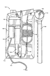
be
coupled to the other of the lower body link or the upper body link. The system
further includes an adjustable force mechanism coupled to at least one of the
first
member and the second member. The adjustable force mechanism includes an
actuator coupled to the first member, the actuator including a motor
configured to
.. selectively apply an adjustable force to the second member to inhibit
rotation of
the first member with respect to the second member.
[0006] According to another embodiment, an exoskeleton is disclosed. The
exoskeleton includes an upper body exoskeleton including an upper body link.
The exoskeleton further includes a lower body exoskeleton including a lower
.. body link. The exoskeleton further includes a hip joint. The hip joint
includes a
first member rotatable about a hip joint rotation axis, the first member
coupled to
one of the lower body link or the upper body link. The hip joint further
includes a
second member rotatable about the hip joint rotation axis, the second member
coupled to the other of the lower body link or the upper body link. The
.. exoskeleton further includes an adjustable force mechanism coupled to at
least
one of the first member and the second member. The adjustable force
mechanism includes an actuator coupled to the first member, the actuator
including a motor configured to selectively apply an adjustable force to the
second member to inhibit rotation of the upper body exoskeleton with respect
to
the lower body exoskeleton.
3
[0007] According to another embodiment, a method of operating a hip
joint of
an exoskeleton is disclosed. The method includes determining, by a controller,
a
torque associated with a hip joint of an exoskeleton. The hip joint includes a
first
member configured to be coupled to one of a lower body link or an upper body
link and a second member rotatable with respect to the first member. The
second member is configured to be coupled to the other of the lower body link
or
the upper body link. The method further includes operating a motor coupled to
one of the first member or the second member to selectively apply an
adjustable
force to the other of the first member or the second member in response to the
determined torque to inhibit rotation of the upper body connection location
with
respect to the lower body connection location.
[0007a] In accordance with another embodiment, there is provided a system
comprising: a hip joint comprising: a first member rotatable about a hip joint
rotation axis, the first member configured to be coupled to one of a lower
body
link or an upper body link; and a second member rotatable about the hip joint
rotation axis, the second member configured to be coupled to the other of the
lower body link or the upper body link; and an adjustable force mechanism
coupled to at least one of the first member and the second member, the
adjustable force mechanism comprising: an actuator coupled to the first
member,
the actuator comprising a motor configured to selectively apply an adjustable
force to the second member to inhibit rotation of the first member with
respect to
the second member; and a controller in communication with the sensor, the
controller configured to: receive a force signal from a sensor; determine,
based
on the force signal, a torque load associated with the hip joint; and operate
the
motor, in response to the determined torque load, to selectively apply the
adjustable force to maintain the torque load within a predetermined range.
[0007b] In accordance with another embodiment, there is provided an
exoskeleton comprising: an upper body exoskeleton comprising an upper body
link; a lower body exoskeleton comprising a lower body link; and a hip joint
comprising: a first member rotatable about a hip joint rotation axis, the
first
member coupled to one of the lower body link or the upper body link; and a
CA 3063399 2020-01-09
3a
second member rotatable about the hip joint rotation axis, the second member
coupled to the other of the lower body link or the upper body link; and an
adjustable force mechanism coupled to at least one of the first member and the
second member, the adjustable force mechanism comprising: an actuator
coupled to the first member, the actuator comprising a motor configured to
selectively apply an adjustable force to the second member to inhibit rotation
of
the upper body exoskeleton with respect to the lower body exoskeleton; and a
controller in communication with the sensor, the controller configured to:
receive
a force signal from a sensor; determine, based on the force signal, a torque
load
associated with the hip joint; and operate the motor, in response to the
determined torque load, to selectively apply the adjustable force to maintain
the
torque load within a predetermined range.
[0007c] In accordance with another embodiment, there is provided a method of
operating a hip joint of an exoskeleton comprising: receiving, by a
controller, a
force signal from a sensor; determining, by the controller, a torque load
associated with a hip joint of an exoskeleton based on the force signal, the
hip
joint comprising a first member configured to be coupled to one of a lower
body
link or an upper body link and a second member rotatable with respect to the
first
member, the second member configured to be coupled to the other of the lower
body link or the upper body link; and operating a motor coupled to one of the
first
member or the second member to selectively apply an adjustable force to the
other of the first member or the second member in response to the determined
torque load to inhibit rotation of the first member with respect to the second
member to maintain the torque load within a predetermined range.
[0008] Those skilled in the art will appreciate the scope of the disclosure
and
realize additional aspects thereof after reading the following detailed
description
of the embodiments in association with the accompanying drawing figures.
CA 3063399 2020-01-09
=
3b
BRIEF DESCRIPTION OF THE DRAWINGS
[0009] The accompanying drawing figures incorporated in and forming a
part
of this specification illustrate several aspects of the disclosure, and
together with
the description serve to explain the principles of the disclosure.
[0010] Figure 1 is a side view of an exoskeleton according to one
embodiment;
[0011] Figure 2 is a first exploded view of a hip joint according to
one
embodiment;
[0012] Figure 3 is a second exploded view of the hip joint
illustrated in Figure
2;
[0013] Figure 4 is a perspective few of the hip joint in an
operational state
according to one embodiment;
[0014] Figure 5 is a diagram of the hip joint illustrated in Figures
3 and 4
wherein the hip joint is integrated with a lower body link and an upper body
link
during manufacturing;
[0015] Figure 6 illustrates a hip joint according to another
embodiment;
CA 3063399 2020-01-09
CA 03063399 2019-11-12
WO 2018/213427
PCT/US2018/032940
4
[0016] Figure 7 illustrates a hip joint according to another embodiment;
[0017] Figure 8 illustrates a hip joint according to another embodiment;
[0018] Figure 9 illustrates an internal view of an adjustable force
mechanism
for a hip joint, according to another embodiment;
[0019] Figure 10 illustrates an actuator suitable for use as part of an
adjustable force mechanism, according to another embodiment;
[0020] Figure 11 is a side view of an exoskeleton being worn by a user,
including an adjustable force mechanism according to another embodiment;
[0021] Figure 12 is a perspective view of the adjustable force mechanism
of
the exoskeleton of Figure 11;
[0022] Figures 13A-13C are side views of an adjustable force mechanism
for
a hip joint in different positions during rotation of the hip joint, according
to
another embodiment;
[0023] Figures 14A-14C are side views of the adjustable force mechanism
for
the hip joint of Figures 13A-13C including a housing for enclosing the
adjustable
force mechanism and portions of the hip joint; and
[0024] Figure 15 is a block diagram of a controller configured to
operate an
adjustable force mechanism for a hip joint, according to another embodiment.
DETAILED DESCRIPTION
[0025] The embodiments set forth below represent the information to
enable
those skilled in the art to practice the embodiments and illustrate the best
mode
of practicing the embodiments. Upon reading the following description in light
of
the accompanying drawing figures, those skilled in the art will understand the
concepts of the disclosure and will recognize applications of these concepts
not
particularly addressed herein. It should be understood that these concepts and
applications fall within the scope of the disclosure and the accompanying
claims.
[0026] The use herein of ordinals in conjunction with an element is
solely for
distinguishing what might otherwise be similar or identical labels, such as
"first
member" and "second member" and does not imply a priority, a type, an
importance, or other attribute, unless otherwise stated herein. The term
"about"
CA 03063399 2019-11-12
WO 2018/213427
PCT/US2018/032940
used herein in conjunction with a numeric value means any value that is within
a
range of ten percent greater than or ten percent less than the numeric value.
[0027] The embodiments relate to a variable force exoskeleton hip joint
having a rotation axis. The variable force exoskeleton hip joint includes an
5 adjustable force mechanism that is configured to apply an adjustable
force to an
upper body link of an upper body exoskeleton with respect to a lower body link
of
a lower body exoskeleton to hinder rotation of the upper body exoskeleton with
respect to the lower body exoskeleton in a rotational direction. Among other
advantages, the variable force exoskeleton hip joint counters the weight of an
item carried in front of or behind the exoskeleton without a need for
counterweights, resulting in a lower weight for a user to manipulate when
moving
the exoskeleton.
[0028] Figure 1 is a side view of an exoskeleton 10 according to one
embodiment. The exoskeleton 10 includes an upper body exoskeleton 12 and a
lower body exoskeleton 14. The upper body exoskeleton 12 includes an upper
body link 16, sometimes referred to as a hip arc, that is coupled to a hip
joint 18.
The hip joint 18 includes a rotation axis 19 that is perpendicular to a
sagittal
plane of a user about which the upper body link 16, and the upper body
exoskeleton 12, can at least partially rotate. In the orientation illustrated
in Figure
1, the lower portion of the upper body exoskeleton 12 includes the upper body
link 16, and the lower body exoskeleton 14 is that portion of the exoskeleton
10
that is below the upper body link 16. The upper body link 16 at least
partially
encloses the hips of the user (not illustrated for purposes of clarity) and,
in
operation, is generally in a substantially horizontal plane.
[0029] The hip joint 18 is also coupled to a lower body link 20 of the
lower
body exoskeleton 14. The lower body link 20, in this example, is a thigh link,
but
in other embodiments, the lower body link 20 may a pelvic link. The lower body
link 20, in the orientation illustrated in Figure 1, in operation is generally
in a
vertical plane. The lower body link 20 and the lower body exoskeleton 14 can
at
.. least partially rotate in the sagittal plane about the rotation axis 19 of
the hip joint
18.
CA 03063399 2019-11-12
WO 2018/213427
PCT/US2018/032940
6
[0030] In this embodiment, the lower body exoskeleton 14 includes a knee
joint 22. The knee joint 22 is also connected to a calf link 24 that extends a
distance along a calf of the user, and terminates at or near a floor. In some
embodiments, the calf link 24 may terminate in a foot rocker 26 that, in
operation,
contacts the floor. In some embodiments, the foot rocker 26 comprises a foot
link, which is positioned under a foot of the user.
[0031] The exoskeleton 10 may also include a tool assembly connector 28
that is configured to support a tool 30 for operation by the user. The tool
assembly connector 28, in this example, is illustrated as being integrated
with the
hip joint 18. The weight of the tool 30 creates a moment of force about the
rotation axis 19. In conventional exoskeletons, this moment of force is
countered
by placing one or more weights on a weight extension 32 that is coupled to the
upper body link 16. Heavy tools 30 require heavy weights on the weight
extension 32, can make the exoskeleton 10 difficult to manipulate for the
user,
and in some circumstances may become a safety concern.
[0032] As will be discussed in greater detail below, the hip joint 18
may
reduce or eliminate the need for weights by allowing the user to manipulate a
user adjustable force mechanism of the hip joint 18 to hinder rotation of the
upper
body link 16 about the rotation axis 19 with respect to the lower body link 20
in a
rotational direction 34. In other embodiments, for example in an exoskeleton
wherein the user carries a workload on a back portion of the upper body
exoskeleton 12, the hip joint 18 may be arranged to hinder rotation of the
upper
body link 16 about the rotation axis 19 with respect to the lower body link 20
in a
rotational direction 36.
[0033] Figure 2 is a first exploded view of a hip joint 18-1 comprising an
adjustable force mechanism according to one embodiment. The hip joint 18-1
has the rotation axis 19 about which a first member 38 rotates. The first
member
38 has a cup shape, and a lower body connection location 40 for connection or
direct coupling with the lower body link 20 (Figure 1). In some embodiments,
the
lower body connection location 40 and the lower body link 20 are integrated
with
one another and formed together during manufacturing. In other embodiments,
CA 03063399 2019-11-12
WO 2018/213427
PCT/US2018/032940
7
the lower body connection location 40 is separate from the lower body link 20
and is subsequently coupled to the lower body link 20 after manufacture.
[0034] The first member 38 comprises a planar face 42 on which a
plurality of
angled pawl teeth 44 are annularly disposed. The first member 38 forms a void
46 in which a ratchet drum 48 resides. The ratchet drum 48 forms a void 50
configured to receive a portion of a torsion spring 52 and a first spring leg
54.
The torsion spring 52 has a rotation axis that is collinear with the rotation
axis 19.
The first spring leg 54 is rotationally coupled to the first member 38 via the
ratchet drum 48 to thereby impart torque upon the first member 38 when
twisted.
A stop 56 is positioned or otherwise formed in the void 50 and is configured
to
limit rotation of the first spring leg 54 in the void 50. A second member 58
also
rotates about the rotation axis 19. The second member 58 has a cup shape and
has an upper body connection location 60 for connection or direct coupling
with
the upper body link 16 (Figure 1). In some embodiments, the upper body
connection location 60 and the upper body link 16 are integrated with one
another, and formed together during manufacturing. In other embodiments, the
upper body connection location 60 is separate from the upper body link 16 and
is
subsequently coupled to the upper body link 16 after manufacture.
[0035] The second member 58 forms an interior void (illustrated in
Figure 3) in
which a cup 62 is positioned. The cup 62 includes a planar face 64 and a
plurality of extensions 66 extending therefrom.
[0036] The first member 38, ratchet drum 48, torsion spring 52, cup 62,
and
second member 58 each form respective openings in which a shaft 68 is
positioned, and about which the various components can at least partially
rotate.
[0037] Figure 3 is a second exploded view of the hip joint 18-1. The
ratchet
drum 48 includes a planar face 70 on which a plurality of angled ratchet teeth
72
are disposed. The angled ratchet teeth 72 and angled pawl teeth 44 (Figure 2)
are configured to allow rotation in a first rotational direction 74 of the
angled
ratchet teeth 72 with respect to the angled pawl teeth 44 when in contact with
one another, and to prohibit rotation in a second rotational direction 76 of
the
CA 03063399 2019-11-12
WO 2018/213427
PCT/US2018/032940
8
angled ratchet teeth 72 with respect to the angled pawl teeth 44 when in
contact
with one another.
[0038] The cup 62 is coupled between the torsion spring 52 and the
second
member 58. The cup 62 forms an interior void 80 configured to receive a second
spring leg 78 of the torsion spring 52, and a stop 82 positioned in the
interior void
80 configured to limit rotation of the second spring leg 78. The second spring
leg
78 is rotationally coupled to the second member 58 via the cup 62 to thereby
impart torque upon the second member 58 when twisted. The second member
58 has a planar face 84 and a plurality of openings 86 configured to receive
the
plurality of extensions 66 (Figure 2) to prevent rotation of the cup 62 with
respect
to the second member 58.
[0039] In operation, a tool, such as a key 88, may be inserted into a
slotted
opening 90 and may be rotated, which in turn rotates the ratchet drum 48. As
the
ratchet drum 48 rotates, the torsion spring 52 rotates, increasing the
torsional
.. force imparted by the torsion spring 52. When a desired amount of pre-
loaded
torsional force is generated, the key 88 may be withdrawn, and the ratchet
drum
48 is prevented from rotating in the second rotational direction 76 by the
pawl
teeth 44. Thus, an adjustable force may be applied to the first member 38 and
the second member 58 to inhibit rotation of the first member 38 and the second
member 58 in a particular rotational direction. The amount of torsional force
provided differs depending on the pre-loaded torsional force, and upon
characteristics of the torsion spring 52. For applications wherein relatively
heavy
tools 30 may be used, a relatively thick torsion spring 52 that can apply
relatively
high torsional forces may be utilized in the hip joint 18-1.
[0040] In operation, if it is desired that the adjustable force be
eliminated, an
elongated tool (not illustrated) may be inserted into a release opening 92 to
disengage the ratchet teeth 72 from the pawl teeth 44, and thereby allow the
torsion spring 52 to rapidly unwind.
[0041] Figure 4 is a perspective view of the hip joint 18-1 in an
operational
state according to one embodiment. A bolt 94 or other structure holds the hip
joint 18-1 together. When a tool 30 is coupled to the exoskeleton 10, the key
88
CA 03063399 2019-11-12
WO 2018/213427
PCT/US2018/032940
9
(Figure 3) or other tool may be inserted into slots 96 to variably adjust the
rotational forces provided by the hip joint 18-1 to counter the weight of the
tool
30. When the tool 30 is removed from the exoskeleton 10, an elongated tool
(not
illustrated) may be inserted into the release opening 92 to disengage the
ratchet
teeth 72 from the pawl teeth 44, and thereby allow the torsion spring 52 to
rapidly
unwind, such that the hip joint 18-1 provides no rotational force.
[0042] In one embodiment, the hip joint 18-1 has a preloaded mode and a
non-preloaded mode. In the non-preloaded mode, the upper body connection
location 60 is at about a 90 degree orientation with respect to the lower body
connection location 40.
[0043] Figure 5 is a diagram of a hip joint 18-2 wherein the hip joint
18-2 is
integrated with the lower body link 20 and the upper body link 16 during
manufacturing. The lower body link 20 is at least partially rotatable about
the
rotation axis 19 (Figure 4), and includes a lower body link hip joint end 61
and a
lower body link distal end 63. The upper body link 16 is also at least
partially
rotatable about the rotation axis 19. The upper body link 16 has an upper body
link hip joint end 65. The hip joint 18-2 is otherwise identical to the hip
joint 18-1
as discussed above.
[0044] Figure 6 illustrates a hip joint 18-3A according to another
embodiment.
The tool assembly connector 28 is not illustrated for purposes of clarity. In
this
embodiment, parts of an adjustable force mechanism 98 are housed in either the
upper body link 16 or the lower body link 20. In this embodiment, the upper
body
link 16 includes a shaft 100. The lower body link 20 includes a ring member
102
that is fixed with respect to the lower body link 20 and that is capable of at
least
partial rotation about the shaft 100.
[0045] A rod 104 is coupled at one end 106 to the ring member 102 via a
hinge 108. Another end 110 of the rod 104 is coupled to an extension spring
112. The extension spring 112 is also coupled to a disk 114 that has a
perimeter
shaped to fit snugly within a chamber 116 of the upper body link 16, but is
capable of movement along a longitudinal axis of the upper body link 16. The
disk 114 forms a threaded opening that receives a threaded rod 118. A rotation
CA 03063399 2019-11-12
WO 2018/213427
PCT/US2018/032940
mechanism 120 is configured to rotate the threaded rod 118 to slide the disk
114
with respect to the upper body link 16 and thereby apply tension to the
extension
spring 112. Increases in tension of the extension spring 112 increase the
amount of force necessary to rotate the upper body link 16 with respect to the
5 lower body link 20 in a rotational direction 122.
[0046] In one embodiment, the rotation mechanism 120 comprises a ratchet
and pawl mechanism, and includes a user-selectable quick release mechanism
which, when activated, allows the extension spring 112 to rapidly return to a
non-
tensioned state.
10 [0047] While for purposes of illustration the adjustable force
mechanism 98 is
depicted as being housed in the upper body link 16, it will be apparent that
the
adjustable force mechanism 98 could alternatively be housed in the lower body
link 20. In such embodiment, the lower body link 20 may include the shaft 100,
and the upper body link may include the ring member 102.
[0048] Figure 7 illustrates a hip joint 18-3B according to another
embodiment.
The hip joint 18-3B is substantially similar to the hip joint 18-3A
illustrated in
Figure 6, except that the hip joint 18-3B includes an actuator 97. The
actuator 97
includes an actuator motor 99 and an actuator arm 101. The motor 99 is housed
within and fixed with respect to the upper body link 16. The motor 99 is
configured to selectively extend or retract the actuator arm 101 in response
to
actuation of a switch 103 by the user. The position of the actuator arm 101
determines the force imparted upon the ring member 102 via the rod 104 and the
extension spring 112.
[0049] Figure 8 illustrates a hip joint 18-4 according to another
embodiment.
.. The tool assembly connector 28 is not illustrated for purposes of clarity.
In this
embodiment, parts of an adjustable force mechanism 124 are housed in either
the upper body link 16 or the lower body link 20. In this embodiment, the
upper
body link 16 includes the shaft 100. The lower body link 20 includes the ring
member 102 that is fixed with respect to the lower body link 20 and that is
capable of at least partial rotation about the shaft 100.
CA 03063399 2019-11-12
WO 2018/213427
PCT/US2018/032940
11
[0050] A rod 126 is coupled at one end 128 to the ring member 102 via a
hinge 130. Another end 132 of the rod 126 is hingedly coupled to an actuator
arm 134 of an actuator 140. The actuator 140 includes a motor 142. The motor
142 is housed within and fixed with respect to the upper body link 16. The
motor
142 is configured to selectively extend or retract the actuator arm 134. The
position of the actuator arm 134 determines the relative location of the upper
body link 16 with respect to the lower body link 20. In one embodiment, once
set
in a desired position, the actuator arm 134 maintains the relative location of
the
upper body link 16 with respect to the lower body link 20 in a fixed position,
thereby preventing rotation of the upper body link 16 with respect to the
lower
body link 20. In other embodiments, control circuitry 143 allows, upon a
predetermined amount of force, controlled lateral movement of the actuator arm
134 to permit rotation of the upper body link 16 with respect to the lower
body link
20.
[0051] The actuator arm 134 may have a neutral position, such that no force
is applied to the ring member 102 and such that the upper body link 16 may
rotate unhindered with respect to the lower body link 20. A user-selectable
variable switch 148 may allow the user to operate the motor 142 to extend the
actuator arm 134 to a desired position, retract the actuator arm 134 to a
desired
position, or place the actuator arm 134 in the neutral position.
[0052] While for purposes of illustration the adjustable force mechanism
124
is depicted as being housed in the upper body link 16, it will be apparent
that the
adjustable force mechanism 124 could alternatively be housed in the lower body
link 20. In such embodiment, the lower body link 20 may include the shaft 100,
and the upper body link may include the ring member 102.
[0053] Figure 9 illustrates an internal view of a system 150 including a
hip
joint 152 having an adjustable force mechanism, according to another
embodiment. The hip joint 152 has a rotation axis 154, which permits rotation
of
a lower body link 156 with respect to the hip joint 152. In this embodiment,
the
hip joint 152 includes an adjustable force mechanism 158 comprising a motor
160 operably coupled to a piston mechanism 162. An extension spring 164 is
CA 03063399 2019-11-12
WO 2018/213427
PCT/US2018/032940
12
coupled between the lower body link 156 and the piston mechanism 162 to
provide passive resistance against rotation of the lower body link 156,
similar to
the extension spring 112 of Figure 6 above, for example. In this embodiment,
the
extension spring 164 is coupled to a movable piston 166 of the piston
mechanism 162 via a cable 168, and is coupled to the lower body link 156 via
another cable 170.
[0054] The piston 166 is selectively movable by the piston mechanism 162
to
increase or decrease an amount of tension in the extension spring 164, thereby
increasing or decreasing a resistance to rotation of the lower body link 156
with
respect to the hip joint 152. In this embodiment, the adjustable force
mechanism
158 and extension spring 164 are contained within a housing 172 to protect the
component parts of the adjustable force mechanism 158 and extension spring
164. In this example, a power cable 174 is connected to the motor 160 and is
configured to provide a power signal configured to operate the motor 160 in
order
to selectively move the piston 166. As will be discussed in greater detail
with
respect to Figure 15 below, the power signal may be selectively and/or
automatically provided by a controller based on a predetermined controller
logic.
[0055] According to another embodiment, Figure 10 illustrates an
actuator
176 suitable for use as part of an adjustable force mechanism, such as the
adjustable force mechanism 158 of Figure 9 above, for example. In this
example, the actuator 176 includes a motor 178 coupled to a screw mechanism
180 via a drive belt 182. The screw mechanism 180 is configured to extend or
retract a screw piston 184 in response to rotation of the drive belt 182 by
the
motor 178. The actuator 176 in this embodiment is configured to be coupled to
a
lower body link of an exoskeleton. A bolt aperture 186 is disposed at the
distal
end of the screw piston 184 for engaging with a hip link of the exoskeleton to
facilitate or inhibit rotation of the lower body link with respect to the hip
link. A
power cable 187 is configured to provide electrical power and/or signals to
the
motor 178 for selectively or automatically driving the motor 178.
[0056] Figure 11 is a side view of an exoskeleton 188 being worn by a user
190, according to another embodiment. In this example, similar to the
CA 03063399 2019-11-12
WO 2018/213427
PCT/US2018/032940
13
exoskeleton 10 of Figure 1 above, the exoskeleton 188 includes an upper body
link 192 configured to support equipment, such as the tool 30, and a lower
body
link 194 rotatably coupled to the upper body link 192 via a hip link 196. The
lower body link 194 is rotatable with respect to the hip link 196 via a hip
joint 198
having a rotation axis 200. In this example, the hip joint 198 is manually
lockable
via a locking lever 201, to selectively inhibit or facilitate rotation of the
lower body
link 194 with respect to the hip link 196. The lower body link 194 also
includes
thigh link 202, knee joint 204, calf link 206, a rocker mechanism 208, and a
foot
link 210 similar to the lower body link 20 of Figure 1 above, for example.
[0057] An adjustable force mechanism 212, similar to the adjustable force
mechanism 158 of Figure 9 above, is coupled to the hip link 196, and
configured
to selectively or automatically facilitate or inhibit rotation of the lower
body link
194 with respect to the hip link 196. The adjustable force mechanism 212 may
also be connected to one or more sensors 215. The sensors 215 may be in
communication with a controller to provide input for the controller for
controlling
the operation of the adjustable force mechanism 212. In one embodiment, the
sensors 215 may be configured to detect a force being applied to a portion of
the
exoskeleton 188 and/or the user 190, and generate a force signal indicative of
a
torque being applied thereto. For example, the sensor 215 may be connected to
a back interface 216 configured to interface with a lower back 217 of the user
190 to detect movement of the back interface 216 corresponding to movement of
the lower back 217 of the user 190 and/or otherwise measure a load being
applied to the lower back 217 of the user 190. In response to receiving the
force
signal, the controller may be configured to determine the torque being applied
to
the lower back 217 of the user 190. In one embodiment, the adjustable force
mechanism 212 may be configured to maintain a force on the hip joint 198 such
that the torque being applied to the lower back 217 of the user 190 is
maintained
within a predetermined range corresponding to an acceptable level of exertion
and/or fatigue for the user 190. In another embodiment, the sensor 217 may be
connected to a leg interface 218 coupled to the thigh link 202, wherein the
sensor
CA 03063399 2019-11-12
WO 2018/213427
PCT/US2018/032940
14
215 is connected to the leg interface 218 and configured to detect movement of
the thigh link 202 corresponding to movement of a leg of the user 190.
[0058] Referring now to Figure 12, a perspective view of the adjustable
force
mechanism 212, the adjustable force mechanism 212 includes a housing 214
having an actuation switch 219. In this example, operation of the actuation
switch 219 by the user 190 operates the adjustable force mechanism 212 to
facilitate or inhibit rotation of the lower body link 194 with respect to the
hip link
196. In one example, the actuation switch 219 can be used to manually
calibrate
the controller to maintain the maintain a force on the hip joint 198 such that
the
torque being applied to the lower back 217 of the user 190 is maintained
within a
predetermined range corresponding to an acceptable level of exertion and/or
fatigue for the user 190.
[0059] Figures 13A-130 are side views of a portion of an exoskeleton 220
having a hip link 221 with a hip joint 222 for rotating a lower body link 224
with
respect to the hip link 221 about a rotation axis 225, according to another
embodiment. An adjustable force mechanism 226, similar to the adjustable force
mechanism 176 of Figure 10 above, is configured to provide different levels of
resistance at different positions of the lower body link 224 during rotation
of the
hip joint 222. In this embodiment, the adjustable force mechanism 226 is fixed
with respect to the lower body link 224 and is rotatably coupled to a piston
joint
228 having a rotation axis 230 that is fixed with respect to the hip link 221.
[0060] The adjustable force mechanism 226 may be disposed in a housing
232 and may include a motor 234 configured to selectively or automatically
drive
a piston 236 that is rotatably coupled to the piston joint 228. The adjustable
force
mechanism 226 in this example also includes a spring sensor subassembly 238
configured to deflect in response to forces applied to the hip joint 222. In
response to these minor deflections, the spring sensor subassembly 238 may
provide a signal to a controller (not shown), which in turn operates the
adjustable
force mechanism 226 to facilitate or inhibit rotation of the lower body link
224 with
respect to the hip link 221. Thus, as the load, e.g., weight, carried by the
exoskeleton 220 increases, the amount of force required by a user to maintain
CA 03063399 2019-11-12
WO 2018/213427
PCT/US2018/032940
the lower body link 224 in a particular position with respect to the hip link
221 can
be maintained or adjusted as needed, based on feedback from the spring sensor
subassembly 238, thereby reducing fatigue and the risk of accident or injury.
[0061] Figures 14A-14C are side views of the adjustable force mechanism
5 226 for the hip joint 222 of Figures 13A-13C including an upper housing
member
240 and a lower housing member 242 for enclosing the adjustable force
mechanism 226. In this example, the upper housing member 240 is slidable with
respect to the lower housing member 242 to accommodate extension or
retraction of the piston 236 while keeping the adjustable force mechanism 226
10 enclosed. A hip joint housing member 244 is also provided to enclose and
protect components of the hip joint 222.
[0062] Figure 15 is a block diagram of a controller 246, such as a
computing
device for example, suitable for implementing the functionality of various
components discussed herein, such as operation of the adjustable force
15 .. mechanisms described above. In some embodiments, such components may be
implemented on separate controllers 246. In other embodiments, certain of the
components may be implemented on a single controller 246. These are merely
examples, and the particular implementation of functionality versus individual
controllers 246 may be system- and design-dependent.
[0063] The controller 246 may comprise any computing or processing device
capable of including firmware, hardware, and/or executing software
instructions
to implement the functionality described herein for the respective component.
The controller 246 includes a central processing unit 248, sometimes referred
to
as a processor or micro-processor, a system memory 250, and a system bus
252. The system bus 252 provides an interface for system components
including, but not limited to, the system memory 250 and the central
processing
unit 248. The central processing unit 248 can be any commercially available or
proprietary processor.
[0064] The system bus 252 may be any of several types of bus structures
that
may further interconnect to a memory bus (with or without a memory
controller),
a peripheral bus, and/or a local bus using any of a variety of commercially
CA 03063399 2019-11-12
WO 2018/213427
PCT/US2018/032940
16
available bus architectures. The system memory 250 may include non-volatile
memory 254 (e.g., read only memory (ROM), erasable programmable read only
memory (EPROM), electrically erasable programmable read only memory
(EEPROM), etc.) and/or volatile memory 256 (e.g., random access memory
(RAM)). A basic input/output system (BIOS) 258 may be stored in the non-
volatile memory 254, and can include the basic routines that help to transfer
information between elements within the controller 246. The volatile memory
256
may also include a high-speed RAM, such as static RAM for caching data.
[0065] The controller 246 may further include or be coupled to a
computer-
readable storage 262, which may comprise, for example, an internal or external
hard disk drive (HDD) (e.g., enhanced integrated drive electronics (FIDE) or
serial advanced technology attachment (SATA)), HDD (e.g., EIDE or SATA) for
storage, flash memory, or the like. The computer-readable storage 262 and
other drives, associated with computer-readable media and computer-usable
media, may provide non-volatile storage of data, computer-executable
instructions, and the like. Although the description of computer-readable
media
above refers to an HDD, it should be appreciated by those skilled in the art
that
other types of media which are readable by a computer, such as a solid state
drives (SSD), floppy disks, magnetic cassettes, flash memory drives, flash
memory cards, cartridges, optical media, and the like, may also be used in the
exemplary operating environment, and further, that any such media may contain
computer-executable instructions for performing novel methods of the disclosed
architecture.
[0066] A number of modules can be stored in the computer-readable
storage
262 and in the volatile memory 256, including an operating system 260 and one
or more program modules 264, which may implement the functionality described
herein in whole or in part. For example, the program modules 264 may include
algorithms for selectively or automatically operating one of the adjustable
force
mechanisms 158, 176, 212, 226 of Figures 9-14C above, such as by operating
one of the motors 160, 178, 234 for example.
CA 03063399 2019-11-12
WO 2018/213427
PCT/US2018/032940
17
[0067] All or a portion of the embodiments may be implemented as a
computer program product stored on a transitory or non-transitory computer-
usable or computer-readable storage medium, such as the computer-readable
storage 262, which includes complex programming instructions, such as complex
computer-readable program code, configured to cause the central processing
unit 248 to carry out the steps described herein. Thus, the computer-readable
program code can comprise software instructions for implementing the
functionality of the embodiments described herein when executed on the central
processing unit 248. The central processing unit 248, in conjunction with the
program modules 264 in the volatile memory 256, may serve as a controller, or
control system, for the controller 246 that is configured to, or adapted to,
implement the functionality described herein. The controller 246 may also
include a communication interface 266, suitable for communicating with the
adjustable force mechanisms described above, and/or for communicating with
other computing devices directly or via a network, as desired.
[0068] Those skilled in the art will recognize improvements and
modifications
to the preferred embodiments of the disclosure. All such improvements and
modifications are considered within the scope of the concepts disclosed herein
and the claims that follow.