Note: Descriptions are shown in the official language in which they were submitted.
- 1 -
ROOF VENT WITH INTEGRATED SHIELD
[0001]
FIELD
[0002] This disclosure relates generally to roof vents for venting the
roof of a
building such as a house.
BACKGROUND
[0003] Roof vents provide the necessary ventilation to the roof of a
house or
other building, inhibiting condensation in the roof due to the infiltration or
otherwise
collection of moisture into the roof or attic cavity. Various roof vents
employ vanes,
grates and louvers to permit air to be channeled between the roof and the
atmosphere,
and to try to inhibit rain from entering the roof through the roof vent. A
variety of caps
and covers have been used to act as a guard to prevent the infiltration of
rain. However,
prior art roof vents have thus far been ineffective in inhibiting the
infiltration of water into
the attic space, particularly in cases of fierce storms and the like.
[0004] Of particular concern for roof mounted vents is the infiltration
of water.
Roof vents mounted lower down on the roof, nearer the eves, can be
particularly
susceptible to fast/voluminous moving water coming down the roofing surface
and
impacting the sides of the roof vent. It is recognized that the greater the
speed and/or
volume of water impacting the sides of the roof vent, the greater the risk of
water
infiltrating the roof vent and finding its way in to the interior of the roof.
Also of concern
is the positioning of multiple auxiliary structures on the roof, such as
vents, as the
auxiliary structures must be tied into the roof cladding (e.g. shingles), and
as such can
present potential weaknesses in the roof cladding. Further, care must be taken
by
installers with the individually positioned auxiliary structures, as each
auxiliary structure
must be tied in properly with the roof cladding about the auxiliary structure.
Date Recue/Date Received 2022-06-01
CA 03063778 2019-11-15
WO 2018/209424 PCT/CA2018/000096
- 2 -
As the number of individual auxiliary structures increases, the amount of time
and
expense for installation also increases. Further, some roof geometries present
limited
space opportunities for the positioning of the auxiliary structures.
[0005] As such, it is recognized for any or all of the disadvantages
above,
minimizing the number of auxiliary structures mounted on a roof surface is
preferred.
SUMMARY
[0006] It is an object of the present invention to provide a roof vent
that obviates
or mitigates at least some of the above-presented disadvantages in the art.
[0007] An improved roof vent which facilitates adequate attic ventilation
but at
the same time inhibits the infiltration of snow particles, water droplets,
water runoff of
the roof surface, burning cinders, and/or other undesirable elements from the
atmosphere from gaining entry into the roof via the roof vent is desired.
[0008] A first aspect provided is a roof vent for ventilating a roof of a
building via
a hole in the roof to atmosphere, the roof vent comprising: a flange portion
for resting
on the roof, the flange portion having an opening for overlapping with the
hole; a frame
portion for maintaining a cap in a spaced apart relationship with the flange
portion; the
cap connected to the frame portion and covering over the opening; and a
corrugated
or non-corrugated filter plate extending between the cap and the flange
portion and
interposed transversely between the opening and the atmosphere, the corrugated
or
non-corrugated filter plate providing for a passage of air between the
atmosphere and
the opening, the corrugated or non-corrugated filter plate having a pore size
sufficient
for facilitating the air passage of air through the corrugated or non-
corrugated filter
plate while blocking passage of water through the corrugated or non-corrugated
filter
plate.
[0009] A second aspect provided is a roof vent for ventilating a roof of a
building
via a hole in the roof to atmosphere, the roof vent comprising: a flange
portion for
resting on the roof, the flange portion having an opening for overlapping with
the hole;
a frame portion for maintaining a cap in a spaced apart relationship with the
flange
CA 03063778 2019-11-15
WO 2018/209424 PCT/CA2018/000096
- 3 -
portion; the cap connected to the frame portion and covering over the opening;
an
integrated shield mounted on the flange portion and extending transverse to
the flange
portion on a side of the flange portion configured for facing a peak of the
roof, the
integrated shield spaced apart from the frame portion by a predefined distance
and for
deflecting water running down the roof to either side of the roof vent; and a
corrugated
or non-corrugated filter plate extending between the cap and the flange
portion and
interposed transversely between the opening and the atmosphere, the corrugated
or
non-corrugated filter plate providing for a passage of air between the
atmosphere and
the opening, the corrugated or non-corrugated filter plate having a pore size
sufficient
for facilitating the air passage of air through the corrugated or non-
corrugated filter
plate while blocking passage of water through the corrugated or non-corrugated
filter
plate.
[0010] A third aspect provided is a roof vent for ventilating a roof of a
building
via a hole in the roof to atmosphere, the roof vent comprising: a flange
portion for
resting on the roof, the flange portion having an opening for overlapping with
the hole;
a frame portion for maintaining a cap in a spaced apart relationship with the
flange
portion; the cap connected to the frame portion and covering over the opening;
and an
integrated shield mounted on the flange portion and extending transverse to
the flange
portion on a side of the flange portion configured for facing a peak of the
roof, the
integrated shield spaced apart from the frame portion by a predefined distance
and for
deflecting water running down the roof to either side of the roof vent.
BRIEF DESCRIPTION OF THE DRAWINGS
[0011] The foregoing and other aspects will now be described by way of
example only with reference to the attached drawings, in which:
[0012] FIG. 1 is a perspective view of a roof vent;
[0013] FIG. 2 is a side view of the roof vent shown in FIG. 1;
[0014] FIG. 3 is a cross sectional view of the roof vent shown in FIG. 2;
CA 03063778 2019-11-15
WO 2018/209424 PCT/CA2018/000096
- 4 -
[0015] FIG. 4 is a top view of an optional collar portion of the roof vent
shown in
FIG. 1;
[0016] FIG. 5 is a cross sectional view of the collar portion shown in
FIG. 4;
[0017] FIG. 6 is a top view of the collar portion with a corrugated filter
plate of
the roof vent shown in FIG. 1;
[0018] FIG. 7 is a perspective view of a portion of the filter plate
portion of the
roof vent shown in FIG. 1;
[0019] FIG. 8 is an alternative embodiment the cross sectional view of the
roof
vent shown in FIG 3;
[0020] FIG. 9 is a further alternative embodiment the cross sectional view
of the
roof vent shown in FIG 3;
[0021] FIG. 10 is a further alternative embodiment the cross sectional
view of
the roof vent shown in FIG 3;
[0022] FIG. 11a is an alternative embodiment of the roof vent shown in FIG
1;
[0023] FIG. llb is an alternative embodiment of the roof vent shown in FIG
1;
[0024] FIG. 12 is a further alternative embodiment the cross sectional
view of
the roof vent shown in FIG 3;
[0025] FIG. 13 is a further alternative embodiment the cross sectional
view of
the roof vent shown in FIG 3;
[0026] FIG. 14 is an alternative embodiment of the roof vent shown in FIG
4;
[0027] FIG. 15 is a perspective view of the roof vent shown in FIG 14 with
cap
attached;
[0028] FIG. 16 is a perspective view of the roof vent shown in FIG 14
without
cap attached;
[0029] FIG. 17 is an insert as an alternative embodiment of the roof vent
shown
in FIG 1;
[0030] FIG. 18 is an alternative embodiment of the insert of FIG 17;
CA 03063778 2019-11-15
WO 2018/209424 PCT/CA2018/000096
- 5 -
[0031] FIG. 19 is a further alternative embodiment of the insert shown in
FIG 18;
[0032] Figure 20 shows an alternative embodiment of the roof vent of
Figure1
including an integrated shield
[0033] Figure 21 shows a perspective side view of the vent of Figure 20;
[0034] Figure 22 shows a perspective top view of the vent of Figure 20;
[0035] Figure 23 shows a perspective top view of the vent of Figure 20
unassembled;
[0036] Figure 24 shows a side view of the vent of Figure 20 unassembled;
[0037] Figure 25a shows a top view of the vent of Figure 20 unassembled;
[0038] Figure 25b shows a perspective top view of an alternative
embodiment of
the vent of Figure 20; and
[0039] Figures 26-27 show alternative embodiments of the filter of Figures
6
and 7.
[0040] In the drawings like characters of reference indicate corresponding
parts
in the different figures.
DETAILED DESCRIPTION
[0041] Figure 1,3 show a roof vent 10 for ventilating the roof of a
building to the
atmosphere. The roof vent 10 includes a flange portion 12 to lay against the
roof, the
flange portion 12 having an opening 22 to let air vent from the interior of
the building
(e.g. an attic). The roof vent 10 can optionally include a collar portion 14
extending
from the flange portion 12 and enclosing, at least in part, about a periphery
of the
opening 22, and a cap 16 dimensioned and configured to cover over the opening
22
(including the hole 28 in the roof) and optionally over the collar portion 14.
The cap 16
is configured to provide a passage (between the flange portion 12 and the cap
16)
through which air can pass between the atmosphere and the opening 22. The roof
vent 10 also includes a corrugated filter plate 46, e.g. partially enclosed by
the cap 16,
and interposed between the central opening 22 and the air passage (e.g. gap)
CA 03063778 2019-11-15
WO 2018/209424 PCT/CA2018/000096
- 6 -
between the cap 16 and the flange portion 12. The corrugated filter plate 46
can have
a pore size 47 (e.g. perforations, holes, a plurality of apertures, etc. ¨ see
Fig. 7)
sufficient to facilitate air to pass through the corrugated filter material 46
(e.g. from one
side 19 of the corrugated filter material 46 to the other 19) but inhibit the
passage of
snow particles, cinder particles, running water and/or water droplets there-
through
(e.g. from one side 19 of the corrugated filter material 46 to the other 19).
In any event,
it is recognized that the purpose of the corrugated filter material 46 is to
provide for the
flow through of air while inhibiting the passage of undesirable
particles/droplets (e.g.
solid and/or liquid pieces of matter) through the corrugated filter material
46 impinging
from the atmosphere and into the interior of the roof via the opening 22 and
adjacent
hole 28.
[0042] For example, the corrugated filter material 46 can be positioned as
extending upwardly between the flange portion 12 and the cap 16 (covering the
opening 22). It is recognized that the corrugated filter material 46 can be in
contact
with a top surface 13 of the flange portion 12, in contact with an underside
surface 17
of the cap 16, and/or in contact with the top surface 13 of the flange portion
12 and
with the underside surface 17 of the cap 16. It is recognized that a sidewall
15 (e.g.
collar wall ¨ see Fig. 2) extending upwardly from the top surface 13 of the
flange
portion 12 can also be considered as part of the top surface 13 of the flange
portion
12. It is recognized that a sidewall (not shown) extending downwardly from the
bottom/underside surface 17 of the cap 16 can also be considered as part of
the
bottom/underside surface 17 of the cap 16.
[0043] Corrugated (see Fig. 7) can refer to draws or bends into folds or
alternate furrows and ridges of the surface of the filter plate 46. A
corrugated surface
can also refer to a pleated surface 19. A corrugated surface 19 can also refer
to a
shape into folds or parallel and alternating ridges and grooves. The juncture
between
the folds can be well defined (e.g. a crease line) or can be distributed over
the surface
(e.g. an arcuate change in direction from one fold to the next, such as an
arcuate
portion of the surface 19 of the corrugated filter material 46). For example,
the
corrugated filter material 46 (e.g. plate) can be a single walled surface 19
as shown,
CA 03063778 2019-11-15
WO 2018/209424 PCT/CA2018/000096
- 7 -
can be a double walled structure, not shown, (e.g. having a space between
adjacent
walls having a corrugated surface 19, etc). Preferably the corrugated filter
material 46
has a corrugated surface 19 exposed to the passage of air impinging on the
corrugated filter material 46 from the atmosphere and directed towards the
opening 22
(and overlapping hole 28 in the roof membrane of the building) and into the
roof cavity
(e.g. attic space). Preferably the corrugated filter material 46 has a
corrugated surface
19 exposed to the passage of air impinging on the corrugated filter material
46 from
the exiting the roof cavity (e.g. attic space) and directed towards the
opening 22 (and
overlapping hole 28 in the roof membrane 50 of the building) and into the
atmosphere.
[0044] In terms of positioning of the corrugated filter material 46 with
respect to
the cap 16 (at least covering the opening 28) and with respect to the flange
portion 12,
the corrugated filter material 46 is positioned transverse to both of the cap
16 (e.g.
underside surface 17 of the cap 16) and the flange portion 12 (e.g. upper
surface 13 of
the flange portion 12). As such, it is recognized that the corrugated filter
material 46
can be in contact with one of the surfaces 13,17, with both of the surfaces
13, 17,
an/or in contact with none of the surfaces 13,17 (e.g. suspended between the
surfaces
13,17 by a secondary structure that can also be used to position the cap 16 in
a
spaced apart relationship with the flange portion 12. For example, the
secondary
structure can be provided by the collar portion 14 described herein as an
example
only. In any event, the corrugated filter material 46 extends transversely (in
whole, in
part, etc.) between the cap 16 and the flange portion 12 (e.g. base of the
roof vent 10).
In terms of in-whole, then any passage of air between the opening 22 and the
atmosphere would pass though the body of the corrugated filter material 46.
Alternatively, in terms of in- part, some of the passage of air between the
opening 22
and the atmosphere would pass though the body of the corrugated filter
material 46
and passage of air between the opening 22 and the atmosphere would go around
the
body of the corrugated filter material 46. In terms of transverse, this can be
referred to
as situated or lying across (e.g. between the opposing surfaces 13,17), lying
sideways
(e.g. between the opposing surfaces 13,17), crosswise (e.g. between the
opposing
surfaces 13,17), crossing from side to side (e.g. between the opposing
surfaces
13,17), athwart (e.g. between the opposing surfaces 13,17), crossways (e.g.
between
CA 03063778 2019-11-15
WO 2018/209424 PCT/CA2018/000096
- 8 -
the opposing surfaces 13,17), lying or extending across or in a cross
direction (e.g.
between the opposing surfaces 13,17), cross (e.g. between the opposing
surfaces
13,17). One example of transverse (e.g. between the opposing surfaces 13,17)
can
be lying at right angles to or perpendicular to each or both of the opposing
surfaces
13,17). It is also recognized that the angle of the corrugated filter material
46, when
extending away from (either in or out of contact with the actual surface
13,17) the
surface 13,17, can be other than 90 degrees, as desired.
[0045] The roof vent 10 can be considered as a roof vent type for natural
ventilation, as using the process of supplying and removing air through an
indoor
space (e.g. attic) without using mechanical systems. Natural ventilation
implemented
by the roof vent 10 can refer to the flow of external air to an indoor space
as a result of
pressure or temperature differences. There can be two types of natural
ventilation
occurring in buildings: wind driven ventilation and buoyancy-driven
ventilation. While
wind can be the main mechanism of wind driven ventilation, buoyancy-driven
ventilation can occur as a result of the directional buoyancy force that
results from
temperature differences between the interior and exterior of the building.
Alternatively,
natural ventilation can be referred to as Passive ventilation, as a way to
provide attic
ventilation for shingle roof assemblies is by nonpowered, passive ventilation
based
roof vent 10. This method relies primarily on natural air convection¨the
upward
movement of heated air because of its lower density¨but may also take
advantage of
wind-generated pressure differences.
[0046] Natural convection can initiate the upward flow of air through an
attic and
through the roof vent 10. This air current can be maintained to aid in
continuous
circulation of air through the attic if intake vents placed low in the attic
make colder air
available to replace the heated air exhausted through vents placed high in the
attic.
Convection-assisted ventilation can be effective when approximately equal
amounts of
ventilation opening areas are placed at the soffits or eave and at or near the
top of the
attic space, referred to as "balanced ventilation." It is also recognized that
the roof
vent 10 can be a powered type roof vent rather than a passive type. For
example, the
roof vent 10 can have a powered unit, e.g. a fan with corresponding drive
mechanism
CA 03063778 2019-11-15
WO 2018/209424 PCT/CA2018/000096
- 9 -
(e.g. motor) for assisting flow of the passage of air through the corrugated
filter plate
46.
[0047] In terms of the net free cross sectional area for the passage of
air
through the corrugated filter plate 46, the aggregate total open area (e.g.
summation of
the effective open area of each of the individual pore 47 cross sectional
areas) of the
plurality of holes/pores 47 can be configured to satisfy a minimum net open
area
threshold. For example, the open area threshold can be approximately 50 square
inches of flow ability (e.g. net free area) available for the passage of air
to flow
through. It is recognized that the minimum net open area threshold can be a
standard
defined threshold, different for each country, province, and/or state based
building
codes/standards. In an example where the corrugated filter plate 46 does not
extend
from surface 13 to surface 17, the total net free air flow area available
would be the
aggregate of the effective open area of each of the individual pore 47 cross
sectional
areas of the corrugated filter plate 46 and the open cross sectional area of
an air gap
between an end of the filter plate 46 and the adjacent surface 13,17.
[0048] Referring to FIG. 1,3, the roof vent 10 provides for roof
ventilation while
at the same time inhibiting the infiltration of snow, water (e.g. undesired
particles
and/or a series of streaming water) into the attic. The roof vent 10 has the
flange
portion 12, optionally the collar portion 14 (shown as an example embodiment)
and the
cap 16 configured to cover over (e.g. most) of the collar portion 14 and to
cover over a
portion of the surface 19. Flange portion 12 is preferably flat to rest flush
with the roof
(not shown) to make it easy to install the roof vent. Collar portion 14
extends
perpendicularly upward from flange 12. Cap 16 is dimensioned to enclose much
of the
collar portion 14 but to leave a space gap 18 between the cap 16 and flange
portion 12
to permit atmospheric air to pass through collar portion 14.
[0049] Referring now to FIGS. 2 and 3, flange portion 12 has a (e.g.
central)
aperture 22 and collar portion 14 has a (e.g. central) cavity 26 which
communicates
with aperture 22 providing for air to circulate between attic interior 30,
through hole 28
in roof 26 and cavity 26. Collar/frame 14 can have one or more apertures 24
through
which air can circulate between cavity 26 and outside atmosphere 32 through
air
CA 03063778 2019-11-15
WO 2018/209424 PCT/CA2018/000096
- 10 -
passage 20 and a gap 18 (between the flange portion 12 and the cap 16). As can
be
seen in FIGS. 4 and 5, collar portion 14 can be formed as a (e.g. annular)
frame
having upper portion 38, lower portion 40 and sides 36 formed from support
members
34. Apertures 24 are formed between support members 34. The collar portion 14
is
one example of a frame (e.g. frame portion 14) that can provide for structural
rigidity
between the cap 16 and flange portion 12, thus providing for structural
integrity of the
roof vent 10 in keeping the cap 16 at a spaced apart distance from the flange
portion
12. It is also recognized that the frame portion 14 can be separate from the
corrugated filter material 46 (e.g. the frame portion 14 and the corrugated
filter material
46 are separate and distinct pieces of the roof vent 10). It is also
recognized that the
frame portion 14 can be integrated with the corrugated filter material 46
(e.g. the frame
portion 14 and the corrugated filter material 46 are an integrated component
of the roof
vent 10). For example, the frame portion 14 with integrated corrugated filter
material
46 can be attached to both the cap 16 and the flange portion 12, such that the
frame
portion 14 extends away (e.g. upwardly, downwardly, etc.) from the respective
surfaces 13,17. As such, the frame portion 14 and the collar portion 14 can be
used
interchangeably, however recognizing that the frame portion 14 can refer only
to the
support portions keeping the cap 16 spaced apart from the flange portion 12,
while any
solid walls transverse to the flange portion 12 are absent from the frame
portion 14
(see Figure 3). In terms of the collar portion 14, this can have both the
support
portions from holding the cap 16 spaced apart from the flange portion 12 as
well as
have the upstanding walls transverse to the flange portion 12 (see Figure 2).
As further
discussed below, the shield 80 (see Figure 20) can be used to direct running
water
away from the roof vent 10 having the optional collar portion 14 (see Figure
2) having
the upstanding walls surrounding the hole 28 in the roof. Alternatively, as
further
discussed below, the shield 80 (see Figure 20) can be used to direct running
water
away from the roof vent 10 having the frame portion 14 (see Figure 2) not
having the
upstanding walls surrounding the hole 28 in the roof.
[0050] Referring again to Fig. 3, the cavity 26 can form a continuous
opening
between upper and lower portions 38 and 40, respectively. Upper and lower
portions
38 and 40 can have channels 42 and 44, respectively which are opposed (e.g.
CA 03063778 2019-11-15
WO 2018/209424 PCT/CA2018/000096
- 11 -
parallel) to each other and which are dimensioned and configured to receive
side
edges of corrugated filter plate 46 so that the corrugated filter plate 46 is
positioned
transversely between interior 26 and aperture 24. Therefore, air passing from
the
aperture 24 can pass through corrugated filter plate 46 to enter cavity 26.
Alternately,
the corrugated filter plate 46 is positioned transversely between the
atmosphere and
the aperture 24.
[0051] The corrugated filter plate 46 can be a wire mesh which is
corrugated to
increase its surface area, thus providing for the passage of air through the
surface 19
at a multiple of angles relating to the different surfaces of the folds that
are angles to
one another. As such, the corrugated surface 19 has a greater surface area as
compared to a corresponding planar surface of a side of the roof vent 10 (e.g.
a planar
cross sectional area of a bounded surface measured between an adjacent pair of
support members 34 and the adjacent and opposing surfaces 13,17). The
corrugated
filter plate 46 can have a pore 47 size which is selected to inhibit the
passage of
atmospheric particles, running water and the like through the corrugated
filter plate 46,
while facilitating the flow of air through the corrugated filter plate 46 from
side 19 to
side 19. For example, a pore size of approximately 120 microns can inhibit the
passage of snow/water while providing for adequate air circulation through the
corrugated surface of the filter plate 46, as compared to the planar surface
area of a
non-corrugated cross sectional area of a side of the roof vent 10 (e.g.
covered by a
fibrous layer that is non-corrugated ¨ e.g. planar). The material of the
corrugated filter
plate 46 can be composed of metal, such as but not limited to stainless steel,
aluminum, or other materials that can inhibit attachment of the particles
(e.g. snow,
water) to the corrugated surface 19, when the surface 19 is in an extending
orientation
(e.g. upwardly, away from, towards, etc.) with respect to the surface(s)
13,17.
[0052] Referring back to FIG. 3, collar 14 can extend transverse (e.g.
perpendicular) to opening 22. Cap 16 can be dimensioned to close off opening
22
from precipitation and other particles from entering the opening 22 from
above. An air
passage 20 can be formed between cap 16 and collar portion 14 so that air
flows
through the side walls of collar 14 and air passage 20 and out gap 18. As
mentioned
CA 03063778 2019-11-15
WO 2018/209424 PCT/CA2018/000096
- 12 -
above, collar portion 14 can have the corrugated filter plate 46 (see FIG. 6)
mounted
thereto so that air flowing from outside vent 10 passes (at least in part)
through the
corrugated surface 19 of the filter plate 46 before entering opening 22, hole
28 and
attic interior 30. Any wind driven snow, water can be trapped between collar
14 and
cap 16 and thus be inhibited from infiltrating the attic space 30. Since air
passage 20
can be larger than gap 18, a quantity of snow, water can accumulate on the
outside of
collar 14 while at the same time be inhibited from blocking off the flow of
air between
exterior 32 (e.g. atmosphere) and attic interior 30. As mentioned previously,
the
corrugation of filter plate 46 (see FIG. 7) provides for a larger surface
area, that what
could be achieve by a planar porous layer, positioned about the opening 22,
thereby
increasing the amount of filter media available to permit air to flow through
the filter
plate 46. It is recognized that the corrugated filter plate 46 can be of any
peripheral
shape (e.g. about the periphery 29 of the hole 28), for example square as
shown in
Fig. 6, as well as any other shape as desired (e.g. circular, oblong,
triangular,
rectangular, pentagonal), as well as any number of sides (e.g. a square has 4
sides, a
triangle has three sides, etc.), as well as any side shape (e.g. linear,
arcuate, etc.).
[0053] It will be appreciated that numerous modifications can be made to
invention without departing from the core of the invention. In particular, the
corrugated
filter plate 46 can be laid out within the collar portion 14 so that the
filter plate 46 lies
parallel to opening 22 (e.g. overlapping the opening 22). Certain advantages
have
been found to a transverse (e.g. perpendicular) arrangement between the filter
plate
46 and opening 22 (see Fig. 3). In particular, it is recognized that a
perpendicular
arrangement can provide for appropriate air circulation through the roof vent
10 while
improving the roof vent's 10 ability to block wind driven snow, water from
passing
through the filter plate 46. In some applications, it can be more cost
effective to
produce a roof vent 10 where the filter plate is laid out parallel (or some
other angle
other than perpendicular) relative to the central opening 22.
[0054] In view of the above, referring to Fig. 8, shown is an alternative
embodiment of the roof vent 10 having a cap 16 (covering opening 22)
positioned in a
spaced apart relationship with the flange portion 12 by an intervening frame
portion 14
CA 03063778 2019-11-15
WO 2018/209424 PCT/CA2018/000096
- 13 -
(integrated with the filter plate 46, separate from the filter plate 46,
etc.), and the
corrugated filter plate 46. In this example, the cap 16 does not overlap or
otherwise
cover the corrugated surface 19 of the filter plate 46, as is shown in Fig. 3.
It is
recognized that in Fig. 8, a collar sidewall is not shown. As such, it is
considered that
the collar sidewall(s) can be separate from and thus added to the
configuration of a
roof vent 10 combination of cap 16, flange portion 12 and corrugated filter
plate 46, as
desired. For example, the corrugated filter plate 46 can be positioned as a
retrofit (e.g.
optional insert module to an off-the shelf roofing accessory) into an existing
cap 12,
frame 14 (e.g. collar portion with or without sidewalls extending from a
flange), and
flange configured roof vent 10. For example, the flange portion 12 (e.g. with
groove)
and associated corrugated filter material 46 can be sold as an insert to be
combined
with an existing cap 16 and/or flange combination roof vent 10.
[0055] Referring to Fig. 9, shown is an alternative embodiment of the roof
vent
having a cap 16, frame portion 14 including collar sidewalls 11, the flange
portion
12, and the corrugated filter material 46 extending between the cap 12 and the
flange
portion 12, such that the corrugated filter material 46 is positioned between
the
aperture 22 and the opening 22 (see Fig 3).
[0056] Referring to Fig. 10, shown is an alternative embodiment of the
roof vent
10 having a cap 16, frame portion 14 including collar sidewalls 11, the flange
portion
12, and the corrugated filter material 46 extending between the cap 12 and the
flange
portion 12, such that the corrugated filter material 46 is positioned between
the
aperture 22 and the atmosphere.
[0057] Referring to Fig. 11a, shown is an alternative embodiment of the
roof
vent 10 having a cap 16, a flange portion 12, and a corrugated filter material
46 there
between, such that the roof vent 10 is positioned non-vertically with respect
to a
sloped roof surface 50. Referring to Fig. 11b, shown is an alternative
embodiment of
the roof vent 10 having a cap 16, a flange portion 12, and a corrugated filter
material
46 there between, such that the roof vent 10 is positioned vertically with
respect to a
sloped roof surface 50.
CA 03063778 2019-11-15
WO 2018/209424 PCT/CA2018/000096
- 14 -
[0058] Referring to Fig. 12, shown is an alternative embodiment of the
roof vent
having a cap 16, frame portion 14 including optional collar sidewalls 11, the
flange
portion 12, and the corrugated filter material 46 extending between the cap 12
and the
flange portion 12, wherein the collar sidewalls 11 are positioned between a
bottom end
of the corrugated filter material 46 and the flange portion 12.
[0059] Referring to Fig. 13, shown is an alternative embodiment of the
roof vent
10 having a cap 16, frame portion 14, the flange portion 12, and the
corrugated filter
material 46 extending between the cap 12 and the flange portion 12, such that
an air
gap 52 is positioned between a top 54 (adjacent and spaced apart from surface
17) of
the corrugated filter material 46, thus providing for air exchange with the
interior via
opening 22 both as air passing through 56 the corrugated filter material 46
and
bypassing 58 the corrugated filter material 46 by flowing around the top 54 of
the
corrugated filter material 46 and through the air gap 52.
[0060] Referring to Figs. 14, 15, 16 shown is an alternative embodiment of
the
roof vent 10 as an arch top roof vent having the flange portion 12 (base), an
optional
collar portion 14 (extends from base including sidewall 11) which also could
be
referred to as the frame portion 14, and the cap (hood) 16 configured to cover
over the
corrugated filter material 46. Flange portion 12 is preferably flat to rest
flush with the
roof 50 to make it easy to install the roof vent 10. Collar portion 14 extends
away/upward from flange portion 12. The cap 16 can be dimensioned to enclose
much
of the collar 14 but to leave a gap 18 between the cap 16 and flange portion
14 to
facilitate atmospheric air to pass through the corrugated filter material 46.
[0061] The flange portion 14 has an aperture 22 and the collar portion 14
has
the cavity which provides for air to circulate into the attic interior via the
hole in the roof
50 and cavity of the collar portion 14. The collar portion 14 facilitates the
air to circulate
between the cavity and the outside atmosphere through the air passage and gap
18.
The flange portion 12 can provide support members 14 (illustrated at the four
corners)
that support the cap 16 above the flange portion 12 and provide clearance
between a
bottom surface of the cap 16 (e.g. cap arms 59 as an extension of the surface
17) and
upper edge 60 (e.g. opposite the flange portion surface 13) of the collar
portion 14.
CA 03063778 2019-11-15
WO 2018/209424 PCT/CA2018/000096
- 15 -
[0062] Corrugated filter plates 46 can be positioned between the support
members 14. The corrugated filter plate 46 is positioned transversely between
interior
22 and atmosphere. Therefore, air passing from atmosphere can pass through
filter
plate 46 to enter cavity 22. Preferably, a channel can be formed in the flange
portion
12 for receiving the filter plate 46.
[0063] Illustrated is an arch top design for the optional collar portion
walls 11.
The cap 16 can be similarly shaped to conform to the collar walls 11 shape to
maintain
a similarly sized air gap all around the collar portion walls 11. The top edge
62 of the
cap 16 (labeled "up" in the drawings) is arcuate (i.e. non-linear) to provide
for snow
and rain to move away from the top edge 62 to help limit accumulation of the
show
and/or water as encountered based on the season. The shape of the collar
portion wall
11 perimeter can vary but preferably, the top edge can have a curve or arcuate
shape
to limit accumulation of snow or rain. The perimeter of cap 16 shown in the
drawings is
trapezoidal but other shapes can include square or diamond so long as the top
edge is
arcuately shaped.
[0064] Referring to Fig. 17 is an insert 70 for an existing roof vent 71
for
ventilating a roof of a building via a hole in the roof to atmosphere, the
existing roof
vent 71 having a cap (shown in ghosted view) for connecting to a flange
portion 12,
the insert 70 comprising: the flange portion 12 for resting on the roof 50,
the flange
portion 12 having an opening 22 for overlapping with the hole; and the
corrugated filter
plate 46 for extending between the cap and the flange portion 12 and
interposed
transversely between the opening 22 and the atmosphere, the corrugated filter
plate
46 providing for a passage of air between the atmosphere and the opening 22,
the
corrugated filter plate 46 having a pore size sufficient for facilitating the
air passage of
air through the corrugated filter plate 46 while blocking passage of
atmospheric
particles through the corrugated filter plate 46.
[0065] Referring to Fig. 18 is an alternative embodiment of the insert 70
for the
existing roof vent 71 for ventilating a roof of a building via a hole in the
roof to
atmosphere, the existing roof vent 71 having a cap connected to a flange
portion via a
frame portion (shown in ghosted view), the insert 70 comprising: a base 72 for
resting
CA 03063778 2019-11-15
WO 2018/209424 PCT/CA2018/000096
- 16 -
on the flange portion, the base having an opening 74 for overlapping with the
hole; and
a corrugated filter plate 46 positioned on the base 72 for extending between
the cap
and the flange portion and for being interposed transversely between the
opening and
the atmosphere, the corrugated filter plate 46 providing for a passage of air
between
the atmosphere and the opening, the corrugated filter plate 46 having a pore
size
sufficient for facilitating the air passage of air through the corrugated
filter plate 46
while blocking passage of atmospheric particles through the corrugated filter
plate 46.
[0066] Referring to Fig. 19 is an alternative embodiment of the insert 70
for the
existing roof vent 71 for ventilating a roof of a building via a hole in the
roof to
atmosphere, the existing roof vent 71 having a flange portion with an opening
(shown
in ghosted view) for connecting to a cap 16 via a frame portion 14, the flange
portion
for resting on the roof and having an opening for overlapping with the hole,
the insert
70 comprising: a cap 16 for connecting to the frame portion 14 and covering
over the
opening; and a corrugated filter plate 46 connected to the cap 16 and for
extending
between the cap 16 and the flange portion and for interposing transversely
between
the opening and the atmosphere, the corrugated filter plate 46 providing for a
passage
of air between the atmosphere and the opening, the corrugated filter plate 46
having a
pore size sufficient for facilitating the air passage of air through the
corrugated filter
plate 46 while blocking passage of atmospheric particles through the
corrugated filter
plate 46.
[0067] It is recognized that the corrugated filter plate 46 can also be
referred to
as a corrugated filter material 46 or corrugated filter structure 46. It is
also recognized
that the corrugated filter plate 46 can be provided as a replacement cartridge
(to
replace a damaged filter plate) for an existing roof vent (e.g. like those
shown in Figs.
17,18,19). The replacement cartridge can include the corrugated filter plate
46 as well
as any of the components of the roof vent provided for in the Figs. 1-19, as
desired.
For example, 22. the replacement cartridge for an existing roof vent for
ventilating a
roof of a building via a hole in the roof to atmosphere, the roof vent having
a flange
portion connected to a cap via a frame portion, the flange portion for resting
on the
roof and having an opening for overlapping with the hole. The replacement
cartridge
CA 03063778 2019-11-15
WO 2018/209424 PCT/CA2018/000096
- 17 -
comprising a corrugated filter plate for connecting with at least one of the
flange
portion, the cap or the frame portion, the corrugated filter plate for
extending between
the cap and the flange portion and for interposing transversely between the
opening
and the atmosphere, the corrugated filter plate providing for a passage of air
between
the atmosphere and the opening, the corrugated filter plate having a pore size
sufficient for facilitating the air passage of air through the corrugated
filter plate while
blocking passage of atmospheric particles through the corrugated filter plate.
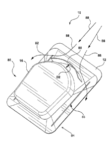
[0068] Referring to Figures 20, 21, shown is a further embodiment of the
roof
vent 10 showing the flange portion 12 to lay against the roof, the flange
portion 12
having an opening 22 (see Figure 22) to let air vent from the interior of the
building
(e.g. an attic). The roof vent 10 can optionally include a collar portion 14
extending
from the flange portion 12 and enclosing, at least in part, about a periphery
of the
opening 22, and a cap 16 dimensioned and configured to cover over the opening
22
(including the hole 28 in the roof) and optionally over the collar portion 14.
The cap 16
is configured to provide a passage (between the flange portion 12 and the cap
16)
through which air can pass between the atmosphere and the opening 22. The roof
vent 10 can also include a filter plate 46 (see Figure 14). Also included as
mounted
(e.g. either as a separate piece or moulded as an integral piece with the
flange portion
12) on the flange portion 12 is the shield 80, which can be arcuate in shape
as shown
in Figure 20 or other shapes such as linear as shown in Figure 25b. The shield
80 is
positioned in front of a leading edge 82 (positionable facing a ridge of the
roof) of the
roof vent 10 and also spaced apart therefrom. As shown, the shield 80 extends
from
the flange portion 12 and can be oriented as perpendicular with respect to the
flange
portion 12. Alternatively, the shield 80 can be oriented at an angle other
than 90
degrees with respect to the flange portion 12, e.g. generally transverse with
the flange
portion 12.
[0069] It is recognized that the shield 80 is integrated onto the common
flange
portion 12 with the roof vent 10 itself. It is important for the shield 80 and
the
frame/collar portion 14 to be integrated onto the common flange portion 12, as
the use
of a shared flange portion 12 (between the shield 80 and the frame/colar
portion 14)
CA 03063778 2019-11-15
WO 2018/209424 PCT/CA2018/000096
- 18 -
provides for a reduction in the number of auxiliary structures that must be
installed
(e.g. overlapped) with the roof cladding (e.g. shingles). As such, the
installation of the
shield 80 and the roof vent 10 itself can be accomplished via the mounting of
a single
flange portion 12 to the roof. As such, a predefined positioning of the shield
80
adjacent and spaced apart from the roof vent on the common flange portion 12
provides for an integrated shield 80 to be provided with and installed with
the roof vent
10. Further, it is advantageous for an installer to not have to measure or
otherwise
select the positioning of a separate shield on the roof with respect to the
roof vent 10
itself. It is recognized that positioning a separate shield (i.e. one not
mounted on the
flange portion 12 of the roof vent 10 but on the roof itself) too close to the
leading side
(i.e. oriented towards the peak) of the roof vent 10 can result in undesirable
blocking of
airflow for that side of the roof vent 10. Further, undesirable
accumulation/buildup of
snow/ice can occur between the roof vent 10 and the shield, if in the event
the
separate shield is positioned too close to the roof vent 10. Further, it is
recognized that
positioning of the separate shield too far from the side of the roof vent 10
(by the
installer) can result in water getting between the roof vent 10 and the
separate shield,
thereby making the separate shield ineffective for directing the running water
away
from the side of the roof vent 10.
[0070] As such, in view of the above, it is desirable and critical to have
the
shield 80 mounted on the flange portion 10 as an integrated shield 80
positioned a
predefined distance apart from the side of the roof vent 10 (i.e. from the
frame/collar
portion 14 positioned towards the roof peak), for those embodiments of the
roof vent
intended for placement on the roof in areas where running/voluminous water
streams can be expected.
[0071] Further, as shown in Figures 20 and 25b, the shield 80 can extend
from
one side 84 to the other side 86 of the roof vent 10, such the shield 80 can
be any of:
1) a length less than the width of the roof vent 10 between sides 84,86, 2) a
length
equal to the width of the roof vent 10 between the sides 84,86, or 3) a length
greater
than the width of the roof vent 10 between sides 84,86. As shown in Figure 20,
the
shield 80 deflects rain water 88 to either side 84,86 of the roof vent 10 as
the water
- 19 -
runs down the roof surface to which the roof vent 10 is mounted. It is
recognized that
the shield 80 can be shaped (curved or linear) similar to the shape of the
sidewall of the
cap portion 16, see Figures 20 and 25b. Alternatively, the shield 80 shape and
the cap
portion 16 shape can be different or dissimilar (e.g. linear for the shield 80
and curved
for the cap portion 16, curved for the shield 80 and linear for the cap
portion 16, etc.).
Further, the flange portion 12 can have ridges 85 upstanding from the flange
portion 12
adjacent to a periphery (e.g. sides 84,86) of the flange portion 12. The
ridges 85 can be
positioned on at least two sides 84,86 of the flange portion 12.
[0072] Referring to Figure 23, the distance D1 between the shield 80 and
the
frame/collar portion 14 is predefined, such that when the cap portion 16 is
positioned on
the frame/collar portion 14, the shield 80 is spaced apart by a predefined
distance D2
based on the extend of the cap portion 16 sidewalls (see Figure 20). As
discussed, the
provision of a predefined distance Dl ,D2 is important for those applications
in which an
integrated shield 80 on a common flange portion 12 along with the vent 10
(i.e.
collar/frame portion 14 with the cap 16) is desired.
[0073] Referring to Figures 22, 23 and 25b, the shield 80 can extend from
the
flange portion 12 by a height equal to a height of the roof vent 10 when fully
assembled
(e.g. with cap portion 16 thereon). Alternatively, the shield 80 can extend
from the
flange portion 12 by a height less than a height of the roof vent 10 when
fully
assembled. Alternatively, the shield 80 can extend from the flange portion 12
by a
height greater than a height of the roof vent 10 when fully assembled. For
example, as
shown in Figure 23, the shield 80 can extend from the flange portion 12 by a
height
greater than a height of the collar portion 14 of the roof vent 10.
Alternatively, the shield
80 can extend from the flange portion 12 by a height less than a height of the
collar
portion 14 of the roof vent 10. Alternatively, the shield 80 can extend from
the flange
portion 12 by a height equal to a height of the collar portion 14 of the roof
vent 10. In
any event, it is important that the extent(s) (side to side measurement and/or
height
measurement) is/are matched to the predefined distance D1,D2 as well as the
intended
mounting position of the roof vent 10 on the roof (in relation to the
slope/pitch and/or
distance from roof vent 10 to peak). As such, the anticipated amount of snow
and/or
Date Recue/Date Received 2022-06-01
- 1 9a -
running water volume can be anticipated base on distance from the apex/peak of
the
roof as well as the pitch/slope (rise/run) of the roof itself. For example, it
is
Date Recue/Date Received 2022-06-01
CA 03063778 2019-11-15
WO 2018/209424 PCT/CA2018/000096
- 20 -
anticipated that roofs of steeper pitch and/or longer distance between the
peak and the
roof vent 10 location will need taller and/or wider integrate shields 80 as
compared to
those roofs of shallower pitch and/or lesser distance from roof peak to
mounting
location of the roof vent 10.
[0074] As shown in Figures 24 and 25a, the roof vent 10 can have an outer
collar portion 14 and an inner collar portion 90, such that the inner collar
portion 90
and the outer collar portion 14 are spaced apart from one another and extend
from the
flange portion 12. It is recognized that the collar portion(s) 14,90 are
connected to the
flange portion 12 such that a base of the collar portion(s) 14,90 deflect
water from
entering the hole 22 in the flange portion 12, i.e. as water runs along the
roof and
between the cap portion 16 and the flange portion 12, the water is inhibited
from
entering the hole 22 by the upstanding collar potion(s) 14,90. As such, the
upstanding
collar portions are considered upstanding walls or vent deflectors to inhibit
water from
entering the hole 22 with or without presence of the shield 80 (i.e. the
shield when
integrated on the flange portion 12 provides enhanced water protection).
[0075] Further, it can be appreciated that for larger volumes of water
experienced by the roof vent 10, impinging on same as water runoff down the
roof
during storms, the optional shield 80 can provide for further inhibition of
water from
penetrating between the cap 16 and the flange portion 12, mounting the collar
portion(s) 14,90, and then entering the hole 22. As such, the shield 80 can be
used by
the roof vent 10 to deflect at least a portion if not all of the water runoff
from contacting
the collar portion(s) 14, 90, i.e. acting as a rain water deflector.
[0076] As such, in view of the above, it is recognized that in those
applications
where the integrated shield 80 is desired, the placement of the shield 80 on
the flange
portion 12 as an integrated shield 80 provides or numerous advantages, such as
more
efficient installation of the shielded vent 10 by the installer as compared to
having to
install a separate vent and shield in proximity to one another, potential
error in
placement of the separate shield in relation to the vent by the installer can
be negated
in the case of the integrated shield 80, ease of matching the roof vent 10
with
integrated shield 10 to the particular roof geometry (e.g. selected roof pitch
and
CA 03063778 2019-11-15
WO 2018/209424 PCT/CA2018/000096
- 21 -
distance from roof peak combination) via the integrated roof vent 10 and
shield 80
having a predefined distance D1,D2 and predefined shield 80 extent(s), and/or
ease of
installation with respect to installing of the roof vent 10 with integrated
shield 80 with
the roof cladding (e.g. overlapping of the shingles with the common flange
portion 12
of the roof vent 10 with shield 80).
[0077] It is also recognized that it can be disadvantageous to have a
separate
shield and roof vent, as the roof cladding material installation requirements
(e.g.
spacings between adjacent shingles, required nailing patters of the shingles,
etc.) may
not allow for proper placement of the separate shield with respect to the roof
vent (i.e.
adhering to preferred distances between the separate roof vent and shield for
adequate performance of the separate shield).
[0078] As such, it is recognized that the roof cladding (e.g. shingles)
for the roof
vent 10 with integrated shield 80 need not be positioned on top of the flange
portion 12
in between the shield 80 and the adjacent frame/collar portion 14. As such,
the roof
cladding need only be distributed about a periphery of the flange portion 12,
for
example such that the roof cladding overlaps on top of the opposed side edges
(between and connecting the top edge to the bottom edge) of the flange portion
12
and on top of the top edge of the flange portion 12 (e.g. nearest the roof
peak), while
traditionally the bottom edge (farthest from the roof peak) of the flange
portion 12 is
positioned over top of the roof cladding. The rest of the top surface (between
the side
edges and top and bottom edges) of the flange portion 12 can remain exposed
(i.e.
uncovered by roof cladding) as the roof flange portion 12 can be made out of a
weather resistant material such as plastic. Accordingly, the exposed top
surface
includes the top surface between the integrated shield 80 and the frame/collar
portion
14 adjacent and opposed to the integrated shield 80. The benefit of having an
exposed top surface of the flange portion 12, especially between the
integrated shield
80 and the frame/collar portion 14 adjacent and opposed to the integrated
shield 80, is
that precise roof cladding placement and resultant fastening (e.g. nails) of
the roof
cladding to the underlying roof sheathing between the integrated shield 80 and
the
CA 03063778 2019-11-15
WO 2018/209424 PCT/CA2018/000096
- 22 -
frame/collar portion 14 adjacent and opposed to the integrated shield 80 can
be
avoided.
[0079] Referring to Figures 26 and 27, alternative embodiments of the
filter 46
are provided as sheet (e.g. planar) filter portions having the perforations 47
without the
corrugations (i.e. creases) shown in Figures 6 and 7. As such, the
[0080] Referring to Figures 26 and 27 for the sheet filter 46 version (and
other
figures as appropriate for other portions of the roof vent 10), the filter
plate 46 can
have a pore size 47 (e.g. perforations, holes, a plurality of apertures, etc.)
sufficient to
facilitate air to pass through the filter material 46 (e.g. from one side 19
of the filter
material 46 to the other 19) but inhibit the passage of snow particles, cinder
particles
and/or water droplets there-through (e.g. from one side 19 of the filter
material 46 to
the other 19). In any event, it is recognized that the purpose of the filter
material 46 is
to provide for the flow through of air while inhibiting the passage of
undesirable
particles/droplets (e.g. solid and/or liquid pieces of matter) through the
corrugated filter
material 46 impinging from the atmosphere and into the interior of the roof
via the
opening 22 and adjacent hole 28.
[0081] For example, the filter material 46 can be positioned as extending
upwardly between the flange portion 12 and the cap 16 (covering the opening
22). It is
recognized that the filter material 46 can be in contact with a top surface 13
of the
flange portion 12, in contact with an underside surface 17 of the cap 16,
and/or in
contact with the top surface 13 of the flange portion 12 and with the
underside surface
17 of the cap 16. It is recognized that a sidewall 15 (e.g. collar wall ¨ see
Fig. 2)
extending upwardly from the top surface 13 of the flange portion 12 can also
be
considered as part of the top surface 13 of the flange portion 12. It is
recognized that
a sidewall (not shown) extending downwardly from the bottom/underside surface
17 of
the cap 16 can also be considered as part of the bottom/underside surface 17
of the
cap 16.
[0082] The sheet configuration of the filter 46 (see Fig. 26) can refer to
the
absence of draws or bends into folds or alternate furrows and ridges of the
surface of
the filter plate 46 seen in Figures 6 and 7. For example, the filter material
46 (e.g.
CA 03063778 2019-11-15
WO 2018/209424 PCT/CA2018/000096
- 23 -
plate) can be a single walled surface 19 as shown, can be a double walled
structure,
not shown, (e.g. having a space between adjacent walls having a sheet like
surface
19, etc). Preferably the filter material 46 has a sheet (e.g. planar, arcuate,
curved,
etc.) surface 19 exposed to the passage of air impinging on the filter
material 46 from
the atmosphere and directed towards the opening 22 (and overlapping hole 28 in
the
roof membrane of the building) and into the roof cavity (e.g. attic space).
Preferably
the filter material 46 has a sheet surface 19 exposed to the passage of air
impinging
on the filter material 46 from the exiting the roof cavity (e.g. attic space)
and directed
towards the opening 22 (and overlapping hole 28 in the roof membrane 50 of the
building) and into the atmosphere.
[0083] In terms of positioning of the filter material 46 with respect to
the cap 16
(at least covering the opening 28) and with respect to the flange portion 12,
the filter
material 46 can be positioned transverse to both of the cap 16 (e.g. underside
surface
17 of the cap 16) and the flange portion 12 (e.g. upper surface 13 of the
flange portion
12). As such, it is recognized that the filter material 46 can be in contact
with one of
the surfaces 13,17, with both of the surfaces 13, 17, an/or in contact with
none of the
surfaces 13,17 (e.g. suspended between the surfaces 13,17 by a secondary
structure
that can also be used to position the cap 16 in a spaced apart relationship
with the
flange portion 12. For example, the secondary structure can be provided by the
collar
portion 14 described herein as an example only. In any event, the filter
material 46
extends transversely (in whole, in part, etc.) between the cap 16 and the
flange portion
12 (e.g. base of the roof vent 10). In terms of in-whole, then any passage of
air
between the opening 22 and the atmosphere would pass though the body of the
filter
material 46. Alternatively, in terms of in- part, some of the passage of air
between the
opening 22 and the atmosphere would pass though the body of the filter
material 46
and passage of air between the opening 22 and the atmosphere would go around
the
body of the filter material 46. In terms of transverse, this can be referred
to as situated
or lying across (e.g. between the opposing surfaces 13,17), lying sideways
(e.g.
between the opposing surfaces 13,17), crosswise (e.g. between the opposing
surfaces
13,17), crossing from side to side (e.g. between the opposing surfaces 13,17),
athwart
(e.g. between the opposing surfaces 13,17), crossways (e.g. between the
opposing
CA 03063778 2019-11-15
WO 2018/209424 PCT/CA2018/000096
- 24 -
surfaces 13,17), lying or extending across or in a cross direction (e.g.
between the
opposing surfaces 13,17), cross (e.g. between the opposing surfaces 13,17).
One
example of transverse (e.g. between the opposing surfaces 13,17) can be lying
at right
angles to or perpendicular to each or both of the opposing surfaces 13,17). It
is also
recognized that the angle of the filter material 46, when extending away from
(either in
or out of contact with the actual surface 13,17) the surface 13,17, can be
other than 90
degrees, as desired.
[0084] In terms of the net free cross sectional area for the passage of
air
through the filter plate 46, the aggregate total open area (e.g. summation of
the
effective open area of each of the individual pore 47 cross sectional areas)
of the
plurality of holes/pores 47 can be configured to satisfy a minimum net open
area
threshold. For example, the open area threshold can be approximately 50 square
inches of flow ability (e.g. net free area) available for the passage of air
to flow
through. It is recognized that the minimum net open area threshold can be a
standard
defined threshold, different for each country, province, and/or state based
building
codes/standards. In an example where the filter plate 46 does not extend from
surface
13 to surface 17, the total net free air flow area available would be the
aggregate of
the effective open area of each of the individual pore 47 cross sectional
areas of the
filter plate 46 and the open cross sectional area of an air gap between an end
of the
filter plate 46 and the adjacent surface 13,17.
[0085] Referring to FIG. 1-27, the roof vent 10 provides for roof
ventilation while
at the same time inhibiting the infiltration of snow (e.g. undesired
particles) into the
attic. The roof vent 10 has the flange portion 12, optionally the collar
portion 14 (shown
as an example embodiment) and the cap 16 configured to cover over (e.g. most)
of the
collar portion 14 and to cover over a portion of the surface 19. Flange
portion 12 is
preferably flat to rest flush with the roof (not shown) to make it easy to
install the roof
vent. Collar portion 14 extends perpendicularly upward from flange 12. Cap 16
can
be dimensioned to enclose much of the collar portion 14 but to leave a space
gap 18
between the cap 16 and flange portion 12 to permit atmospheric air to pass
through
collar portion 14.
CA 03063778 2019-11-15
WO 2018/209424 PCT/CA2018/000096
- 25 -
[0086] It is also recognized that the frame portion 14 can be integrated
with the
filter material 46 (e.g. the frame portion 14 and the filter material 46 are
an integrated
component of the roof vent 10). For example, the frame portion 14 with
integrated
filter material 46 can be attached to both the cap 16 and the flange portion
12, such
that the frame portion 14 extends away (e.g. upwardly, downwardly, etc.) from
the
respective surfaces 13,17.
[0087] Referring again to Figures 26 and 27, as such, the sheet surface 19
can
have a similar surface area as compared to a corresponding planar surface of a
side
of the roof vent 10 (e.g. a planar cross sectional area of a bounded surface
measured
between an adjacent pair of support members 34 and the adjacent and opposing
surfaces 13,17). The filter plate 46 can have a pore 47 size which is selected
to inhibit
the passage of atmospheric particles (e.g. snow particles) through the filter
plate 46,
while facilitating the flow of air through the filter plate 46 from side 19 to
side 19. For
example, a pore size of approximately 120 microns can inhibit the passage of
snow
while providing for adequate air circulation through the non-corrugated
surface of the
filter plate 46. The material of the filter plate 46 can be composed of metal,
such as but
not limited to stainless steel, aluminum, or other materials that can inhibit
attachment
of the particles (e.g. snow) to the sheet/plate surface 19, when the surface
19 is in an
extending orientation (e.g. upwardly, away from, towards, etc.) with respect
to the
surface(s) 13,17.
[0088] As such, it is recognized that any of the roof vent 10 embodiments
shown in Figures 1-27 can have a corrugated version of the filter plate 46, a
non-
corrugated (e.g. sheet/plate) version of the filter plate 46, or a combination
(e.g. one or
more of the sides of the roof vent 10) can have different respective ones of
the
corrugated and the non-corrugated filters 46 (i.e. a mixture of corrugated and
non-
corrugated to provide for further inhibition of water penetration into the
hole 22). For
example, in terms of a mixture of filter types, the roof peak facing side of
the roof vent
could have a sheet configured filter plate 46 (of Figure 26) while the other
sides (i.e.
opposed side to the peak facing side and the sides there-between) could have
the
corrugated filter type (see Figure 6). For example, in terms of a mixture of
filter types,
CA 03063778 2019-11-15
WO 2018/209424 PCT/CA2018/000096
- 26 -
the roof peak facing side of the roof vent 10 could have a corrugated
configured filter
plate 46 (of Figure 6) while the other sides (i.e. opposed side to the peak
facing side
and the sides there-between) could have the non-corrugated filter type (see
Figure
26). It is
recognized that other alternative mixed type configurations are
contemplated.
100891 A
specific embodiment of the present invention has been disclosed;
however, several variations of the disclosed embodiment could be envisioned as
within the scope of this invention. It is to be understood that the present
invention is
not limited to the embodiments described above, but encompasses any and all
embodiments within the scope of the following claims.