Note: Descriptions are shown in the official language in which they were submitted.
CA 03063812 2019-11-15
1
METHOD FOR CREATING AN AIRCRAFT TURBOMACHINE VANE USING ADDITIVE
MANUFACTURING
TECHNICAL FIELD
This invention concerns a method for creating by additive manufacturing an
aircraft turbomachine vane, which may be part of an aircraft turbomachine
distributor or
rectifier sector.
BACKGROUND
The prior art comprises documents FR-A1-2 991 613, FR-A1-3 030 323, WO-Al-
2012/001324, US-A1-2004/031780 and FR-A1-3 002 167.
A turbomachine distributor sector comprises two circumferential walls, upper
and lower respectively, between which vanes extend comprising each a leading
edge and
a trailing edge extending between the walls. The leading edges of the vanes
are located
on the side of first circumferential edges of the walls and can be at least
partially retracted
with respect to these circumferential edges. Similarly, the trailing edges of
the vanes are
located on the side of the second circumferential edges of the walls and can
be at least
partially retracted with respect to these circumferential edges.
In the event that such a distributor sector is produced by additive
manufacturing,
by laser fusion on powder beds, the distributor would be produced on a support
plate so
that either the first circumferential edges or the second circumferential
edges will be
produced first directly on the support plate. In such a case, due to the above-
mentioned
retracting, there would be a gap between ail or part of the leading or
trailing edge of each
vane and the support plate. To avoid such gap, which could lead to subsidence
of the
material during manufacture, it would be possible to use temporary vane
support
members. These members would be produced simultaneously with the first or
second
edges, at the level of the vanes, and would extend between the support plate
and the
leading or trailing edges of the vanes.
However, these support members should be eliminated after manufacture. This
raises the question of their elimination, by the simplest possible technique,
without any
risk of damage to the vanes and of the distributor sector. A solution
consisting in using a
gripper to grasp each support member, disengaging it from the corresponding
vane by
. .
CA 03063812 2019-11-15
2
back and forth movement, then removing it with the gripper, would be possible.
However,
the operator's gesture would flot be precise and, because of the geometry of
the member
and its low stiffness, it could deform under the force applied by the gripper,
making it
more difficult to remove.
5 The invention
offers a simple, effective and economical solution to at least some
of these problems.
SUMMARY OF THE INVENTION
The invention proposes a method of creating at least one vane (i.e. any
10 aerodynamic
profile element) of an aircraft turbomachine, using additive manufacturing,
this vane comprising two circumferential walls, upper and lower respectively,
between
which extend at least one vane comprising each a leading edge and a trailing
edge
extending between said walls and at least partially retracted with respect to
first and
second circumferential edges of said walls, respectively, the method
comprising:
15 - an additive
manufacturing step by laser fusion on powder beds of said vane, the
manufacturing being carried out on a support plate so that said first or
second
circumferential edges are manufactured first directly on said support plate,
at least one
temporary support member being produced simultaneously with said first or
second
edges, at the level of said or each vane, and extending between said support
plate and
20 said leading or trailing edges of the vane, and
- a step of removing said or each supporting member by breaking its connection
with the associated leading or trailing edge,
characterized in that the removing is carried out by means of a tool, at least
one
end of which is engaged in at least one recess of said or each supporting
member, and
25 which is moved
by pivoting in a plane substantially perpendicular to the associated leading
or trailing edge.
The invention can be applied to a single vane, i.e. isolated, or a series of
vanes
forming a monoblock assembly called a sector. The sector can be a rectifier
sector (for a
compressor) or a distributor sector (for a turbine).
30 The invention
allows to solve the above-mentioned problem. It allows to stiffen
the support member but also to make its removal operation easier, faster and
also less
constraining for the operator. One of the problems was the lack of rigidity,
as the walls of
. .
CA 03063812 2019-11-15
3
the member could coliapse under the action of the gripper. The presence and
conformation of the recess allow to simplify the shape of the member, which is
thus
stiffened.
The process according to the invention may comprise one or more of the
5 following
characteristics or steps, taken in isolation from or in combination with each
other:
- said tool is a screwdriver, preferably a flat end or head,
- each member comprises one to th ree recesses or more. The nunnber of
recesses
depends, for example, on the contact surface between the support member and
the vane,
10 - each member
may comprise a main recess and two secondary recesses arranged
on two opposite sides of the main recess,
- said main recess is delimited by walls thicker than those delimiting the
secondary
recesses; this allows the member to have sufficient strength when a removal
force is
applied,
15 - the method is
applied to a series of vanes belonging to the same distributor or
rectifier sector.
The present invention also concerns an aircraft turbomachine vane produced by
the method described above, said vane comprising two circumferential walls,
upper and
lower respectively, between which extend at least one vane comprising each a
leading
20 edge and a
trailing edge extending between said walls and at least partially retracted
with
respect to first and second circumferential edges of said walls respectively,
at least one
temporary support member being located at the level of the leading or trailing
edge of
said or each vane, and extending between a plane passing through said first or
second
edges and said leading or trailing edge of said or each vane, characterized in
that said or
25 each support
member comprises at least one recess configured to receive at least one
end of a tool, for pivoting removal of said member.
The vane according to the invention may comprise one or more of the following
characteristics or steps, taken in isolation from each other or in combination
with each
other:
30 - each member comprises one to three or recesses or more,
- the or each recess is delimited by transverse reinforcing walls,
. .
CA 03063812 2019-11-15
4
- each member has a thickness that varies between one end located on the side
of the lower wall and an opposite end located on the side of the upper wall,
- each member comprises at least one lightening cavity; this type of cavity
can
also reduce the melting time and the powder consumption during the additive
5 manufacturing,
- each lightening cavity is delimited by side walls of the member which
comprise
lightening notches,
- said lightening notches each have a general V-shape; this configuration can
allow
to facilitate the removal of powder from the cavities during a de-powdering
operation at
10 the end of the
additive manufacturing operation; it can also allow to reduce the melting
time and the powder consumption.
DESCRIPTION OF THE FIGURES
The invention will be better understood and other details, characteristics and
15 advantages of
the invention will appear more clearly when reading the following
description made by way of non-limiting example and by reference to the
annexed
drawings in which
- Figure 1 is a very schematic view of a facility for the additive
manufacturing of a
compressor rectifier sector,
20 - Figure 2 is a
schematic perspective view of a rectifier sector produced by additive
manufacturing, the rectifier being in conformity with the invention,
- Figure 3 is a larger scale view of part of the rectifier sector of Figure 2,
- Figures 4a to 4d are schematic views in perspective of a rectifier sector
and
illustrate a manual step of removing the rectifier support members, and
25 - Figure 5 is a
view corresponding to Figure 3 and representing a variant of
embodiment of the invention.
DETAILED DESCRIPTION
Figure 1 shows an installation for creating a rectifier sector by additive
30 manufacturing,
and in particular by selective fusion of powder beds via a high energy
beam, such as a laser beam.
. .
CA 03063812 2019-11-15
The machine comprises a feeder tray 170 containing powder of a material such
as a metal alloy, a roller 130 to transfer this powder from this tray 170 and
spread a first
layer 110 of this powder on a construction support tray 180.
The machine also includes a recycling tray 140 to recover the used powder
5 (especially unfused or unsintered powder) and the excess powder (mostly),
after
spreading the powder layer on the support plate 180. Thus, most of the powder
in the
recycling tray is new powder. Also, this recycling tray 140 is commonly
referred to by the
profession as an overflow tray or ashtray.
This machine also comprises a generator 190 of energy beam (e.g. laser) 195,
and
10 a control system 150 capable of directing this beam 195 on any region of
the support plate
180 so as to scan any region with a powder layer. The shaping of the energy
beam (laser)
and the variation of its diameter on the focal plane are done respectively by
means of a
beam dilator 152 and a focusing system 154, the whole constituting the optical
system.
This machine to apply the method assimilable to a Direct Metal Deposition
(DMD)
15 method to a powder can use any high-energy beam instead of the laser
beam 195, as long
as this beam is energetic enough to in the first case meit or in the other
case form collars
or bridges between the powder particles and a part of the material on which
the particles
rest.
The roller 130 can be replaced by another suitable dispensing system, such as
a
20 dispenser (or hopper) associated with a wiper blade, a knife or a brush,
capable of
transferring and spreading the powder in a layer.
The control system 150 comprises, for example, at least one steerable mirror
155
on which the laser beam 195 is reflected before reaching a powder layer whose
each point
of the surface is always located at the same height with respect to the
focusing lens,
25 contained in the focusing system 154, the angular position of this
mirror 155 being
controlled by a galvanometric head so that the laser beam scans at least a
region of the
first powder layer, and thus follows a pre-established part profile.
This machine works as follows. A first layer 110 of powder of a material is
applied
to the support plate 180 with the aid of the roller 130, this powder being
transferred from
30 a feeder tray 170 during a forward movement of the roller 130 and then
wiped, and
possibly slightly compacted, during one (or more) return movement (s) of the
roller 130.
The excess powder is recovered in the recycling tray 140. A region of this
first layer 110 of
. .
CA 03063812 2019-11-15
6
powder is scanned with the laser beam 195 to a temperature higher than the
melting
temperature of this powder (liquidus temperature). The galvanometric head is
controlled
according to the information contained in the database of the computer tool
used for the
computer-aided design and manufacture of the part to be manufactured. Thus,
the
5 powder particles 160 of this region of the first layer 110 are melted and
form a first cord
115 in one piece, integral with the support plate 180. At this stage, several
regions
independent of this first layer can also be scanned with the laser beam to
form, after
melting and solidifying the material, several first cords 115 separated from
each other.
The support plate 180 is lowered by a height corresponding to the already
defined
10 thickness of the first layer (between 20 and 100 ilm and generally by 30
to 50 lm). The
thickness of the powder layer to be melted or consolidated remains a variable
value from
one layer to another because it is highly dependent on the porosity of the
powder bed
and its flatness, while the pre-programmed displacement of the support plate
180 is a
value that cannot change except for the clearance. A second layer 120 of
powder is then
15 applied to the first layer 110 and to this first cord 115, and then a
region of the second
layer 120 which is partially or completely located above this first cord 115
is heated by
exposure to the laser beam 195, so that the powder particles of this region of
the second
layer 120 are melted, with at least part of the first cord 115, and form a
second cord in
one piece or consolidated 125, all of these two cords 115 and 125 forming a
block in one
20 piece. For this purpose, the second cord 125 is advantageously already
fully bound as soon
as part of this second cord 125 binds to the first member 115. It is
understood that
depending on the profile of the part to be constructed, and in particular in
the case of an
undercut surface, the above-mentioned region of the first layer 110 may flot
lie, even
partially, below the above-mentioned region of the second layer 120, so that
in this case
25 the first cord 115 and the second cord 125 do not form a block in one
piece. This process
of building the part layer by layer is then continued by adding additional
layers of powder
on the already formed assembly. The scanning with the beam 195 allows each
layer to be
constructed by giving it a shape in accordance with the geometry of the part
to be
produced, for example the above-mentioned lattice structures. The lower layers
of the
30 part cool more or less quickly as the upper layers bf the part are
built.
In order to reduce the contamination of the part, for example in dissolved
oxygen,
oxide(s) or another pollutant during its manufacturing layer by layer as
described above,
. .
CA 03063812 2019-11-15
7
this manufacture must be carried out in an enclosure with a controlled degree
of
hygrometry and adapted to the method / material combination, filled with a
neutral gas
(non-reactive) against the material under consideration such as nitrogen (N2),
argon (Ar)
or helium (He) with or without the addition of a small quantity of hydrogen
(112) known
5 for its reducing power. A mixture of at least two of these gases can also
be considered. To
prevent contamination, particularly by oxygen from the surrounding
environment, it is
customary to overpressure this enclosure.
Thus, selective fusion or selective laser sintering allows to build low-
polluted parts
with good dimensional accuracy, whose three-dimensional geometry can be
complex.
10 Selective fusion or selective laser sintering also preferably uses
powders of
spherical morphology, clean (i.e. not contaminated by residual members from
synthesis),
very fine (the size of each particle is between 1 and 100 lm and preferably
between 45
and 90 'lm), which allows to obtain an excellent surface finish of the
finished part.
Selective melting or selective laser sintering also reduces manufacturing
times,
15 costs and fixed costs compared to a part cast, injected or machined in
the mass.
The invention uses additive manufacturing by laser fusion on powder beds to
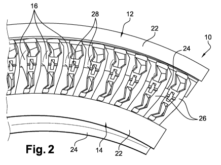
produce a turbomachine rectifier sector 10. Figure 2 shows an embodiment of
the
invention. This rectifier sector 10 comprises two circumferential walls,
respectively upper
20 12 and lower 14, between which extend vanes 16 each having a leading
edge 18 and a
trailing edge 20 extending between walls 12, 14 and at least partially
retracted with
respect to first and second circumferential edges 22, 24 of these walls
respectively.
Temporary support members 26 are located at the level of the leading edges 18
or trailing
edges 20 of the 16 vanes, and extend between a plane passing through the first
or second
25 edges 22, 24 and the leading edges 18 or trailing edges 20 of the vanes.
As shown in the
drawings, each of the support members 26 comprises at least one recess 28
configured
to receive at least one end of a tool 30 such as the free end of a flat
screwdriver, for the
pivoting remova I of this member 26.
In the example of embodiment of figures 2 to 4d, the member 26 comprises a
30 recess 28 but it could include several, such as three in the embodiment
variant of figure 5.
CA 03063812 2019-11-15
8
Each member 26 is elongated in shape and extends longitudinally between watts
12, 14. In the example shown, its transverse thickness, located on the side of
the upper
watt 12, is larger than that of its lower end, located on the skie of the
lower wall 14.
Each member 26 comprises an elongated bottom watt 26a extending in a plane
substantially parallel to the edges 22, 24, and connected to peripheral watts
26b, 26c, 26d
substantially perpendicular to the bottom watt 26a. The upper watt 26b is
located on the
side of the upper wall 12, the lower watt 26d is located on the side of the
lower watt 14,
and the side watts 26c extend distance from each other, between the watts 12
and 14.
The recess 28 is located substantially in the middle of the member 26 and is
delimited by the side watts 26c on the one hand, and by two transverse
reinforcing watts
26e on the other hand. Each recess 28 has an elongated shape, along the
elongation axis
of the member, and is shaped to receive the tip of tool 30. Between the recess
28 and the
watts 26b, 26d, the member comprises, between the watts 26c, lightening
cavities 32. The
watts 26c include, at the level of these cavities 32, lightening notches 34.
These notches
have a general V-shape here.
The portions of watts 26c delimiting the recesses 28 are over-thick compared
to
the rest of these watts. In addition, these watt portions 26c comprise
transverse notches
33 configured to facilitate the de-powdering, i.e. the removal of the powder
located in
the recess 28 at the end of the additive manufacturing operation. The watts
26e are also
over-thick, particularly compared to the above-mentioned rest of the walls
26c.
ln the event that the first edges 22, such as the downstream edges (by
reference
to the flow of gases in the turbomachine), are made first during the additive
manufacturing, it is understood that the downstream face of the rectifier
would be the
lower face that would be in contact with the support plate 180 in Figure 1.
The trailing
edges of the vanes would be oriented towards the support plate 180.
In this case, the support members 26 are made simultaneously with the edges
22,
by additive manufacturing, and ensure the support of the vanes 16 to avoid
their collapse.
They are thus intended to extend between the plate 180 and the trailing edges
of the
vanes in the example shown. They are supported here by the walls 26b, 26c, 26d
on the
support plate 180, and connected by continuity of material to the vanes 16, by
their watts
26a.
CA 03063812 2019-11-15
9
According to the invention, the removal of each support member 26 is carried
out
by means of tool 30, at least one end of which is engaged in the recess of
each of the
support members 26, and which is pivoted in a plane substantially
perpendicular to the
associated leading (or trailing) edge.
Figures 4a to 4d illustrate steps for removing a last member 26 from a
rectifier
sector 10, the other members having already been removed. The tip of the tool
30 is
inserted into the recess 28 of the member 26 (figure 4a), then the tool 30 is
pivoted in the
above-mentioned plane until the material breaks between the trailing edge of
the vane
and the member 26 (figures 4b and 4c). The member is pivoted and lifted by the
tool away
from the vane and out of the space between the walls 12, 14 of the rectifier
sector.
With the invention, the risk of deformation of the member 26 is limited. In
addition, the removal operation is facilitated because it is quick and
repeatable due to the
precise positioning of the tool in the member.
In the particular case of the variant in Figure 5, the member 26 comprises
three
recesses 28 aligned in the same parallel plane with the axis of elongation of
the member,
and the tool for removing this type of member may have three ends or tips to
be inserted
into the recesses of the member respectively. This allows the removal forces
of the
member to be distributed over its length.
Although the invention has been illustrated with reference to a rectifier
sector, it
applies to a distributor sector. In the example shown, the sector includes
several vanes.
Alternatively, it could comprise only one, this single vane forming a vane
with the walls
12 and 14. In other words, the invention is applicable to a single vane or to
a sector, i.e.
to any monobloc assembly comprising walls 12, 14 between which one or more
vanes 16
extend.