Note: Descriptions are shown in the official language in which they were submitted.
CA 03063996 2019-11-18
PCT/EP2018/064064 - 1 -
2017P00175WO
Specification
Device for guiding metal strips with wearing bodies in a
finishing train
Technical field
The present invention relates to a device for laterally guiding
a metal strip that by way of different paths runs across a loop
lifter that is adjustable to various positions between two roll
stands of a finishing train.
Prior art
In the production of metal strips the latter after rolling in a
reversing stand in a finishing train are continuously rolled in
a plurality of roll stands and by means of roller tables with
laminar cooling are directed to coiling devices where said
metal strips are coiled. In the finishing train it is necessary
for the metal strips to be subjected to lateral guiding in
order for a centric infeed to the roll gap of the roll stands
to be performed. Devices for lateral guiding are referred to as
guide rulers. The edges of the running metal strip on which the
devices for lateral guiding act cause wear on the wear strips
which are fastened to the guide rulers, or on the wear faces of
said wear strips, respectively. In the case of certain material
qualities, the strip edges are abraded. The abraded material
can adhere to the guide rulers and generate so-called packs of
deposits. Should the latter drop onto the metal strip, this can
lead to surface defects on the metal strip. Therefore, the wear
faces of the wear strips have to be regularly refurbished and
cleaned, depending on the production schedule.
CA 03063996 2019-11-18
PCT/EP2018/064064 - 2 -
2017P00175W0
In order for the complexity to be minimized, it is known that
not always the entire wear strips of the guide rulers are
replaced when refurbishing. For example, it is described in
W02015043926A1, the disclosure of the latter being incorporated
in the disclosure of the present application, that rotatable
wear members which guide the metal strip are also present in a
main member module having a guiding plane. According to
W02015043926A1, the wear members in a controlled manner are
rotatable to a plurality of defined rotary positions. Once a
first metal strip has passed through the metal strip conveyor
device, and before a second metal strip runs into the metal
strip conveyor device, the wear members in a controlled manner
are rotated from a first defined rotary position to a second
defined rotary position. The second metal strip does not run
through the wear rut cut into the wear face of the wear member
by the first metal strip. Instead, said second metal strip is
guided through a region of the wear face that is exposed to a
metal strip for the first time, and therein steadily cuts a new
wear rut.
The length of the metal strip is modified when rolling in the
finishing train. So-called loop lifters for regulating the
strip tension in a simpler manner, or for maintaining the
tension of said strip despite the modification in terms of
length, respectively, are installed between the roll stands in
the finishing train. This herein is substantially a roller, the
horizontal rotation axis thereof being vertically adjustable.
The metal strip is tensioned and guided by way of the loop
lifter roller, also referred to as the looper roller, when the
surface of said loop lifter roller is above the pass line of
the finishing train. In order for a metal strip that has been
elongated and accelerated by rolls to be kept tensioned, the
loop lifter roller is moved upward out of the pass line as a
function of the force generated by the metal strip and acting
on the loop lifter roller. The farther the rotation axis of the
CA 03063996 2019-11-18
PCT/EP2018/064064 - 3 -
2017P00175W0
loop lifter roller is above the pass line, the greater the
strip infeed angle into the following roll gap, or the strip
outfeed angle from the previous roll gap, the metal strip
having in each case another path between the two roll gaps.
There should be lateral guiding of the metal strip at each
strip infeed angle, or strip outfeed angle, or for each path,
respectively.
A replacement or manual cleaning of the guiding wear faces in
the region of the loop lifters is very complex and dangerous
since there is little available space in the region of the
stand and high temperatures prevail on account of rolling the
metal strip at a temperature of approx. 1100 C. Such activities
can consequently only take place during stoppages of the
finishing train.
Summary of the invention
Technical object
It is the object of the present invention to propose a
finishing train, devices, and a method for operating the
devices in which in the case of lateral guiding of a metal
strip that in a finishing train is guided by way of loop
lifters the complexity and the frequency of the requirement of
replacing worn parts, or cleaning of wear faces, respectively,
is minimized in the case of each strip infeed angle or strip
outfeed angle, respectively.
Technical achievement
This object is achieved by a finishing train having at least
two roll stands and at least one loop lifter which is disposed
CA 03063996 2019-11-18
PCT/EP2018/064064 - 4 -
2017P00175W0
between two neighboring roll stands and is adjustable to
various positions,
and having at least one device for laterally guiding a metal
strip that by way of different paths runs by way of the loop
lifter between two roll stands,
said device for lateral guiding comprising at least one main
member module having a substantially vertical guiding plane,
and a plurality of wear members which are rotatable to a
plurality of rotary positions and which have a wear face,
wherein the wear faces of the wear members are substantially
planar and in all rotary positions are substantially parallel
to the guiding plane,
characterized in that
at least two wear members are in each case disposed between one
of the roll stands and the loop lifter,
wherein the area of the wear face of neighboring wear members
increases when viewed in the direction of the loop lifter.
The finishing train has at least two roll stands. At least one
loop lifter is disposed between two neighboring roll stands,
when viewed in the running direction of the strip. When there
are more than two roll stands, at least one loop lifter can
also be repeatedly present between two neighboring roll stands.
Neighboring herein is to be understood to mean closest. For
example, when three roll stands A, B, C are present, one loop
lifter can be present between the neighbors A and B, and one
loop lifter can be present between the neighbors B and C. When
viewed in the running direction of the strip, A and B are
neighbors and B and C are neighbors, but A and C are not
neighbors.
At least one device for lateral guiding is present in the
finishing train; said device guides the metal strip that runs
by way of the loop lifter between the two neighboring roll
stands. In the device for lateral guiding, which has in each
CA 03063996 2019-11-18
PCT/EP2018/064064 - 5 -
2017P00175W0
case at least two wear members between one of the two
neighboring roll stands and the loop lifter between said two
neighboring roll stands, the area of the wear face of
neighboring wear members increases from one wear member to
another wear member, when viewed in the direction of the loop
lifter. In other words, in the case of neighboring wear members
the wear face in the case of that wear member that is situated
closer to the loop lifter is larger than in the case of the
wear member which is more remote from the loop lifter.
Neighboring herein is to be understood to mean closest.
The metal strip is a steel strip or an aluminum strip, for
example.
The main member module having a guiding plane is, for example,
a so-called guide ruler which has a face suitable for guiding
the metal strip, said face being the guiding plane. Said
guiding plane can be formed by one, or a plurality, of wear
plate(s) fastened to a support member; the support member and
the wear plate(s) in this instance conjointly form the main
member module. The device for lateral guiding can comprise one
main member module or a plurality of main member modules. For
example two main member modules, one each for guiding one side
of the metal strip. The guiding plane serves for laterally
guiding the metal strip by means of contact with the sides of
the metal strip. Said guiding plane restricts the freedom of
movement of the metal strip in the direction of said guiding
plane, on account of which the metal strip is laterally guided.
The guiding plane is aligned so as to be substantially
vertical.
Apart from the main member module, the device for lateral
guiding additionally also comprises a plurality of wear members
having a wear face. A wear member is a member which as a result
of guiding the metal strip is subjected to wear, specifically
CA 03063996 2019-11-18
PCT/EP2018/064064 - 6 -
2017P00175WO
in a region which is referred to as the wear face. The wear
member is a component other than the main member module, but
can be inserted in the main member module or be fastened
thereto, respectively. The wear member possesses at least one
wear face; said wear face when guiding the metal strip faces
the metal strip and in the course of laterally guiding the
metal strip wears on account of contact with the metal strip.
The metal strip cuts into the wear member and thus causes wear
on the latter.
The wear face in the non-worn state is substantially planar.
The wear face is the region of the wear member that in
operation is provided for guiding the metal strip. This can be
a face before said face is used for guiding and becomes worn.
This can also be a face which has already been abraded on
account of wear that has previously taken place and is again
used for guiding. Of course, the so-called wear member can also
have regions which in operation do not come into contact with
the metal strip, for example by virtue of the distance of said
regions from the pass line of the finishing train.
The wording "substantially" is to imply that minor deviations
from the required properties of planar, vertical, parallel, are
acceptable. For example, deviations in relation to parallel or
vertical, respectively, of up to 50, preferably of up to 2 .
The wear member can be round or have other contours.
The wear member is rotatable to a plurality of rotary
positions. Said wear member can thus assume at least two rotary
positions, the operator being able to choose between said
rotary positions and to correspondingly control the rotation in
an open-loop and/or closed-loop manner. This herein includes
that the wear member successively assumes a multiplicity of
rotary positions while said wear member is rotated. The wear
CA 03063996 2019-11-18
PCT/EP2018/064064 - 7 -
2017P00175WO
member can be fixed in a desired rotary position which said
wear member has reached by rotation, or else be rotated to a
further rotary position by further rotation. The rotation
herein can also be performed very slowly, for example with one
revolution in 12 hours; a multiplicity of rotary positions are
successively assumed in the 12 hours.
A loop lifter is present between two roll stands of the
finishing train. At least two wear members are provided between
a roll stand and the loop lifter in the device for lateral
guiding.
The area of the wear face of neighboring wear members increases
in the direction of the loop lifter. For example, if three wear
members are disposed between a roll stand and a loop lifter
that follows in the running direction of the strip, the wear
member that directly neighbors the roll stand has the smallest
area of the three wear members, and the wear member that
directly neighbors the loop lifter has the largest area. The
central wear member has a larger area than its neighbor that
directly neighbors the roll stand, and has a smaller area than
its neighbor that directly neighbors the loop lifter. Should
these be round wear members, the wear member directly
neighboring the roll stand will thus have the smallest
diameter, the wear member directly neighboring the loop lifter
will have the largest diameter, and the wear member disposed
therebetween will have an intermediate diameter.
The loop lifter, for example controlled in a closed-loop manner
by pressure or force, is adjustable to various positions and in
the operation of the finishing train is situated in various
positions, depending on the properties of the metal strip. For
each position of the loop lifter another path results for the
metal strip between a roll stand and the directly neighboring
loop lifter; the strip infeed angle and the strip outfeed
CA 03063996 2019-11-18
PCT/EP2018/064064 - 8 -
2017P00175W0
angle, respectively, are in each case different. The strip
infeed angle and the strip outfeed angle, respectively, refer
to the plane in which the roll gaps of the two roll stands lie;
the metal strip exits the roll gap of the first roll stand
(when viewed in the running direction of the strip), and runs
its path in the direction of the closest stand by way of the
loop lifter roller where said metal strip is deflected. From
there, said metal strip runs into the roll gap of the second
roll stand (when viewed in the running direction of the strip).
Advantageous effects of the invention
A wear member is rotatable about a rotation axis. The rotation
axis is preferably perpendicular to the wear face. The wear
member is, particularly preferably, a round disk having a
planar wear face which is formed by the base area of the disk.
In order to prevent that the wear of a region of the wear face
of the wear member exceeds an acceptable level, the wear member
can be rotated about the rotation axis on account of which
another region brought to face the edge of the metal strip and
as a result of guiding the metal strip is worn down by said
edge. The requirement for replacing the wear face, or the wear
member, respectively, can be delayed by multiple rotation,
since other regions are continuously brought to face the edge
of the metal strip and the wear is therefore distributed
uniformly across the wear face. The complexity for replacing
worn parts is thus reduced since a replacement is required less
frequently. Moreover, it can also be ensured that so-called
packs of deposits do not accumulate at one location.
Accordingly, the risk of said deposits dropping onto the metal
strip is minimized. Moreover, existing packs of deposits can
optionally also be abraded from the metal strip again at
another rotary position of the wear member.
CA 03063996 2019-11-18
PCT/EP2018/064064 - 9 -
2017P00175WO
From the roll stand in the direction of the loop lifter, the
metal strip moves ever further away from the pass line of the
finishing train. Another infeed angle and outfeed angle and
thus another path results for each position of the loop lifter.
In one finishing train according to the invention, or by way of
the device according to the invention, respectively, lateral
guiding by way of wear plates is possible at each angle between
the pass line of the finishing train and the metal strip. This
is enabled in that the wear plates have larger areas as the
proximity to the loop lifter increases, and thus can also
provide lateral guiding as the distance of the metal strip from
the pass line increases. The wear members are preferably
replaceable such that said components can be simply replaced in
the event of excessive wear. A replacement of the main member
modules, or of parts of the main member modules, respectively,
such as wear plates, for example that is comparatively more
complex is required less frequently since the lateral guiding
on account of only the wear members is also sufficient. Since
the wear members can be rotated to various rotary positions, a
new region of the wear faces can be worn out again at all
times, on account of which the wear can be distributed and a
replacement is required less frequently. This saves complexity
and costs in terms of the maintenance of the device for lateral
guiding.
According to one preferred embodiment, at least one wear member
is capable of being disposed in a recess of the at least one
main member module. When the at least one wear member is
disposed in a recess of the at least one main member module it
is possible for simultaneous guiding of the metal strip to be
performed by the main member module and the wear member, for
example when the wear face of the wear member does not protrude
beyond the guiding plane of the main member module but at least
CA 03063996 2019-11-18
PCT/EP2018/064064 - 10 -
2017P00175W0
in part lies in said guiding plane. This may be the case when
the wear face is substantially planar, as is required according
to the invention, and lies parallel to the guiding plane, as
parallel to the guiding plane also includes being in one plane
with the guiding plane. Or when the wear face of the wear
member does not protrude beyond the guiding plane of the main
member module and does not lie in said guiding plane but is
further remote from the metal strip than the guiding plane of
the main member module, specifically when the metal strip cuts
so far into the main member module that said metal strip also
comes into contact with the wear face and is guided on account
thereof.
The recess is preferably round. This enables simple rotating of
a wear member that is disposed in said recess when said recess
is rotationally symmetrical in relation to the rotation axis of
said wear member. When the recess is not completely enclosed by
the main member module, the periphery of the recess in the main
member module in this embodiment follows part of a circle. The
recess can also have other shapes.
Variants pertaining to the embodiment of wear members which can
optionally also be applied in the device according to the
invention for lateral guiding of a metal strip that runs across
a metal strip conveying device in a finishing train comprising
at least one main member module having a substantially vertical
guiding plane are to be derived from W02015043926A1, the
disclosure of the latter being incorporated in the disclosure
of the present application.
The wear members in the finishing train according to the
invention are preferably disposed such that each path leads
across each wear face. It thus applies to each path that said
path in part lies on each of the wear plates between the roll
stand and the loop lifter; all wear members in this instance
CA 03063996 2019-11-18
PCT/EP2018/064064 - 11 -
2017P00175W0
contributing to the lateral guiding independently of the
spacing between the loop lifter roller and the pass line.
A further subject matter of the present invention is a device
for laterally guiding a metal strip that by way of different
paths runs across a loop lifter that is adjustable to various
positions between two roll stands of a finishing train,
comprising at least one main member module having a
substantially vertical guiding plane, ,
and a plurality of wear members which are rotatable to a
plurality of rotary positions and which have a wear face,
wherein the wear faces of the wear members are substantially
planar and in all rotary positions are substantially parallel
to the guiding plane,
characterized in that
at least two wear members are disposed in at least one main
member module, wherein the areas of the wear faces of
neighboring wear members are of dissimilar sizes.
Such a device can be installed, for example, in a conventional
finishing train such that a finishing train according to the
invention is created. Or said device can be installed in a
finishing train according to the invention so as to replace an
already existing device according to the invention, or so as to
increase the existing number of devices according to the
invention in the finishing train.
In a device according to the invention it is preferable that
the area of the wear face of directly neighboring wear members
in a main member module, when viewed in the direction of a
longitudinal extent of the main member module, increases from
one wear member to another wear member.
A longitudinal extent of the main member module in the
installed state between a roll stand and loop lifter for the
CA 03063996 2019-11-18
PCT/EP2018/064064 - 12 -
2017P00175W0
operation in a finishing train is to be viewed from the loop
lifter in the direction of the roll stand, or from the roll
stand in the direction of the loop lifter, respectively, thus
in the direction or counter to the direction in which the metal
strip to be laterally guided in operation runs through the
finishing train.
The effects pertaining to the finishing train already set forth
above are derived.
The wear members in the device according to the invention are
preferably disposed such that each path leads across each wear
face. It thus applies to each path that said path in part lies
on each of the wear plates between the roll stand and the loop
lifter; all wear members in this instance contributing to the
lateral guiding independently of the spacing between the loop
lifter roller and the pass line.
In other words, a device according to the invention for
laterally guiding a metal strip that in the operation in a
finishing train by way of different paths runs across a loop
lifter that is adjustable to various positions between two roll
stands of a finishing train comprises
at least one main member module having a substantially vertical
guiding plane, and a plurality of wear members which are
rotatable to a plurality of rotary positions and which have a
wear face, wherein the wear faces of the wear members are
substantially planar and in all rotary positions are
substantially parallel to the guiding plane,
wherein at least two wear members are in each case disposed
between one of the roll stands and the loop lifter,
wherein the area of the wear face of neighboring wear members
increases when viewed in the direction of the loop lifter,
the wear members (18, 19, 20) herein being preferably disposed
such that each path leads across each wear face (21, 22, 23).
CA 03063996 2019-11-18
PCT/EP2018/064064 - 13 -
2017P00175W0
Said device according to the invention is suitable for lateral
guiding in a finishing train as claimed in claim 1 or 2.
A further subject matter of the present invention is a method
for operating a finishing train according to the invention or a
device according to the invention for lateral guiding,
characterized in that
at least one of the wear members is rotated while the metal
strip is running.
Said at least one wear member assumes a multiplicity of rotary
positions during the rotation. The rotation herein can also be
performed very slowly, for example by one revolution in 12
hours. The rotation can also be interrupted by intervals. On
account of the rotation, the wear of the wear members can be
distributed uniformly across the wear face, this aiding in
extending the replacement intervals. The rotation can be
performed to defined rotary positions, as in W02015043926A1;
said rotation can also be performed to non-defined rotary
positions in terms of the rotation axis in the sense that it is
not predetermined by the operator that a specific rotary
position is to be assumed at a specific point in time.
A different path of the metal strip results for each position
of the loop lifter. The path followed by the metal strip is
different, depending on the position of the loop lifter.
Rotating takes place while the metal strip is running,
preferably while lateral guiding by the rotated wear member is
performed.
Lateral guiding by each wear member is preferably performed on
each path. It thus applies to each path that said path in part
lies on each of the wear faces between the roll stand and the
loop lifter; all wear members in this instance contributing to
CA 03063996 2019-11-18
PCT/EP2018/064064 - 14 -
2017P00175W0
the lateral guiding independently of the spacing between the
loop lifter roller and the pass line.
Brief description of the drawings
The present invention will be described in an exemplary manner
hereunder by means of schematic figures in which:
fig. 1 schematically shows a conventional device for laterally
guiding a metal strip running across a loop lifter
between two roll stands of a finishing train; and
fig. 2 schematically shows an embodiment of a device according
to the invention as said device is in operation when
installed in a finishing train according to the
invention.
Description of the embodiments
Exemplars
Fig. 1 in a lateral view shows in fragments how a metal strip 1
in the direction indicated by an arrow runs across a loop
lifter 4 between two roll stands 2, 3 of a finishing train in a
conventional device. Plate-shaped wear strips 5a, 5b are
present to the right and the left of the loop lifter 4 in order
for the running metal strip 1 to be laterally guided. The loop
lifter 4 is adjustable to various positions, this being
illustrated by a double arrow. Depending on the position, the
metal strip 1 follows a different path from the roll gap 6 of
the first roll stand 2 in the running direction of the strip
into the roll gap 7 of the second roll stand 3 in the running
CA 03063996 2019-11-18
PCT/EP2018/064064 - 15 -
2017P00175W0
direction of the strip. Only the path associated with the
illustrated position of the loop lifter 4 is illustrated.
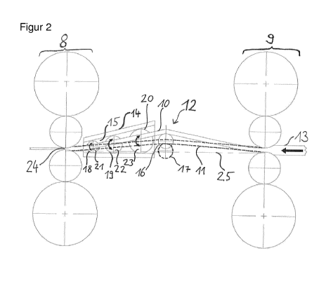
Fig. 2 shows a fragment of a finishing train according to the
invention having an embodiment of a device according to the
invention for lateral guiding, such as is in operation when
installed in a finishing train according to the invention. A
metal strip 13 running by way of different paths 10, 11 across
a loop lifter 12 that is adjustable to various positions
between two roll stands 8, 9 of a finishing train is shown in a
lateral view. The running direction of the metal strip is
illustrated by an arrow. Illustrated is a main member module 14
having a substantially vertical guiding plane 15, said main
member module 14 being disposed between the last roll stand 8
when viewed in the running direction of the strip and the loop
lifter 12. The loop lifter 12 across which the metal strip 13
runs can be set to various positions; this is illustrated for
two positions of the loop lifter roller by way of a solid
outline 16 and a dash outline 17. The path 10 followed by the
metal strip 13 across the topmost potential position of the
loop lifter is illustrated with solid lines; the path 11
followed across the lower position of the loop lifter is
illustrated with dashed lines. The device also comprises three
wear members 18, 19, 20 that are rotatable to a plurality of
rotary positions, wherein the wear faces 21, 22, 23 of the wear
members 18, 19, 20 are substantially planar and in all rotary
positions are parallel to the guiding plane 15 of the main
member module 14. The three wear members 18, 19, 20 are
disposed between the last roll stand 8 when viewed in the
running direction of the strip and the loop lifter 12. When
viewed from the roll gap 24 in the direction of the loop lifter
12, the area of the wear faces 21, 22, 23 of neighboring wear
members 18, 19, 20 increases since the diameter of the three
round wear members 18, 19, 20 increases. In the embodiment
illustrated, each path leads across each wear face 21, 22, 23.
CA 03063996 2019-11-18
PCT/EP2018/064064 - 16 -
2017P00175WO
All wear members 18, 19, 20 contribute to the lateral guiding
independently of the spacings illustrated between the loop
lifter roller and the pass line 25, said pass line being
illustrated by a dashed line. The wear members 18, 19, 20 are
rotated in the operation of the plant illustrated, this being
illustrated by curved arrows, different rotating directions
being possible, while the metal strip 13 is running and is
guided by said wear members 18, 19, 20. An illustration of
parts for lateral guiding that are optionally present between
the loop lifter 12 and the roll stand 9 is dispensed with for
reasons of clarity; this can be, for example, an assembly that
is mirror-symmetrical in relation to the assembly illustrated.
While the invention has been illustrated and described in more
detail by way of the preferred exemplary embodiments, the
invention is not limited by the disclosed exemplars and other
variations can be derived therefrom by the person skilled in
the art without departing from the scope of protection of the
invention.
CA 03063996 2019-11-18
. ,
PCT/EP2018/064064 - 17 -
2017P00175W0
List of reference signs
1 Metal strip
2 Roll stand
3 Roll stand
4 Loop lifter
5a, 5b Wear strips
6 Roll gap
7 Roll gap
8 Roll stand
9 Roll stand
Path
11 Path
12 Loop lifter
13 Metal strip
14 Main member module
Guiding plane
16 Outline of loop lifter roller
17 Outline of loop lifter roller
18 Wear member
19 Wear member
Wear member
21 Wear face
22 Wear face
23 Wear face
24 Roll gap
Pass line
CA 03063996 2019-11-18
PCT/EP2018/064064 - 18 -
2017P00175W0
List of citations
Patent literature
W02015043926A1