Note: Descriptions are shown in the official language in which they were submitted.
VIBRATION REDUCING DRILL STRING SYSTEM AND
METHOD
CROSS-REFERENCE TO RELATED APPLICATIONS
[0001] BACKGROUND
[0002] The invention relates generally to drill strings, such as those used to
access
horizons of interest for oil and gas exploration and production.
[0003] The development of technologies for exploration for and access to
minerals in
subterranean environments has made tremendous strides over past decades. While
wells
may be drilled and worked for many different reasons, of particular interest
are those
used to access petroleum, natural gas, and other fuels Such wells may be
located both on
land and at sea. Particular challenges are posed by both environments, and in
many cases
the sea-based wells are more demanding in terms of design and implementation.
A
particular issue in drilling involves extreme levels of vibration that can be
caused by
interaction of the drill bit at the bottom or far end of a drill string with
geological
structures encountered and that must be traversed to reach horizons of
interest.
[0004] Drill string vibrations are a significant concern during drilling
operations, and are
a common cause of downhole tool failures, failures of more sensitive
equipment, such as
components of a critical bottom hole assembly (BHA), or other part of the
equipment.
Drill string vibrations are typically categorized in three ways. axial (the
drill string is
vibrating along the axis of drilling), lateral (the drill string is vibrating
perpendicular to
the axis of drilling), and torsional (the drill string is rotating along the
axis of rotation).
1
Date Recue/Date Received 2021-05-07
CA 03063998 2019-11-18
WO 2018/213785
PCT/US2018/033513
Vibrations are induced in a multitude of ways including at the drill floor,
the drill bit
cutting rock, rotating an imbalanced mass (sections of the BHA), etc.
[0005] There is a need in the art for improved ways of reducing such
vibration, or for at
least mitigating or localizing some of its effects.
BRIEF DESCRIPTION
[0006] In accordance with certain aspects of the technology, a drill string
comprises a
vibration damping drill pipe section assembled at a location where vibration
damping is
desired, the vibration damping drill pipe section comprising a plurality of
pipe segments
made of a vibration damping material, and a further drill pipe section made of
a different
material less able to dampen vibration experienced by the drill string during
drilling.
[0007] In accordance with a further aspect, the drill string comprises a drill
bit, a bottom
hole assembly adjacent to the drill bit, and a vibration damping drill pipe
section adjacent
to the bottom hole assembly opposite to the drill bit, the vibration damping
drill pipe
section comprising a plurality of pipe segments made of a vibration damping
material. A
further drill pipe section is disposed adjacent to the vibration damping drill
pipe section
opposite the bottom hole assembly and made of a different material less able
to dampen
vibration experienced by the drill string during drilling.
[0008] The techniques also provide a method for making a drill string,
comprising
assembling a drill bit and bottom hole assembly, assembling a vibration
damping drill
pipe section adjacent to the bottom hole assembly as drilling advances into a
well, and
assembling a further drill pipe section adjacent to the vibration damping
drill pipe section
opposite the bottom hole assembly and made of a different material less able
to dampen
vibration experienced by the drill string as drilling advances further into
the well.
2
CA 03063998 2019-11-18
WO 2018/213785
PCT/US2018/033513
DRAWINGS
[0009] These and other features, aspects, and advantages of the present
invention will
become better understood when the following detailed description is read with
reference
to the accompanying drawings in which like characters represent like parts
throughout the
drawings, wherein.
[0010] FIG. 1 is a diagrammatical representation of an exemplary drilling
operation
employing the present techniques;
[0011] FIG. 2 is a diagrammatical representation of a sections of a drill
string
incorporating a vibration damping section,
[0012] FIG. 3 is a diagrammatical representation of another drill string
incorporating
more than one vibration damping sections;
[0013] FIG. 4 is a diagrammatical representation of another drill string
incorporating
more than one vibration damping sections in desired locations;
[0014] FIG. 5 is an idealized exemplary vibration profile comparison between a
drill
string of the prior art and one incorporating a vibration damping section; and
100151 FIG. 6 is a diagrammatical representation of a drill string
incorporating multiple
vibration damping sections along with idealized vibration profiles along the
drill string.
DETAILED DESCRIPTION
[0016] The systems and methods described allow for significantly reduced
vibration of
drill strings and particularly of portions of the drill strings in the region
of sensitive
equipment, such as the BHA. The techniques may be based upon the use of low
modulus
and low density materials in a system that can dampen vibrations, and that can
be applied
to an oil and gas drilling environment with the use of aluminum drill pipe,
titanium drill
3
CA 03063998 2019-11-18
WO 2018/213785
PCT/US2018/033513
pipe, or composite drill pipe that compliments conventional steel pipe. In
some
embodiments materials that may be used may include ductile iron, which may
provide
vibration damping due to its microstructure For example, the low modulus and
density
of aluminum can reduce both the duration and severity of torsional vibrations
in a stick-
slip type dysfunction. The reduction in severity of uncontrolled torsional
oscillations will
reduce the additional strain on threaded connections throughout the BHA and
drill string,
as well as the impact caused by lateral vibrations, and the amplitude of axial
vibrations.
This overall reduction in vibrations can have the benefit of increasing the
life of sensitive
downhole components (and the drill string elements themselves), and increasing
the
efficiency of drilling operations.
[0017] Turning now to the drawings, and referring first to FIG. 1, a well
system is
illustrated and designated generally by the reference numeral 10. The system
is
illustrated as an onshore operation located on the earth's surface 12 although
the present
techniques are not limited to such operations, but may be used in offshore
applications, in
which the drilling and service equipment and systems described would be
located on a
vessel or platform, and the well would be located below a body of water. In
FIG. 1, the
underlying ground or earth is illustrated below the surface such that well
equipment 14 is
positioned near or over one or more wells. One or more subterranean horizons
16 are
traversed by the well, which ultimately leads to one or more horizons of
interest 18. The
well and associated equipment permit, for example, accessing and extracting
the
hydrocarbons located in zones of interest, depending upon the purpose of the
well. In
many applications, the horizons will hold hydrocarbons that will ultimately be
produced
from the well, such as oil and/or gas. The well equipment may be used for any
operation
on the well, such as drilling, completion, workover, and so forth. In many
operations the
installation may be temporarily located at the well site, and additional
components may
be provided. However, in the present context, the tubular strings described
are drill
strings used to access the horizons by cutting or grinding rock and other
subterranean
formations as they are traversed.
4
CA 03063998 2019-11-18
WO 2018/213785
PCT/US2018/033513
[0018] In the illustration of FIG. 1, equipment is very generally shown, but
it will be
understood by those skilled in the art that much this equipment is
conventional and is
found in some form in many such operations. For example, a derrick 14 allows
for
various tools, instruments and tubular strings to be assembled and lowered
into the well,
traversing both the horizons 16 and entering or traversing the particular
horizons of
interest 18. Well or surface equipment 20 will typically include draw works, a
rotary
table, generators, instrumentations, and so forth. Control and monitoring
systems 22
allow for monitoring all aspects of drilling, completion, workover or any
other operations
perfoitned, as well as well conditions, such as pressures, flow rates, depths,
rates of
penetration, and so forth.
[0019] In accordance with the present disclosure, many different tubular
stocks (e.g., drill
pipe) may be provided and used by the operation, and these may be stored on
any suitable
racks or other storage locations. In FIG. 1 a first of these is designated
tubular 1 storage
24, and the second is designated tubular 2 storage 26. As will be appreciated
by those
skilled in the art, such tubular products may comprise lengths of pipe with
connectors at
each end to allow for extended strings to be assembled, typically by screwing
one into the
other, or two tubular products connected via a single coupling. Different
tubular stocks
are used here to allow the operation to balance the technical qualities and
performance
possibilities of each against their costs. That is, one material may be
selected for its
relative strength but lower cost (e.g., steel), while the other is selected
based upon its
superior ability, such as low density and modulus, to be inserted into
extended portions of
the well for vibration damping, although it may be more costly than the first
material. In
presently contemplated embodiments, this second tubular stock may comprise,
aluminum
alloys, for example, but possibly also certain titanium alloys, composite
materials, or
metal matrix alloys. As discussed below, the operation judiciously selects
which material
to use based upon the nature of the well, the well position and geology, and
the desire to
reduce vibration during drilling.
CA 03063998 2019-11-18
WO 2018/213785
PCT/US2018/033513
[0020] In the illustration of FIG. 1, a drill string comprises a first,
generally vertical
section 28 that extends through the upper horizons 16, and an off-vertical
section 30 that
extends through at least a portion of the zone of interest 18. The vertical
section is
formed to access the horizon of interest, and may extend to any desired depth,
such as
7,000 feet to 12,000 feet. The off-vertical section may extend at any desired
angle from
the vertical section, which may be generally perpendicular to the vertical
section,
although other angles for this section may be used. In practice, a well or a
well system
may access a number of locations in one or more horizons of interest by
directional
drilling to create one or more such off-vertical sections. The overall drill
string 32 is
illustrated as already deployed in the well for furthering the well bore
through various
formations and ultimately to the one or more of the formations of particular
interest.
[0021] In this illustrated embodiment, the overall drill string 32 extends
into a generally
vertical section 34 of the wellbore, and into a generally horizontal section
36, as the
wellbore is advanced by action of the drill bit 38. The drill string 32
extends a length 40
through the vertical section 34 of the well and through a length 42 of the off-
vertical
section 36, ultimately to the advancing bit 38. The drill string comprises a
tubular string
(e.g., pipe) that is run into the well during drilling. Such strings may
comprise any
suitable length of tubular products, and the number, size, and materials used
for these will
depend upon a number of factors, but typically the location of the horizon of
interest
(e.g., its depth and the length of the off-vertical section, if any), the
distance to a location
of interest, the depth of the water, if offshore, and so forth. In the
illustrated
embodiment, a bottom hole assembly or BHA 44 is positioned immediately
adjacent to
the bit 38. A length of vibration damping drill pipe 46 is then positioned
adjacent to or
near the BHA to aid in reducing vibrations in the drill string.
[0022] The drill string 32 and will typically be assembled by the well
equipment,
drawing from the tubular materials stored as discussed above. That is, various
tools (e.g.,
drill bit, connectors, BHA with its associated instrumentation) are first
assembled and
placed into the well, followed by lengths of drill pipe by taking the pipe
sections from the
6
CA 03063998 2019-11-18
WO 2018/213785
PCT/US2018/033513
storage, threading them end-to-end, and deploying them progressively into the
well. In
presently contemplated embodiments, some of the drill string is made of
vibration
damping materials, such as aluminum alloy, for example, or another material
that enables
the drill string to attenuate the levels or effects of vibration (e.g.,
titanium alloy,
composite material, metal matrix alloys). The other sections of drill pipe may
be made of
conventional materials, such as steel. As noted above, vibration damping
materials
suitable for use in the present techniques may include ductile iron, at least
partially due to
the damping abilities of its microstructure. The tubular sections assembled in
this way
may comprise, for example, multiple sections of standard length (e.g., 30 or
40 foot
sections) each having industry standard end connectors to facilitate their
assembly. By
way of example only, while the vertical section of the well may extend as much
as 7,000
to 12,000 or more feet vertically into the earth (note that the "vertical"
section need not
be strictly vertical, but may be inclined in at least a part of the well), the
off-horizon
section may extend another 5,000 to 20,000 feet. In some embodiments, as
discussed
below, the vibration damping sections may be placed closest to the BHA,
although other
sections may be placed at other locations in the drill string.
[0023] Axial vibrations are typically manifestations of compressive waves that
travel
along the axis of the drill string. Also called "bit bounce," these vibrations
cause the
cutters on the drill bit to lose depth, reducing effectiveness of the drilling
operations. In
extreme cases, the drill bit loses all contact with the formation, and re-
engages at a high
velocity. This can cause undesirable damage to the bit.
[0024] Torsional vibrations are sometimes referred to as "stick-slip"
vibrations. These
are variations in the rotational speed in the drill string. In extreme cases
(full stick-slip),
the drill bit will stop rotating entirely, allowing for torsional energy to
build up in the drill
string. This torsional energy unwinds in an extremely high angular velocity
release. This
build up and release of the torsional energy causes high stress cycles on the
drill string,
and on the threaded connections in particular. These vibrations are most
severe closer to
7
CA 03063998 2019-11-18
WO 2018/213785
PCT/US2018/033513
the drill bit, which is typically also where the majority of sensitive
components are
located.
[0025] More particularly, torque is applied from the rig floor and transferred
via the drill
string to the drill bit This turning force, along with the weight of the drill
string, allows
the drill bit to cut through subsurface geologic formations. The drill bit is
impregnated
with hardened inserts, or cutters, that are angled such that when an axial
force and
rotational moment are applied, will shear off small sections of rock called
cuttings. The
cuttings are traditionally carried to the surface via a thickened fluid called
"drilling mud"
which is pumped from the surface through drill string, and moves back to
surface through
the annulus formed between the outside of the drill pipe and the newly cut
wellbore. This
process allows the drill string to advance through the formation.
[0026] When drilling normally, the rotation of the drill bit is steady and
predictable. A
dysfunction can occur where the cutters momentarily get stuck, or "stick," on
a section of
rock. Regardless of any sticking or stopping of the bit the drilling rig is
still turning the
drill string at the surface, which causes torsional energy to build up in the
drill string.
After enough time, the increased torsional energy allows for the drill bit to
destroy the
rock that it was stuck on, and be released, or "slip." The built up torsional
energy
dissipates through the bit in the form of increased rotational speed for a
short period of
time, until the excess torsional energy is exhausted. This dysfunction can
occur
repeatedly during drilling operations. When this happens, the drill bit and
tools in the
drill string are forced to accelerate at a rate beyond typical operations.
This change in
rotational speed also affects the amount of rock that is cut during each
rotation of the bit,
slowing down the operations as a whole. These uncontrolled torsional
oscillations of the
drill string reduce the effectiveness of the drilling operations and cost the
operator time
and money. There are various ways to reduce these vibrations, including
momentarily
pausing drilling operations to allow for the vibrations to dampen and
dissipate naturally.
[0027] Lateral vibrations are caused by rotating elements of the drill string,
particularly
elements with a mass imbalance, coupled with friction against the wellbore
wall. This
8
CA 03063998 2019-11-18
WO 2018/213785
PCT/US2018/033513
causes the drill string to oscillate up and down the wellbore wall, and can
cause the drill
string to break contact with the wellbore, and reengage at a high velocity.
Typically
these vibrations are categorized as "forward whirl," where the oscillation of
the drill
string in the borehole is the same rotational direction as the drill string,
and "backward
whirl," where the oscillation is opposite of the rotation of the drill string
A third form,
"chaotic whirl," occurs when the oscillations are not in a pattern which
correlates with
the drill string rotation. These vibrations can cause damage to sensitive
internal
components. ELateral movement is also caused by torsional vibrations. When the
torsional energy is released, drill string elements forcibly shake in the
wellbore and can
impact the wellbore walls at a high velocity. E
[0028] In particular, all drilling activity causes movement of the tubulars
perpendicular to
the axis of the drill string. During rotation of the drill string friction is
generated between
the wellbore wall and the tubulars because of this rotation. This friction
forces the
tubular to ride up one side of the wellbore, and along with other forces
including mass
imbalances in some of the drilling tools, causes the drill string to oscillate
up and down
the well bore wall. In some cases, this movement can become erratic. The
vibrations
resulting from the "whirl" mentioned above are generally referred to as
"lateral
vibrations" and in extreme cases, these vibrations, particularly backward
whirl, cause the
drill string to make contact with the wellbore walls with a high velocity and
acceleration,
called shock, which can cause damage or premature failure to drilling tools
[0029] Mechanical connections affected by the vibration become fatigued far
more
quickly than what would be expected under normal operations. Sensitive
electronic or
mechanical components in a measuring while drilling (MWD) tool are especially
prone to
damage with this type of vibration. These vibrations also cause energy
intended to be
transferred to the bit for the purpose of cutting rock to be expelled
prematurely
throughout the drill string, reducing the rate at which the drill bit cuts
rock.
[0030] Once this vibratory pattern has been realized in the drill string,
measures are often
taken to resolve it as quickly as possible. These measures can include again
momentarily
9
CA 03063998 2019-11-18
WO 2018/213785
PCT/US2018/033513
stopping the drilling operations completely and allowing for the vibrations to
dampen and
subside on their own. This solution is not ideal as it reduces the overall
effectiveness of
the operations. If a sensitive component breaks downhole, the operator is
forced to either
continue drilling "blind" or without the information this tool provides, or do
a "trip" in
which the drill string is pulled to surface so the broken tool can be fixed or
replaced.
These scenarios will likely reduce the quality of the hole being drilled, and
cost the
operator additional time and money.
[0031] More generally, all such vibration reduces the efficiency of the
drilling operation.
That is, ideally, all energy input to the drill string should result in
cutting or removal of
the underground formations and advancement of the drill string. Vibration
ultimately
consumes a portion of this energy, reducing the efficiency of the operation.
Any
reduction in the amount or effects of the vibration should improve this
drilling efficiency.
[0032] The techniques described allow for reduction, damping, attenuation, or
reduction
of the effect of some or all of these foims of vibration. In particular,
introducing into the
drill string a specified length of drill pipe made of a vibration damping
material (e.g.,
aluminum) can reduce the magnitude and duration of both torsional and lateral
vibrations.
Due to the low modulus and low density of such alloys, the material is able to
absorb
vibrations that would otherwise be transmitted to other components in the
drill string. A
relatively small amount of aluminum drill pipe may suffice relative to the
length of the
entire drill string. Currently this length is theorized to be between 500 and
2,000 feet in a
drill string that can be between 10,000 and 30,000 feet overall. In some
embodiments,
the length of a vibration damping section may be reduced to one stand
(typically three 40
foot joints, or 120 feet). Introducing the aluminum drill pipe would reduce
delays in
drilling operations and avoid damage done to sensitive components,
significantly
increasing the effectiveness of the drilling operations.
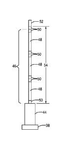
[0033] FIG. 2 illustrates a section of a drill string assembled to reduce
vibration. In this
illustration, the drill bit 38 is shown adjacent to the BHA 44. The vibration
damping drill
string section or stand 46 is shown as comprising 3 segments of pipe 48, with
screwed
CA 03063998 2019-11-18
WO 2018/213785
PCT/US2018/033513
connections 50 between them and at ends of the section. At the upper end of
the
vibration damping section 46 begins a section of conventional drill pipe 52.
The
vibration damping section extends over a desired length 54 selected to provide
the
desired vibration damping. Presently contemplated lengths 54 may between 90
and 2,000
feet in length, and may be made up of pipe segments of 30 or 40 feet (standard
lengths).
By comparison, the BHA may be some 100-300 feet in length, while the overall
drill
string will typically be many thousands of feet long.
[0034] In some embodiments and environments it may be useful to provide more
than
one vibration damping section. FIG. 3 illustrates such a drill string. In this
case, a first
vibration damping section 46 is again provided near the BHA 44, with a section
of
conventional steel pipe 52 connected above it. Then above that section,
another length of
vibration damping pipe 46' if provided, followed by another section of
conventional drill
pipe 52'. Further sections of vibration damping pipe may also be provided
further along
the drill string. It should be noted, as well, that vibration damping sections
may be
placed anywhere along the string, with multiple such sections being separated
by
conventional tubular products. In some embodiments, for example, it may be
useful to
place vibration damping sections every two or more thousand feet. Such
placement may
depend upon such factors as the size of the tubular product, the loads
encountered, the
well conditions, and so forth.
[0035] In certain well and borehole profiles and trajectories, such vibration
damping
sections may be judiciously located to provide desired damping in regions
where such
vibration is anticipated to be particularly troublesome. FIG. 4 illustrates an
application in
which a wellbore has vertical and off-vertical sections 34 and 36 as discussed
above, with
a heel section 56 transitioning between the two. A vibration damping drill
pipe section
46 is here again positioned adjacent to the BHA 44. But to help reduce
anticipated
vibration above the heel section 56 of the wellbore, the drill string has a
further vibration
damping section 46' that may be added to the drill string in a location that
will be
deployed at, around, or above the heel section.
11
CA 03063998 2019-11-18
WO 2018/213785
PCT/US2018/033513
[0036] It is believed that the presence of the vibration damping drill pipe
sections, even
in relatively short sections as compared to the overall drill string may
significantly affect
the vibration experienced by the drill string, and particularly by those
components near
the vibration damping sections, such as the BHA and/or the drill bit. FIG. 5
is a graphical
representation 58 of anticipated effects on vibration at such locations. In
this illustration,
vibration magnitude 60 is shown by a vertical axis over time along a
horizontal axis 62.
The dashed trace 64 represents a vibration profile of a conventional drill
string at a
location of the BHA or drill bit. Significant peaks 66 can be anticipated at a
frequency
corresponding to the dynamics of movement of the end of the drill pipe during
drilling.
A vibration profile of a drill string having at least one vibration damping
section adjacent
to this location is represented by the solid trace having significantly
reduced peaks, and
ultimately settling into a higher frequency, lower peak, and lower variability
dynamic
region 70.
[0037] Similar attenuations are anticipated for drill strings having more than
one
vibration damping sections, as illustrated in FIG. 6. Here, a drill string
similar to that of
FIG. 3 is shown along with vibration profile comparison graphs 72 and 74 at
locations
adjacent to the vibration damping sections.
[0038] The material properties believed to be of particular interest in
reducing vibration
include modulus of elasticity, density, and damping characteristics. Regarding
the
modulus of elasticity, conventional steels used for well tubulars have a
modulus typically
on the order of 29.5 Mpsi, with typical ranges of 27 to 31 Mpsi. Aluminum
alloy
tubulars suitable for the present techniques have a modulus typically on the
order of 10
Mpsi, with typical ranges of 9 to 11.5 Mpsi. Titanium tubulars contemplated
for the
present techniques, on the other hand, have a modulus typically on the order
of 16.5
million psi, with typical ranges of 13.5 to 17 Mpsi. Suitable composites can
be made to
have a very low modulus, such as on the order of 5 Mpsi if required. Regarding
the
relative density of such materials, typical steel has a density of 0.285
pounds per cubic
inch, aluminum has a typical density of 0.101 lbs./inA3, titanium has a
typical density of
12
CA 03063998 2019-11-18
WO 2018/213785
PCT/US2018/033513
0.165 lbslin^3, and composites can have densities ranging from less than 0.101
lbs./inA3
to more than 0.285 lbslin^.3.
[0039] Other properties may also be of interest, including properties related
to the ability
or tendency for such materials to convert vibrational movement to heat,
thereby wasting
or dissipating energy that could otherwise be used to advance the well. For
example the
internal friction and damping capacity of the material may be considered in
the selection.
[0040] Regarding the specific materials that may be used, presently
contemplated
tubulars may be selected from aluminum tubulars, for example, from 2000, 6000,
and
7000 series alloys, while titanium tubulars may be selected from so-called
Alpha, Alpha-
Beta and Beta alloy families. Suitable composites may include carbon fiber
compositions
or metal matrix alloys. As noted above, ductile iron products may also be
usefully
employed.
[0041] In practice, various methods may be employed for carrying out the drill
string
vibration damping approach discussed above. In general, the tool or tools that
precede
the vibration damping section will be assembled at the wellsite, and the
drilling
commenced. The vibration damping section will then be assembled along a
desired
length, such as adjacent to the BHA. As the drilling advances, the desired
length of the
vibration damping drill pipe is ultimately reached by attachment of successive
lengths of
the tubulars, followed by attachment of conventional drill pipe (e.g. steel).
Then at
further desired locations one or more additional lengths of vibration damping
pipe may
be inserted. In most cases the length of the vibration damping drill pipe may
be
estimated or calculated in advance based upon the anticipated well conditions.
In some
cases the additional sections may be inserted based upon vibrations actually
experienced
during drilling. In still other situations, the drill string may be fully or
partially removed
("tripped out") and one or more vibration damping sections maybe added due to
vibration
experienced or anticipated.
13
[0042] While only certain features of the invention have been illustrated and
described
herein, many modifications and changes will occur to those skilled in the art.
It is,
therefore, to be understood that the appended claims are intended to cover all
such
modifications and changes as fall within the tme spirit of the invention
14
Date Recue/Date Received 2021-05-07