Note: Descriptions are shown in the official language in which they were submitted.
CA 03064147 2019-07-26
FURNITURE HINGE HAVING A BLOCKING ELEMENT FOR A LINEAR
DAMPER
The invention relates to a furniture hinge for articulated fixing of a
furniture door,
flap or the like to a furniture carcass, having a hinge member having a hinge
cup
and a hinge arm which is pivotably connected to the hinge cup and which can be
secured to one of the furniture components, and having an assembly member
which can be secured to the other furniture component, having a linear damper
for
damping at least the closure movement of the furniture hinge, having a locking
element which can be adjusted into at least two switching positions and by
means
of which the linear damper is blocked in a locking switching position in the
retracted position thereof and is released in a damping switching position,
wherein
in the locking switching position a locking bolt which is pivotably supported
about a
rotation axis of the locking element is pivoted into the adjustment region of
the
linear damper or a component which is connected to the linear damper and in
the
damping switching position is pivoted out of the adjustment region.
WO 2013/149632 Al discloses a damping element for installation in a hinge cup
of
.. a furniture hinge. A resiliently tensioned damper cylinder may be
introduced into
the adjustment path of a portion of the furniture hinge and a closure movement
of
the furniture hinge may thereby be damped. The adjustment region and
consequently the damping action of the damping element may be adjusted by
means of an adjustment element which is intended to be operated without tools,
.. for example, in predetermined stages. To this end, a blocking portion of
the
adjustment element is adjusted in terms of its position in such a manner that
a
stop, which is connected to the damping cylinder and which is moved therewith
when the damping cylinder is deployed into a first position of the adjustment
element, strikes the blocking portion and is thereby secured and in a second
position is not. Depending on the position of the blocking portion, the
adjustment
region and consequently the damping action of the damping element is
1
CA 03064147 2019-07-26
accordingly limited. The blocking portion and the stop are constructed in such
a
manner that the damping cylinder can also be inserted in the first position of
the
adjustment element. When the furniture hinge is opened, the stop then strikes
the
blocking portion of the adjustment element and the damping cylinder is not or
only
partially deployed. WO 2013/149632 Al sets out two construction variants for
the
adjustment element. In a first construction variant, the adjustment element is
constructed as a rotary arrangement having an operating portion and blocking
portion which can be adjusted about a rotation axis. In this instance, the
rotation
axis is orientated perpendicularly to the movement direction of the damper
cylinder
and consequently of the stop. The blocking portion is consequently screwed in
on
a circular path in the movement direction of the damper cylinder in the
adjustment
path of the stop. The resilient force for deployment of the damper cylinder is
consequently transmitted from the stop in an actuation direction of the
adjustment
element to the blocking portion. There must be provided corresponding locking
devices which prevent unintentional adjustment of the adjustment element as a
result of the active resilient force from the first position thereof in the
direction of
the second position thereof. In particular with a cost-effective production of
the
damping element or the locking devices of plastics material and repeated
actuation of the adjustment element, the locking devices may become worn so
that
.. a secure fixing of the damping cylinder counter to the acting resilient
force is no
longer possible. A reduction of the damping action of the furniture hinge is
then no
longer possible. In a second construction variant for the adjustment element,
WO
2013/149632 Al proposes a linearly adjustable sliding element, wherein a
portion
of the sliding element can be inserted into the adjustment path of the stop of
the
damping cylinder transversely relative to the movement direction thereof. The
movement directions of the adjustment element and the damping cylinder are
accordingly orientated transversely relative to each other, whereby an
unintentional adjustment of the sliding element is reliably prevented by the
resilient
force acting on the stop. However, such a sliding element has a tendency to
become caught during adjustment. There is thereby less operating comfort
compared with a rotary actuation.
2
CA 03064147 2019-07-26
WO 2009/124332 Al sets out a damping device for a furniture fitting. A curved
actuation element is arranged in a hinge cup so as to be supported in a
pivotable
manner about a rotation axis. The rotation axis is in this instance orientated
in
accordance with the pivot axis of the furniture hinge. A rotor and a rotation
damper
are connected to the actuation element laterally and opposite. Both act in a
pivot
direction of the actuation element. The actuation element is introduced into
the
adjustment path of an articulated lever of the furniture hinge and is pivoted
thereby
about the rotation axis thereof when the furniture hinge is folded in. The
pivot
movement is in this instance damped by the rotation damper. As a result of the
rotor, a resilient force opposed to the closure movement is transmitted to the
actuation element. When the furniture hinge is folded open, the actuation
element
is thereby adjusted again into the original position thereof into the
adjustment path
of the articulated lever. The rotor has at the periphery thereof recesses in
which a
securing element can be inserted by means of a linear sliding member. The
adjustment path of the actuation element can thereby be limited. The
embodiment
of the damping device with a rotation damper and a rotor is complex and
accordingly cost-intensive.
EP 2 766 547 B1 discloses a furniture hinge with a linear damper and a return
spring. The damper and the return spring counteract a closure of the furniture
hinge. They are constructed separately and act on a common sliding member
which is introduced into the adjustment path of a hinge arm. The expansion of
the
spring can be blocked by means of a blocking element. This element is, for
example, constructed as a sliding element. The blocking element may also be
constructed as a hook which can be pivoted about an axis which is orientated
transversely relative to the movement direction of the return spring and when
actuated engages in the windings of the spring.
An object of the invention is to provide a damped furniture hinge which
enables
reliable switching on and switching off of the damping effect.
3
CA 03064147 2019-07-26
The object of the invention is achieved by the rotation axis of the locking
element
being orientated in the movement direction of the linear damper. The locking
bolt
of the locking element is consequently pivoted transversely relative to the
movement direction or active direction of the linear damper into the
adjustment
region of the linear damper or the component which is connected to the linear
damper. Opening forces of the linear damper orientated in the direction of the
deployed position of the linear damper thereby act transversely relative to
the
adjustment direction of the locking bolt. No forces acting in the adjustment
direction of the locking element are consequently transmitted from the linear
damper to the locking bolt. The switching position of the locking element
therefore
cannot be unintentionally adjusted by the linear damper.
A simple and rapid adjustment of the switching position of the locking element
can
thereby be enabled by the locking element being intended to be adjusted
without
tools.
According to a preferred construction variant of the invention, there may be
provision for the locking element to have a rotary member which is supported
so
as to be able to be rotated about the rotation axis of the locking element and
on
which the locking bolt and, in a state offset angularly relative thereto, a
handle are
secured, preferably formed on. The locking element may thus be orientated to
face
the linear damper, whilst the handle is orientated for easily accessible
operation of
the locking element. As a result of the coupling of the locking bolt and the
handle
to the rotary member, an actuation of the handle is transmitted directly to
the
locking bolt.
Preferably, there may be provision for the rotary member to be supported on a
bearing pin in such a manner that the bearing pin is supported in a locking
element
housing and the locking bolt and the handle are guided through openings out of
the locking element housing. A mechanically protected and nonetheless simple
4
CA 03064147 2019-07-26
construction of the locking element is thereby produced. This element can be
assembled in a simple manner as a structural unit on a furniture hinge. In a
particularly preferred manner, the rotary member, the locking bolt and the
handle
are constructed integrally, for example, as a plastics material component
which
can be produced in a cost-effective manner.
In order to prevent unintentional adjustment of the locking element by a user
and
to enable a precise adjustment of the switching positions, there may be
provision
for the rotation of the locking bolt to be locked in the switching positions
of the
locking element by means of at least one locking device.
A precise orientation and securing of the locking element to a furniture hinge
is
enabled by the locking element housing having at least one locking attachment
by
means of which the locking element housing can be secured to the hinge cup of
.. the furniture hinge. It is consequently ensured that the locking bolt is
orientated in
accordance with the respective switching position thereof in a precise manner
relative to the linear damper.
According to a preferred construction variant of the invention, there may be
provision for the locking bolt to have an inclined start-up member and
opposite a
blocking face, in the locking switching position and with the linear damper
deployed for the inclined start-up member to be orientated so as to be facing
the
linear damper or the component which is connected to the linear damper and, in
the locking switching position and with the linear damper retracted, for the
blocking
face to be orientated so as to face the linear damper or the component which
is
connected to the linear damper. Preferably, there may further be provision for
a
blocking attachment to be secured to a movably supported cylinder or a movably
supported piston of the linear damper, for the blocking attachment to have an
attachment inclination and opposite a blocking counter-face, in the locking
switching position and with the linear damper deployed, for the attachment
inclination to be orientated to face the locking bolt and, in the locking
switching
5
CA 03064147 2019-07-26
position and with the linear damper retracted, for the blocking counter-face
to be
orientated so as to face the locking bolt. The locking element can be actuated
with
the furniture door, flap or the like open. Starting from the damping switching
position of the locking element, the linear damper is then deployed. By
switching
the locking element into its locking switching position, the locking bolt is
pivoted
into the movement path of the blocking attachment. During subsequent closure
of
the furniture door, flap or the like and consequently of the furniture hinge,
the
linear damper is pushed together. In this instance, the blocking attachment
with
the attachment inclination thereof strikes the inclined start-up member of the
locking bolt. The attachment inclination and the inclined start-up member form
sliding faces along which the blocking attachment slides past the locking
bolt.
When the retracted end position of the linear damper is reached, the blocking
attachment and the locking bolt are arranged laterally with respect to each
other in
such a manner that the blocking face of the locking bolt abuts the blocking
counter-face of the blocking attachment. Sliding out the linear damper during
the
next opening of the furniture door, flap or the like and consequently of the
furniture
hinge is thereby blocked. The blocking face and the blocking counter-face are
preferably orientated transversely relative to the movement direction of the
linear
damper and consequently the blocking attachment. The linear damper is thereby
prevented in the locking switching position from being able to slide past the
locking
bolt from the retracted position thereof or the locking element is prevented
from
being displaced into the damping switching position thereof as a result of the
restoring forces transmitted from the linear damper to the locking bolt. The
formation of the locking bolt and the blocking attachment make it possible for
the
locking element to be able to be operated with the furniture door, flap or the
like
open, the linear damper also to be able to be retracted in the locking
switching
position of the locking element and the linear damper to be retained securely
in the
retracted position thereof when the furniture door, flap or the like is next
opened.
If there is provision for the locking bolt to be constructed resiliently at
least in the
pivot direction of the locking element, the locking bolt in the locking
switching
6
CA 03064147 2019-07-26
position can thus be pressed to the side when the linear damper is retracted
by the
attachment inclination and inclined start-up member sliding past each other.
The
path is thereby released so that the blocking attachment can be guided past
the
locking bolt and consequently the linear damper can be adjusted into the
retracted
end position thereof. When the end position of the linear damper is reached,
the
locking bolt returns as a result of the resilience thereof into its original
position
again so that the blocking face thereof abuts the blocking counter-face of the
blocking attachment.
According to a preferred embodiment of the invention, there may be provision
for
the linear damper to be at least partially arranged and guided in a housing,
for the
hinge cup of the furniture hinge to have an assembly region which is reduced
in
terms of the cup depth thereof and which is terminated at the base side by a
cover, for the housing in the assembly region to be secured from the outer
side to
the cover of the hinge cup, for a movably supported portion of the linear
damper to
be guided through an opening into the inner region of the hinge cup and the
pivot
region of the hinge arm of the furniture hinge and for the locking element to
be
secured in a recess of the cover in such a manner that the handle of the
locking
element is arranged in the inner region and the locking bolt is arranged in
the outer
region of the hinge cup. The linear damper is thus arranged outside the hinge
cup
and consequently protected. The inner space of the hinge cup is free and can
thereby be easily cleaned. The locking element can be operated from the inner
space of the hinge cup and engages outside the hinge cup in the adjustment
path
of the linear damper or the blocking attachment which is connected to the
linear
damper.
There is provision for the housing facing the locking element to have a wall
recess
through which the locking bolt is guided into the housing, the movable
components
of the linear damper and preferably also of the locking element are thus
protected
in each case and arranged so as to be able to be easily mounted in housings.
The
7
CA 03064147 2019-07-26
locking bolt can be introduced through the wall recess into the adjustment
path of
the damper.
A simple assembly of the furniture door, flap or the like on the furniture
carcass
can be achieved by the hinge arm being able to be indirectly or directly
secured to
the assembly member by means of a connection system which is intended to be
closed without tools. The hinge arm with the hinge cup can thereby be secured,
for
example, to the furniture door, flap or the like and the assembly member to
the
furniture carcass. The actual assembly of the furniture door, flap or the like
to the
furniture carcass is then carried out without tools. A fitter consequently
does not
have to guide any tool and has both hands free for the assembly of the
furniture
door, flap or the like. Since he preferably also requires no tool for the
adjustment
of the switching position of the locking element, the assembly of the
furniture door
and adjustment of the damping can be carried out in a simple and rapid manner.
The invention is explained in greater detail below with reference to an
embodiment
illustrated in the drawings:
In the drawings:
Fig. 1 is
a perspective view of an item of furniture with an articulated
furniture door;
Fig. 2 is an exploded illustration of an assembly member for securing
the furniture hinge to a furniture carcass;
Fig. 3 is
a plan view of the assembled assembly member shown in
Figure 2,
8
CA 03064147 2019-07-26
Fig. 4 is a perspective view of the assembly member shown in
Figure 3,
Fig. 5 is a lateral sectioned illustration of the assembly
member
shown in Figure 3,
Fig. 6 is an exploded view of a hinge member having a hinge cup
for
securing the furniture hinge to a furniture door, flap or the like;
Fig. 7 is a plan view of the assembled hinge member shown in
Figure 6,
Fig. 8 is a perspective view of the hinge member shown in Figure
7,
Fig. 9 is a lateral sectioned illustration of the hinge member shown in
Figure 7,
Fig. 10 is a perspective view of the hinge member and the
assembly
member in a position orientated with respect to each other,
Fig. 11 is a perspective view of the assembled furniture hinge,
Fig. 12 is a plan view of the furniture hinge shown in Figure 11,
Fig. 13 is a lateral sectioned illustration of the furniture hinge shown in
Figure 11,
Fig. 14 is a side view of the furniture hinge mounted on an item
of
furniture,
Fig. 15 is a perspective exploded view of a locking element,
9
CA 03064147 2019-07-26
Fig. 16 is a perspective view of a linear damper having a
housing,
Fig. 17 is a plan view of a hinge cup of the furniture hinge,
and
Fig. 18 is a lateral sectioned illustration of the hinge cup
shown in
Figure 17.
Figure 1 is a perspective view of an item of furniture 2 having an articulated
furniture door 5. It is conceivable in place of the furniture door 5 to also
provide a
flap or other furniture component which is connected to the item of furniture
2 so
as to be able to be folded. The furniture door 5 is secured with two furniture
hinges
1 to a frame 4 of a furniture carcass 3. An assembly member 6 and a hinge
member 7 are associated with each furniture hinge 1. The hinge member 7 is
connected to the furniture door 5. The assembly member 6 is secured to the
frame
4. In this instance, the assembly member 6 is secured to the end side of the
frame
4. Such a form of assembly is also known as Face Frame and is in particular
used
in the US American market. The furniture hinges 1 enable the furniture door 5
to
be opened and closed in a pivoting movement.
A coordinate system 8 shows, with respect to the orientation of the item of
furniture 3, three spatial directions, that is to say, an x direction 8.1, a y
direction
8.2 and a z direction 8.3. The spatial directions indicate possible adjustment
directions of the furniture door 5, as enabled by the furniture hinges 1.
Figure 2 is an exploded view of the assembly body 6 for securing the furniture
hinge 1 to the furniture carcass 3. A base carrier 10 and a blocking element
20 are
associated with the assembly member 6.
10
CA 03064147 2019-07-26
The base carrier 10 serves to secure the assembly body 6 to the item of
furniture 2
shown in Figure 1. It is preferably constructed for this purpose as a punched
component, in particular as a punched metal sheet component. An assembly
portion 11 of the assembly member 6 is constructed in a plate-like manner. It
has
.. a recess 12. Facing away from the viewer, the base carrier 10 forms in the
region
of the assembly portion 11 an assembly face 10.1. The assembly face 10.1 is
delimited by two inner stops 13 and two outer stops 14, which face each other
in
an assembly direction 9.1 illustrated by an arrow. The stops 13, 14 are
constructed
as angled flaps which are formed on the assembly portion 11. They are
orientated
in such a manner that they protrude beyond the assembly face 10.1.
Laterally and opposite each other, two lateral guides 15 are formed on the
assembly portion 11 of the base carrier 10 in each case. The lateral guides 15
are
in this instance arranged along the edges of the assembly portion 11 arranged
transversely relative to the assembly direction 9.1. They are angled with
respect to
the assembly portion 11 and orientated so as to face away from the assembly
face
10.1. At the end side, the lateral guides 15 are angled in such a manner that
the
terminal edges of the lateral guides 15 which are arranged opposite each other
face each other. The lateral guides 15 consequently form in each case a
lateral
portion 15.1 and a covering portion 15.2 which is formed thereon, which
portions,
together with the assembly portion 11, in each case surround a guiding groove
15.4. The lateral guides 15 opposite, guiding grooves 15.4 face each other.
They
form a sliding guide 15.3. The sliding guide 15.3 is orientated in the
assembly
direction 9.1.
Via a graduation 16.1, a retention attachment 16 is secured to the assembly
portion 11. The retention attachment 16 is formed outside the region delimited
by
the stops 13, 14 on the assembly portion 11. Two retention webs 17 are formed
laterally on the retention attachment 16. The retention webs 17 are
constructed as
.. flaps which are angled with respect to the retention attachment 16.
Preferably, the
retention webs 17 are arranged at an angle of 900 with respect to the
retention
11
CA 03064147 2019-07-26
attachment 16. They are in this instance angled in the direction facing away
from
the assembly face 10.1. The surface normals of the retention webs 17 are
orientated transversely relative to the assembly direction 9.1. Each of the
retention
webs 17 is penetrated by an axial hole 17.1. The axial holes 17.1 of the
retention
webs 17 which are arranged opposite each other are orientated in alignment
with
each other. In the region between the retention webs 17, burled spring guides
18
are formed on the edge of the retention attachment 16.
The blocking element 20 is constructed in a curved manner. It has a planar
actuation portion 21 on which laterally angled articulated portions 22 are
formed.
In the articulated portions 22, an axle receiving member 22.1 in the form of a
hole
is introduced in each case. The axle receiving members 22.1 are orientated in
alignment with each other. The articulated portions 22 are orientated in such
a
manner that with the assembly member 6 mounted, they are arranged laterally
and with slight spacing relative to the retention webs 17 of the base carrier
10. The
axle receiving members 22.1 are then orientated in alignment with the axial
holes
17.1 of the retention webs 17. In a state concealed or partially concealed by
the
actuation portion 21, retention portions 23, as shown in Figure 5, are formed
on
the actuation portion 21. The retention portions 23 are in this instance
arranged on
the edge of the actuation portion 21 orientated counter to the assembly
direction
9.1. They are constructed in the form of flaps and angled with respect to the
actuation portion 21 in the direction of the retention attachment 16. It is
also
conceivable to provide a continuous retention portion 23 along the edge of the
actuation portion 21. The actuation portion 21 forms at the side thereof
facing
away from the retention attachment 16 an actuation side 21.1 and opposite it a
resilient abutment face 21.2. In order to improve the sensation, the actuation
side
21.1 has a structured surface.
An axle 26 is further associated with the assembly member 6. The axle 26 has
at
the end sides stops in the form of expansions 26.1. In this instance, at least
one of
the expansions 26.1 is fitted only during the assembly of the assembly member
6.
12
CA 03064147 2019-07-26
Two springs 25 are associated with the blocking element 20. The springs 25
each
have an angled region 25.1 which is connected to a resilient curved member
25.3.
The ends of the springs 25 are constructed as legs 25.2. The legs 25.2 of the
springs 25 are orientated in the direction of the spring abutment face 21.1 of
the
blocking element 20 and the curved resilient member 25.3 in the direction of
the
surface of the retention attachment 16.
Figure 3 is a plan view of the assembled assembly member 6 shown in Figure 2.
The same components are designated as introduced in relation to Figure 2. The
blocking element 20 is pivotably connected by means of the axle 26 to the base
carrier 10 of the assembly member 6. To this end, as can clearly be seen in
Figure
4, the articulated portions 22 are arranged laterally outside the retention
webs 17
and the axle 26 is inserted through the now aligned axle receiving members
22.1
and axial holes 17.1, as shown in Figure 2. At the end side, the expansions
26.1
are formed on the axle 26 so that they cannot unintentionally be pushed out of
the
axial holes 17.1 and axle receiving members 22.1. The axle 26 thus forms a
rotation axis for the blocking element 20. This axis is arranged in the
assembly
direction 9.1 in extension of the sliding guide 15.3 The springs 25 are
inserted in a
pretensioned state between the spring abutment face 21.2 of the actuation
portion
21 as shown in Figure 2 and the opposing side of the retention attachment 16
of
the base carrier 10. They consequently press the blocking element 20 into the
closure position thereof. In this closure position, the blocking element 20
abuts the
retention attachment 16 with the retention portions 23 shown in Figure 2.
With reference to the description relating to Figure 3, Figure 4 is a
perspective
view of the assembly member 6 shown in Figure 3. In this perspective view, the
arrangement of the springs 25 can be clearly seen. The curved resilient
members
25.3 abut at the side of the retention attachment 16 facing the blocking
element
20. They are guided laterally through the spring guides 18 formed on the
retention
attachment 16. The legs 25.2 of the springs 25 abut the spring abutment face
21.2
13
CA 03064147 2019-07-26
of the actuation portion 21 of the blocking element 20. As a result of the
pretensioning of the springs 25, the blocking element 20 is adjusted into the
closure position thereof.
Figure 5 is a lateral sectioned illustration of the assembly member 6 shown in
Figure 3. In this instance, the path of the section follows the line of
section
indicated V in Figure 3. The base carrier 10 has in the assembly portion 11
thereof
the assembly face 10.1, with which the assembly member 6 abuts the furniture
carcass 3 when the furniture hinge 1 is assembled. The inner and outer stops
13,
14 are formed on the assembly portion 11 and protrude over the assembly face
10.1. The assembly face 10.1 is consequently delimited by the stops 13,14. The
assembly member 6 can thus be placed with the assembly face 10.1 on the frame
4 of a furniture carcass 3 and can using at least two of the stops 13, 14 be
orientated relative thereto. The lateral guides 15 are formed laterally on the
base
carrier 10. The guiding grooves 15.4 are in this instance orientated in the
direction
toward the assembly portion 11. Together with the opposing lateral guides 15
and
the assembly portion 11, the guiding grooves 15.4 form a sliding guide 15.3
This is
orientated in the assembly direction 9.1 The assembly portion 11 merges via
the
graduation 16.1 into the retention portion 16. This portion is orientated so
as to be
offset parallel with the assembly portion 11. The blocking element 20 is
pivotably
connected by means of the axle 26 to the retention webs 17 of the base carrier
10.
To this end, the axle 26, as described with reference to Figure 3, is inserted
through the axial holes 17.1 of the retention webs 17 which are arranged
opposite
each other and the axle receiving members 22.1 which are formed in the
articulated portions 22 of the blocking element 20. The springs 25 are each
fitted
with the winding region 25.1 thereof on the axle 26. In this instance, the
legs 25.2
of the springs 25 abut the spring abutment face 21.2 of the blocking element
20.
The curved resilient members 25.3 abut the retention attachment 16. They are
guided laterally through the spring guides 18 formed on the retention
attachment
16. The springs 25 are pretensioned. A torque which is directed counter to an
actuation direction 9.2 indicated by an arrow is thereby transmitted to the
blocking
14
CA 03064147 2019-07-26
element 20. The blocking element 20 is thereby adjusted about the rotation
axis
thereof formed by the axle 26 into the closure position shown and retained. In
this
closure position, the retention portions 23 abut the retention attachment 16.
As a
result of the graduation 16.1, it is possible for the rotation axis formed by
the axle
26 to be arranged in extension of the sliding guide 15.3. As a result of a
pressure
at the actuation side 21.1, the blocking element 20 can be adjusted counter to
the
resilient force in accordance with the actuation direction 9.2 from the
closure
position shown into an open position.
.. Figure 6 is an exploded view of a hinge member 7 with a hinge cup 30 for
securing
the furniture hinge 1 to a furniture door 5, flap or the like. A hinge arm 40
and in
this instance an intermediate portion 80 and a connection element 50 are
further
associated with the hinge member 7.
As shown in Figure 1, the hinge cup 30 can be introduced into a hole in the
furniture door 5 and using screws which are guided through lateral flanges 33
formed laterally on the hinge cup 30 can be screwed to the furniture door 5,
flap or
the like. To this end, the lateral flanges 33 are penetrated by assembly holes
33.1.
A centering region 31 forms, starting from an outer abutment face 32, a recess
which merges into an assembly region 34 (see Figure 9) of the hinge cup 30
which
is also constructed as a recess. In the direction toward the furniture door 5,
the
hinge cup 30 is terminated in the assembly region 34 by a cover 37. Locking
recesses in the form of apertures are introduced in the cover 37. Locking
elements
73 are engaged in the locking recesses. The locking elements 73 are part of a
housing 70 shown in Figure 11 for receiving a linear damper 60. The linear
damper 60 is consequently arranged outside the hinge cup 30 below the cover 37
of the assembly region 34. In order to provide sufficient space for receiving
the
linear damper 60, the cover 37 has a formation 37.1 along which the linear
damper
60 is arranged.
15
CA 03064147 2019-07-26
A portion of the linear damper 60 is introduced through an opening 35 in the
centering region 31. In the embodiment shown, a movably supported cylinder 61
of the linear damper 100 is introduced into the centering region 31. The
cylinder 61
has at the end side an inclination 62. A locking element 100 is inserted in a
recess
of the cover 37. Using the locking element 100, the linear damper 60 can be
blocked in a retracted position so that the inclination 62 is not guided into
the
centering region 31.
A second spring 38 is also arranged outside the hinge cup 30. It is guided
with the
free ends 38.2 thereof through the opening 35 into the centering region 31.
The
second spring 38 which is constructed as a leg spring has a winding 38.3 and a
second curved resilient member 38.1.
The centering region 31 is formed by cup side walls 31.2, a rounded portion
31.4
and a cup base 31.1. In the opposing cup side walls 31.2, articulated
receiving
members 31.3 in the form of holes are introduced. An articulated pin 39 with
end-
side stop portions 39.1 is associated with the articulated receiving members
31.3.
In this instance, a stop portion 39.1 is formed on the articulated pin 39 only
when
the hinge member 7 is assembled.
The hinge arm 40 has an articulated lever 43. At the end side and facing the
hinge
cup 30, a pin receiving member 41 is formed on the articulated lever 43, as
shown
in greater detail in Figure 9. The pin receiving member 41 is constructed as a
cylindrically bent end region of the articulated lever 43. In the region of
the pin
receiving member 41, two guiding curves 42 are arranged on the articulated
lever
43 in a laterally opposed manner.
The articulated lever 43 is integrally connected to a securing portion 44 of
the
hinge arm 40. It is also conceivable for the articulated lever 43 and the
securing
portion 44 to be constructed separately and to be connected to each other, for
example, using securing means. Preferably, the securing portion 44 is
constructed
16
CA 03064147 2019-07-26
as a punched component. It has side regions 44.2 which are angled laterally in
the
direction toward the connection element 50. These regions form guiding faces
41.1 which are orientated in the direction of the longitudinal extent of the
hinge
arm 40. A threaded receiving member 45 and a recess 46 are introduced into the
securing portion 44. Via a graduation, an attachment piece 44.3 is formed on
the
securing portion 44. The plane of the attachment piece 44.3 is in this
instance
arranged so as to be offset in the direction toward the intermediate portion
80 with
respect to the plane of the securing portion 44. The attachment piece 44.3 is
penetrated by an X-cam guide 47 in the form of an elongate hole.
The intermediate portion 80 is arranged between the hinge arm 40 and the
connection element 50 and orientated for assembly with the hinge arm 40 and
the
connection element 50. The intermediate portion 80 has an abutment portion 81
which is constructed in a planar manner and on which an attachment 82 which is
also constructed in a planar manner is formed. The plane of the attachment 82
is
in this instance offset with respect to the plane of the abutment portion 8.1
in the
direction toward the hinge arm 40. The attachment 82 is arranged opposite the
attachment piece 44.3 of the hinge arm 40. The attachment 82 is in this
instance
connected to the abutment portion 81 by means of three webs 81.2 which are
orientated in the direction toward the hinge arm 40. Between the webs 81.2,
the
abutment portion 81 has in each case an extension in the form of guiding flaps
81.1. In the attachment 82, an X-cam bearing 83 in the form of a hole is
introduced
in alignment with the X-cam guide 47. Opposite the recess 46 of the hinge arm
40,
a Y-cam guide 84 in the form of an elongate hole and a through-opening 86 are
formed in the abutment portion 81. Opposite the Y-cam guide 84, a Y-guiding
cam
89 is fitted to the abutment portion 81. The Y-guiding cam 89 is guided
through the
abutment portion 81 and rises above the face of the abutment portion 81 in the
direction toward the connection element 50. Side flaps are fitted laterally to
the
abutment portion 81. The side flaps 85 are angled with respect to the abutment
portion 81 and orientated in the direction toward the hinge arm 40. Opposite
the
stop 82, a securing web 87 is formed on the abutment portion 81. The securing
17
CA 03064147 2019-07-26
web 87 rises in the direction toward the hinge arm 40 above the face of the
abutment portion 81. The upper face thereof is arranged at the height of the
attachment 82 of the intermediate portion 80. In the surface of the securing
web
87, starting from the outer edge thereof, an adjustment screw receiving member
88 in the form of a slot is formed. The adjustment screw receiving member 88
is
arranged opposite the thread receiving member 45 of the hinge arm 40.
The connection element 50 has a base member 51 which is constructed in a
planar manner. In the assembly direction 9.1, two external retention flaps 55
are
formed on the base member 51. The external retention flaps 55 are bent in such
a
manner from the plane of the base member 51 in the direction toward the hinge
arm 40 that they each engage around an external retention groove 55.1 which is
open counter to the assembly direction 9.1. Opposite the external retention
flaps
55, internal retention flaps 54 are formed on the edge of the base member 51.
The
internal retention flaps 54 are constructed in a mirror-symmetrical manner
with
respect to the external retention flaps 55 so that in each case an internal
retention
groove 54.1 which is surrounded by the internal retention flaps 54 is
orientated in
the direction toward the opposing external retention groove 55.1 of the
external
retention flaps 55. As a result of the retention flaps 54, 55, a linear guide
which is
directed transversely relative to the assembly direction 9.1 is consequently
formed.
The intermediate portion 80 can be introduced with the edge thereof orientated
counter to the assembly direction 9.1 into the internal retention grooves 54.1
and
with the edges of the guiding flaps 81.1 thereof orientated in the assembly
direction 9.1 into the external retention grooves 55.1 The intermediate
portion 80
can thus be displaced transversely relative to the assembly direction 9.1 and
in the
plane of the abutment portion 81, whilst it is retained in the remaining
directions by
the retention flaps 54, 55 or the base member 51 of the connection element 50.
In
this instance, the Y-guiding cam 89 is guided in a Y-guiding elongate hole 58
of
the connection element 50.
18
CA 03064147 2019-07-26
Laterally and opposite each other, a guiding portion 52 is formed on the base
member 51 of the connection element 50. The guiding portions 52 are
constructed
in a planar manner. They are orientated in the longitudinal extent thereof in
the
assembly direction 9.1. The side edges of the guiding portions 52 arranged
transversely relative to the assembly direction 9.1 form guide edges 52.3. In
the
direction toward the front end, in each case in extension of the guide edges
52.3
an outwardly facing rounded introduction portion 52.1 is formed on the guiding
portions 52. In the region of the, with respect to the assembly direction 9.1,
front
end of the guiding portions 52, they are in each case penetrated by a locking
recess 52.4. The locking recesses 52.4 are introduced in the guiding portions
52 in
a groove-like manner and facing each other. Counter to the movement direction
9.1 and opposite the rounded introduction portions 52.1, an abutment portion
52.2
is formed in each case on the guiding portions 52. These delimit the guide
edges
52.3
An aperture 53 is introduced in the base member 51. The aperture 53 is
arranged
opposite the through-opening 86 of the intermediate portion 80 and
consequently
the recess 46 of the hinge arm 40. At the side of the aperture 53 of the base
member 51, a Y-cam bearing 56 in the form of a hole is introduced into the
base
member 51. The Y-cam bearing 56 is arranged in alignment with the Y-cam guide
84 of the intermediate portion 80. At the opposite side of the aperture 53,
the base
member 51 is penetrated by the Y-elongate guide hole 58. The Y-elongate guide
hole 58 is arranged opposite the Y-guiding cam 89 of the intermediate portion
80.
The hinge member 7 is further associated with an adjustment screw 90 having an
adjustment screw tool receiving member 90.1, a thread 90.2, a groove 90.3 and
a
closure 90.4. The adjustment screw 90 is constructed in such a manner that it
can
be screwed with the thread 90.2 thereof into the thread receiving member 45 of
the hinge arm 40. The groove 90.3 then engages in the adjustment screw
receiving member 88 of the intermediate portion 80. Axially, the mounted
adjustment screw 90 is retained by means of the closure 90.4 which is
increased
19
CA 03064147 2019-07-26
in diameter with respect to the groove on the securing web 87 of the
intermediate
portion 80.
An X-cam 91 is associated with the hinge member 7. The X-cam 91 has an X-tool
receiving member 91.1, an X-guiding region 91.2 and an X-eccentric cam 91.3.
The X-eccentric cam 91.3 is arranged outside the center axis of the X-guiding
region 91.2. The X-cam 91 is orientated with respect to the X-cam guide 47 of
the
hinge arm 40 and the X-cam bearing 83 of the intermediate portion 80. In the
assembled state, the X-eccentric cam 91.3 engages in the X-cam bearing 83. The
X-guiding region 91.2 is guided in the X- cam guide 47 of the hinge arm 40.
There is further associated with the hinge member 7 a Y-cam 92 which in terms
of
its construction corresponds to the X-cam 91. It consequently has a Y-tool
receiving member 92.1, a Y-guiding region 92.2 and a Y-eccentric cam 92.3. The
Y-eccentric cam 92.3 is arranged outside the center axis of the Y-guiding
region
92.2. The Y-cam 92 is orientated with respect to the Y-cam guide 84 of the
intermediate portion 80 and the Y-cam bearing 56 of the connection element 50.
In
the assembled state, the Y- eccentric cam 92.3 engages in the Y-cam bearing
56.
The Y-guiding region 92.2 is guided in the Y-cam guide 84 of the intermediate
portion 80.
Figure 7 is a plan view of the assembled hinge member 7 shown in Figure 6. In
Figure 8, the hinge member 7 shown in Figure 7 is shown as a perspective view,
whilst Figure 9 shows the hinge member 7 shown in Figure 7 as a lateral
sectioned illustration. The section extends in this instance along a line of
section
indicated IX in Figure 7.
As can be seen in particular in Figure 9, the articulated lever 43 is guided
into the
centering region 31 of the hinge cup 30 and secured in an articulated manner
at
that location. To this end, the articulated pin 39 shown in Figure 6 is guided
through the articulated receiving members 31.3 of the cup side walls 31.2 of
the
CA 03064147 2019-07-26
centering region 31 and the pin receiving member 41 of the articulated lever
43
and axially secured by end-side stop portions 39.1, as can be seen in
particular in
Figure 8. The free ends 38.2 of the second spring 38 rest on the guiding
curves 42
on the articulated lever 43 and transmit a resilient force to them. The
guiding
curves 42 are in this instance configured in such a manner that the second
spring
38 from a specific opening angle of the furniture hinge 1 supports an opening
movement and from a specific closure angle of the furniture hinge 1 supports a
closure movement of the furniture hinge 1 and consequently the connected
furniture door 5, flap or the like. As can be seen clearly in Figure 9, the
linear
damper 60 is introduced with the inclination 62 of the cylinder 61 thereof
into the
centering region 31 and consequently into the adjustment path of the
articulated
lever 43. Opposite, the linear damper 60 is supported with a piston 63 on the
housing 70. When the furniture hinge 1 is closed, the articulated lever 43
abuts the
inclination 62 of the linear damper 60 and presses it together. The closure
movement of the furniture hinge 1 is thereby damped in the last movement
portion
thereof. The movement of the linear damper 60 can be blocked by means of the
locking element 100 shown in Figures 7 and 8 in the retracted position
thereof. A
non-damped furniture hinge 1 is thereby obtained.
The securing portion 44 of the hinge arm 40 is connected to the intermediate
portion 80, as shown in greater detail in Figure 9. The intermediate portion
80 is in
turn connected to the connection element 50. In this instance, the
intermediate
portion 80 is supported so as to be able to be linearly adjusted transversely
to the
assembly direction 9.1 on the connection element 50, as described in relation
to
Figure 6.
As can be seen clearly in Figure 9, the adjustment screw 90 is screwed with
the
thread 90.2 thereof into the thread receiving member 45 of the hinge arm 40.
It is
supported with the groove 90.3 thereof in the adjustment screw receiving
member
88. As a result of the closure 90.4 which is expanded in terms of its diameter
with
respect to the groove 90.3, the intermediate portion 80 is axially retained by
the
21
CA 03064147 2019-07-26
adjustment screw 90. The X-cam 91 is guided with the X-guiding region 91.2
thereof laterally in the X-cam guide 47 of the hinge arm 40 and inserted with
the
eccentrically arranged X-eccentric cam 91.3 in the X-cam bearing 83 of the
intermediate portion 80. The Y-cam 92 is accordingly guided (and not
illustrated in
section) with the Y-guiding region 92.2 thereof laterally in the Y-cam guide
84 of
the intermediate portion 80 and inserted with the Y- eccentric cam 92.3
thereof
into the Y-cam bearing 56 of the connection element 50 as shown in Figure 6.
In
this instance, the Y-tool receiving member 92.1 is accessible via the recess
46 in
the securing portion 44 of the hinge arm 40, as can be seen in particular in
Figure
7.
The adjustment screw 90 and the two cams 91, 92 serve to orientate the
assembled furniture door 5 on the furniture carcass 3. In this instance, by
means
of the adjustment screw 90, the spacing between the securing portion 44 of the
hinge arm 40 and the intermediate portion 80 can be changed and consequently
the furniture door 5 can be adjusted along the z axis 8.3, as shown in Figure
1.
The X-cam 91 enables the adjustment of the assembled furniture door 5 along
the
x axis 8.1 shown in Figure 1. In this instance, by rotating the X-cam 91, the
hinge
arm 40 is displaced relative to the intermediate portion 80 in the x direction
8.1.
.. The intermediate portion 80 is to this end laterally guided by the guiding
faces 44.1
of the side regions 44.2 of the securing portion 44 of the hinge arm 40 which
the
side flaps 85 and the attachment 82 of the intermediate portion 80 abut (see
in this
regard Figure 6). The Y-cam 92 enables the orientation of the furniture door 5
along the y axis 8.2 shown in Figure 1. As a result of a rotation of the Y-cam
92,
the intermediate portion 80 and consequently the hinge arm 40 which is
connected
to the intermediate portion so as to be blocked in the y direction is adjusted
in a
linear manner along the y axis 8.2 with respect to the connection element 50.
The
intermediate portion moves in this instance in a manner guided by the
retention
grooves 54.1, 55.1 formed by the retention flaps 54, 55, as also shown in
Figure 6.
In this instance, additional guiding by the Y-guiding cam 89 of the
intermediate
22
CA 03064147 2019-07-26
portion 80 is achieved, which cam 89 is guided in a linear manner in the Y-
guiding
elongate hole 58 of the connection element 50.
As can be seen in Figures 7 and 9, in the assembly direction 9.1 the guide
portions 52 of the base member 51 of the connection element 50 with the
locking
recesses 52.4 thereof form the foremost region of the hinge member 7.
As can be seen in particular in the view selected in Figure 8, the second
spring 38
is arranged outside the hinge cup 30. As shown in Figure 7, it is guided with
the
free ends 38.2 thereof through the opening 35 into the centering region 31 of
the
hinge cup 30 and at that location to the guiding curves 42 of the hinge arm
40. The
linear damper 60 is also arranged with the housing 70 thereof below the
assembly
region 34 of the hinge cup 30 and guided through the opening 35 into the
centering region 31. In the sectioned illustration in Figure 9, the support of
the
second spring 38 on the housing 70 is shown. The housing 70 forms in the
direction toward the housing base 71 thereof at the side facing away from the
hinge arm 40 a spring receiving member 72. The second curved resilient member
38.1 of the second spring 38 is retained in the spring retention member 72.
As shown in particular in Figure 9, the centering region 31 forms a recess
starting
from the outer abutment face 32. The assembly region 34 also forms such a
recess. In this instance, the cup depth in the assembly region 34 is smaller
than in
the centering region 41. The assembly region 34 is terminated with a cover 37.
The linear damper 60 is fitted from the outer side to the cover 37 of the
assembly
region 34. To this end, the linear damper 60 is supported in the housing 70.
The
housing 70 is secured by means of the locking elements 73 shown in Figure 6 to
the cover 37 of the assembly region 34. The housing base 71 is preferably
arranged in the same plane as the cup base 31.1 of the centering region 31.
A blocking attachment 67 is fitted on the cylinder 61 of the linear damper 60.
In
this instance, the blocking attachment 67 is formed on the cylinder 61. Facing
23
CA 03064147 2019-07-26
away from the housing base 71, the locking attachment 67 has an inclined start-
up
member 67.1. The attachment inclination 67.1 is in this instance inclined in
the
direction of the movement of the cylinder 61 when the linear damper 60 is
pushed
together. In a state directed in the movement direction of the cylinder 16
when the
linear damper 60 is pushed apart, the blocking attachment 67 forms a blocking
counter-face 67.2.
Figure 10 is a perspective view of the hinge member 7 and the assembly member
6 in a position orientated with respect to each other. In this instance, in a
modification of the illustrations in Figures 2 to 5, the actuation portion 21
of the
blocking element 20 is extended over the legs 25.2 of the springs 25 and
angled
so that the springs 25 are covered in the direction toward a user. The hinge
member 7 is folded open and in this position retained by the second spring 38.
The guiding portions 52 of the connection element 50 are orientated with the
locking recesses 52.4 thereof in the direction toward the blocking element 20
of
the assembly member 6. They protrude laterally over the fixing portion 44 of
the
hinge arm 40. The hinge member 7 can thus be pushed with the guiding portions
52 thereof in the assembly direction 9.1 into the sliding guide 15.3 of the
assembly
member 6. The sliding guide 15.3 is in this instance formed by the guiding
grooves
15.4, as formed by the lateral guides 15 which are arranged laterally on the
assembly portion 11 of the base carrier 10 of the assembly member 6. When the
connection element 50 is inserted into the sliding guide 15.3, the guide edges
52.3
of the guiding portions 52 slide along the inner faces of the lateral portions
15.1 of
the lateral guides 15. The hinge member 7 can consequently be adjusted when
the guide portions 52 are inserted into the sliding guide 15.3 only in or
counter to
the assembly direction 9.1. The rounded introduction members 52.1 facilitate
the
introduction of the guide portions 52 into the guiding grooves 15.4
In a first assembly step, the connection element 50 is pushed into the sliding
guide
15.3 until the guiding portions 52 abut with the front edges thereof the
retention
portions 23 of the blocking element 20 shown in Figure 5. The hinge member 7
is
24
CA 03064147 2019-07-26
now retained transversely relative to the assembly direction 9.1 on the
assembly
member 6. To push the connection element 50 further into the sliding guide
15.3,
the blocking element 20 is adjusted from the closure position thereof shown in
Figure 10 in the actuation direction 9.2 into an open position. In this
instance, the
blocking element 20 pivots counter to the resilient force introduced by the
two
springs 25 about the rotation axis formed by the axle 26. When the connection
element 50 is further displaced in an assembly direction 9.1, the locking
recesses
52.4 reach the region of the retention portions 23 shown in Figure 5. As a
result of
the springs 25, the blocking element 20 is now adjusted into its closure
position
again, whereby the retention portions 23 engage in the locking recesses 52.4.
The
hinge member 7 is thereby also blocked in or counter to the assembly direction
9.1. When the assembly position in which the locking recess 52.4 is arranged
opposite the retention portion 23 of the blocking element 20 is reached, the
stop
portions 52.2 which are laterally fitted to the guiding portions 52 abut the
front
lateral guides 15.3. In the assembly position, a precise orientation of the
hinge
member 7 with respect to the assembly member 6 is thereby achieved.
Figure 11 is a perspective view of the assembled furniture hinge 1. Figure 12
is a
plan view of the furniture hinge 1 shown in Figure 11. Figure 13 is a lateral
sectioned illustration of the furniture hinge 1 shown in Figure 11. The
section path
is in this instance marked in Figure 12 and designated XIII.
The connection element 50 is inserted as a component connected to the hinge
arm 40 as far as the assembly position thereof in the sliding guide 15.3 of
the
assembly member 6. Transversely relative to the assembly direction 9.1, the
connection element 50 is retained by the lateral guides 15. In the assembly
direction 9.1, the stop portions 52.2 abut the lateral guides 15 which face
away
from the blocking element 20. Counter to the assembly direction 9.1, the
connection element 50 is blocked by the engagement of the retention portions
23
of the blocking element 20 in the locking recesses 52.4 of the guide portions
52 of
the connection element 50, as can be seen in particular in the sectioned
illustration
CA 03064147 2019-07-26
in Figure 13. The blocking element 20 is retained by the two springs 25 in the
closure position thereof. Consequently, the hinge member 7 is secured to the
assembly member 6.
In order to release the hinge member 7 from the assembly member 6, the
blocking
element 20 can be adjusted into the open position thereof by means of a
pressure
on the actuation side 21.1 of the actuation portion 21 thereof counter to the
resilient force produced by the springs 25. The blocking element 20 is in this
instance pivoted in accordance with the actuation direction 9.2 about the axle
26.
The retention portions 23 of the blocking element 20 are thus moved out of
engagement with the locking recesses 52.4 of the connection element 50. The
connection element 50 can now be pulled counter to the assembly direction 9.1
from the sliding guide 15.3.
Figure 14 shows in a sectioned view the furniture hinge 1 which is assembled
on
the item of furniture 2. The hinge cup 40 is secured in a hole of the
furniture door 5
and screwed laterally at the side flanges 33 to the furniture door 5. The
assembly
member 6 is secured to the frame 4 of the item of furniture 2. To this end,
the
assembly member 6 abuts with the assembly face 10.1 thereof the frame 4. The
outer stop 14 abuts the edge of the frame 4. The position of the assembly
member
6 is thereby secured with respect to the frame 4. The assembly member 6 is
secured to the frame 4 by means of a screw connection. To this end, a screw 19
is
guided through the recess 12 of the base carrier 10.
For assembly of the furniture door 5, the assembly member 6 and the hinge
member 7 are in a separate state. Both are preassembled. Firstly, the assembly
member 6 is orientated with the outer stop 14 on the frame 4. Subsequently,
the
assembly member 6 is screwed to the frame 4. The hinge cup 30 is introduced
into
the hole of the furniture door 5, orientated and screwed to the furniture door
5.
When a plurality of furniture hinges 1 are provided, these are accordingly
assembled. The furniture hinge(s) 1 is/are folded into the open position
thereof.
26
CA 03064147 2019-07-26
Subsequently, the furniture door 5 is retained at the opening of the furniture
carcass 2 and orientated in such a manner that the guiding portions 52 of the
respective connection element 50 are orientated with respect to the sliding
guide
15.2 arranged on the assembly member 6. The furniture door 5 is now pushed in
the direction toward the furniture carcass 2. In this instance, the guiding
portions
52 are introduced into the sliding guide 15.3. As a result of the rounded
introduction portions 52.1, the guiding portions 52 can also be introduced
when a
plurality of furniture hinges 1 are provided on the furniture door 5 simply
and
simultaneously into the sliding guides 15.2.
Firstly, the guiding portions 52 are pushed into the sliding guide 15.3 until
they
abut the retention portions 23 of the blocking element 20. The connection
element
50 is now retained transversely relative to the assembly direction 9.1 in the
sliding
guide 15.3. The sliding guide 15.3 is orientated in such a manner that the
connection element 50 does not slide out of the sliding guide 15.3 as a result
of
the weight. A fitter can consequently release the furniture door 5 with the
connection element 50 partially inserted without it falling down. In another
operating step, the connection element 50 is inserted further in the assembly
direction 9.1 into the sliding guide 15.3. This may, for example, be carried
out by
means of a corresponding pressure on the furniture door 5. In this instance,
the
blocking element 20 is adjusted by means of a corresponding pressure on the
actuation portion into the open position thereof. The connection element 50
can
now be inserted into the sliding guide 15.3 until the final assembly position
is
reached. In this assembly position, the stop portions 52.2 of the guiding
portions
52 abut the front lateral guides 15 of the base carrier 10. The locking
recesses
52.4 on the guiding portions 52 of the connection element 50 are arranged in
the
region of the retention portion 23 of the blocking element 20. The blocking
element
20 is therefore rotated by the springs 25 into the closure position thereof
shown in
Figure 14 and the retention portions 23 are moved into engagement with the
locking recesses 52.4 of the connection element 50. A movement of the hinge
member 7 in or counter to the assembly direction 9.1 is thereby blocked. For
27
CA 03064147 2019-07-26
disassembly, the blocking element 20 is adjusted manually into the open
position
thereof. The connection element 50 can now be pulled out of the assembly
position thereof counter to the assembly direction 9.1. The connection element
50
is in this instance further retained by the sliding guide 15.3 transversely
relative to
the assembly direction 9.1. A fitter can consequently release one after the
other a
plurality of furniture hinges 1 provided on the furniture door 5 without at
the same
time having to retain the weight of the furniture door 5. If all the
connection
elements 50 of the furniture hinges 1 provided are pulled out of their
assembly
position, the furniture door 5 can be removed from the furniture carcass 3.
Figure 15 is a perspective exploded view of the locking element 100. A bearing
pin
101, a locking element housing 102 and a locking element insert 103 are
associated with the locking element 100.
The locking element housing 102 has locking element housing side walls 102.3
which are arranged opposite each other. The locking element housing side walls
103.2 are connected to each other at the end side by means of a locking
element
housing outer wall 102.4 and opposite each other by means of a locking element
housing inner wall 102.5 which is concealed in the selected view to the
greatest
possible extent. On the locking element housing side walls 102.3, the locking
element housing outer wall 102.4 and the locking element housing inner wall
102.5
there is placed a peripheral abutment flange 102.1 which protrudes outward
over
the respective walls. Opposite the abutment flange 102.1, the locking element
housing 102 is terminated by a locking element housing base which is arranged
so
as to be concealed. Toward the locking element housing outer wall, a locking
switching position 102. 7 is indicated in this instance by a 0 on the abutment
flange
102.1. Opposite and orientated in the direction toward the locking element
housing
inner wall 102.5, a damping switching position 102.8 is marked on the abutment
flange 102.1, in this instance by a 1. Locking attachments 102.6 are fitted
toward
the outer side on the locking element housing side walls 102.3. Toward the
inner
side, a locking device 102.9 which is in this instance constructed in the
manner of
28
CA 03064147 2019-07-26
a web is formed on the locking element housing side walls 102.3. The locking
element housing side walls 102.3 are further penetrated in each case by
bearing
pin guides 102.2 which are arranged in alignment with each other.
The locking element insert 103 is formed by a cylindrical rotary member 103.1
on
the outer periphery of which a handle 103.5 and a locking bolt 103.3 which are
arranged angularly offset with respect to each other are formed. The rotary
member 103.1 is penetrated along the longitudinal center axis thereof by a
bearing
pin receiving member 103.2. The locking bolt 103.3 has a blocking face 103.6.
The
surface normal of the blocking face 103.6 is orientated in the direction of
the
longitudinal extent of the bearing pin receiving member 103.2. Opposite the
blocking face 103.6, the locking bolt 103.3 is constructed in a chamfered
manner
at the end side by means of an inclined start-up member 103.4. The length of
the
cylindrical rotary member 103.1 is selected in such a manner that the rotary
member 103.1 can be arranged with little play between the two locking element
housing side walls 102.3 and the bearing pin receiving member 103.2 can be
orientated in alignment with the bearing pin guides 102.2 of the locking
element
housing 102. The cylindrical bearing pin 101 can thus be inserted through the
bearing pin guides 102.2 and the bearing pin receiving member 103.2. The
locking
element insert 103 is thereby rotatably supported in the locking element
housing
102. With the locking element 100 mounted, the handle 103.5 protrudes in the
region of the abutment flange 102.1 from the locking element housing 102. The
locking bolt 103.3 is guided through an opening which is arranged so as to be
concealed in the locking element housing inner wall 102.5 out of the locking
element housing 102. Using the handle 103.5, the locking element insert 103
can
be rotated about the rotation axis formed by the bearing pin 101. In this
instance,
the locking bolt 103.3 also pivots about this rotation axis. The locking
element
insert 103 can in this instance be adjusted in two switching positions, that
is to say,
the locking switching position 102.7 and the damping switching position 102.8.
These are reached when the handle 103.5 in the region of the associated
marking
(0 or 1) abuts the abutment flange 102.1. In the two switching positions, the
29
CA 03064147 2019-07-26
locking element insert 103 is retained by the locking device 103.9.
Inadvertent
adjustment of the locking element 100, for example, by a user of the piece of
furniture, can thereby be prevented.
The handle 103.5 is arranged at the side of the rotation axis on a peripheral
path
about the rotation axis. A lever is thereby formed and also with a small-sized
handle 103.5 enables simple tool-free actuation of the locking element 100. As
a
result of the lateral arrangement of the handle 103.5 with respect to the
rotation
axis, no actuation device which is arranged in an axial direction of the
locking
element 100 has to be provided. The locking element 100 can thereby be
arranged to a large extent outside the hinge cup 30 and only the handle 103.5
has
to be guided in the inner space of the hinge cup 30, as shown in greater
detail in
Figure 17.
Figure 16 is a perspective view of a linear damper 60 with a housing 70.
With such a linear damper 60, as a result of a force acting axially on the
linear
damper 60, the piston 63 is inserted into the cylinder 61, wherein the damping
action of the linear damper 60 occurs counter to the acting force. To this
end,
either the piston 63 or, as provided for in the present installation
situation, the
cylinder 61 can be moved.
The cylinder 61 is constructed substantially unilaterally in a cylindrical
manner and
is terminated opposite by a planar cylinder base 64. Laterally on the cylinder
61, a
first lower guiding web 65.1 and with spacing therefrom a first upper guiding
web
66.1 are formed. Opposite the first lower guiding web 65.1 and the first upper
guiding web 66.1, a second lower guiding web 65.2 and a second upper guiding
web 66.2 are arranged on the cylinder 61. The guiding webs 65.1, 65,2, 66.1,
66.2
are orientated along the longitudinal extent of the cylinder 61. At the end
side and
opposite the piston 63, the cylinder 61 has the inclination 62. At the side of
the first
lower guiding webs 65.1, the blocking attachment 67 is formed on the cylinder
61.
CA 03064147 2019-07-26
The blocking attachment 67 is in this instance constructed in the manner of a
web.
It is orientated in the longitudinal extent thereof transversely relative to
the
longitudinal extent of the linear damper 60. In this instance, the blocking
attachment 67 is formed in such a manner that it follows the curvature of the
cylindrical outer face of the cylinder 61. At one end, the blocking attachment
67
merges into the first lower guiding web 65.1. At the opposite end thereof, the
blocking attachment 67 has the attachment inclination 67.1. To this end, the
blocking attachment 67 is constructed to be chamfered at the end in the
direction
toward the housing 70. Opposite the attachment inclination 67.1, the blocking
attachment 67 forms the blocking counter-face 67.2. This is consequently
arranged so as to face away from the housing 70. The surface normal of the
blocking counter-face 67.2 is orientated in the movement direction of the
linear
damper 60.
The housing 70 has a housing base 71 on which two housing side walls 75, 76
are
formed opposite each other. At the end side, the two housing side walls 75, 76
are
connected to each other by means of a housing rear wall 74. The housing rear
wall 74 terminates with spacing from the housing base 71. Between the housing
rear wall 74 and the housing base 71, the spring receiving member 72 is
thereby
formed in the form of a gap. Opposite the housing rear wall 74 and facing the
linear damper 60, the housing 70 is opened by a housing opening 77. Facing
away
from the housing base 71, the locking elements 73 are formed on the housing
side
walls 75. 76. The first housing side wall 75 is penetrated by a wall recess
75.1. It
serves when the furniture hinge 1 is mounted to guide through the locking bolt
103.3 of the locking element 100 shown in Figure 15. Through the housing
opening 77, the linear damper 60 can be inserted into the housing 70. It then
abuts
with the piston 63 thereof the housing rear wall 74, whereby the piston is
fixed in
the position thereof. The cylinder 61 is with the furniture hinge 1 assembled
supported so as to be able to be linearly adjusted on the housing base 71. For
easy adjustment of the cylinder 61, the housing base 71 has base webs 71.1
which extend in the direction of the movement of the cylinder 61 and on which
the
31
CA 03064147 2019-07-26
cylinder 61 slides. The housing side walls 75, 76 are constructed to be
laterally
recessed with respect to the housing opening 77, starting from the housing
base
71, to the opposite side thereof. The inclination 62 of the linear damper 60
is thus
released, whilst the cylinder base 64 is at least supported to the greatest
possible
extent by the housing base 71, even when the linear damper 60 is pushed out.
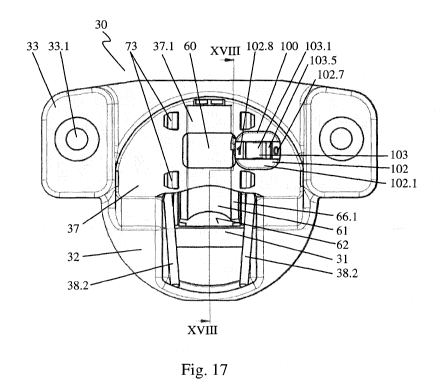
Figure 17 is a plan view of the hinge cup 30 of the furniture hinge 1, as has
already been described with reference to Figures 6 to 9. The locking element
100
is inserted at the side of the linear damper 60 in a recess in the cover 37 of
the
hinge cup 30. In this instance, the locking element 100 abuts with the
abutment
flange 102.1 thereof shown in Figure 15 the edge of the recess on the cover
37.
As a result of the locking attachments 102.6 also shown in Figure 15 on the
locking element housing side walls 102.3, the locking element housing 102 is
secured in the recess of the cover 37. The locking element 100 is orientated
in
such a manner that the rotation axis thereof, as described with reference to
Figure
15, is orientated in the movement direction of the linear damper 60.
Consequently,
the rotation axis is orientated in the direction of the longitudinal extent of
the linear
damper 60 or in the direction of the damping action of the linear damper 60.
In the illustration shown, the locking element 100 is positioned in its
locking
switching position 102.7. The handle 103.5 is consequently pushed in the
direction
toward the region of the abutment flange 102.1 marked with a 0. As a result of
the
locking device 102.9 shown in Figure 15, the locking element 100 is secured
with
respect to unintentional displacement by a user. The handle 103.5 can be
adjusted
in a pivot movement about the rotation axis of the locking element 100 from
the
locking switching position 102.7 into the damping switching position 102.8. In
this
instance, the retention forces applied by the locking device 102.9 are
overcome. In
the damping switching position 102.3, the handle 103.5 abuts the abutment
flange
102.1 at the side marked with a 1. In this position, it is locked by the
locking device
102.9 again. The locking device 102.9 consequently ensures that the locking
switching position 102.7 and the damping switching position 102.8 are in each
32
CA 03064147 2019-07-26
case precisely adjusted and that unintentional displacement of the locking
element
100 by a user is prevented.
When the handle 103.5 is adjusted, the locking element insert 103 is rotated
about
the rotation axis of the locking element 100. The locking bolt 103.3 shown in
Figure 15 is thereby also pivoted about the rotation axis. The locking bolt
103.3
can thus in the locking switching position 102.7 be moved into engagement and
in
the damping switching position 102.8 out of engagement with the blocking
attachment 67 of the linear damper 60. As a result of the orientation of the
rotation
axis of the locking element 100 in the direction of the movement of the linear
damper 60, the locking bolt 103.3 is in this instance pivoted inward and
outward on
a circular path which extends transversely relative to the movement direction
of
the linear damper into the adjustment region of the blocking attachment 67 of
the
linear damper 60. Preferably, the rotation axis is orientated in such a manner
that
the circular path on which the locking bolt 103.3 is moved is orientated
perpendicularly to the movement direction of the linear damper 60. From the
linear
damper 60 and the blocking attachment 67 which is connected thereto, it is
consequently not possible to transmit any force component acting in the
adjustment direction of the locking element 100 to the locking bolt 103.3. It
is
thereby ensured, regardless of the action of the locking device 102.9, that
the
switching position 102.7, 102.8 of the locking element 100 is not adjusted
unintentionally by the action of the linear damper 60. This applies in
particular in
the event of potential wear of the locking device 102.9 with repeated
adjustment of
the locking element 100.
Fig. 18 is a lateral sectioned illustration of the hinge cup 30 shown in
Figure
17.The section path extending at an angle is in this instance illustrated in
Figure
17 and indicated XVIII.
In the illustration selected in Figure 18, the locking element 100 is adjusted
into the
locking switching position 102.7 thereof. The locking bolt 103.3 is
consequently
33
CA 03064147 2019-07-26
pivoted into the adjusted region of the blocking attachment 67. The linear
damper
60 is located in this instance in the inserted position thereof. In the
locking
switching position 102.7 of the locking element 100 and the retracted position
of
the linear damper 60, the locking bolt 103.3 consequently abuts with the
blocking
face 103.6 thereof the blocking counter-face 67.2 of the blocking attachment
67.
The linear damper 60 is thus as a result of accordingly acting restoring
forces with
the furniture hinge 1 open not adjusted into the extended position thereof.
Consequently, the inclination 62 of the cylinder 61 is not pushed into the
centering
region 31 of the hinge cup 30 and consequently the adjustment path of the
articulated lever 43 shown in Figure 14. When the furniture hinge 1 is closed,
the
articulated lever 3 40 consequently does not abut the linear damper 60 over
the
entire adjustment region thereof. The closure movement of the furniture hinge
1 is
therefore not damped by the linear damper 60. The blocking face 103.6 and the
blocking counter-face 67.2 are orientated transversely relative to the
movement
direction of the linear damper 60. As a result of the orientation of the
rotation axis
of the locking element 100 in the movement direction of the linear damper 60,
there is produced an adjustment of the locking bolt 103.3 in the plane of the
blocking face 103.6 and the blocking counter-face 67.2. As a result of the
restoring
forces acting in the direction of the extended position of the linear damper
60 on
the cylinder 61, consequently, no force component acting in the adjustment
direction of the locking bolt 103.3 is transmitted thereto. Depending on the
durability of the locking bolt 103.3 and the blocking attachment 67, the
restoring
forces can consequently be selected to be as large as desired without the
locking
element 100 thereby being unintentionally adjusted from the locking switching
position 102.7 into the damping switching position 102.8 thereof.
By manually adjusting the locking element 100 from the locking switching
position
102.7 into the damping switching position 102.8 thereof, the locking bolt
103.3 is
pivoted out of the adjustment path of the blocking attachment 67. The blocking
attachment 67 and consequently the cylinder 61 of the linear damper 60 are
thereby released. The cylinder 61 can thus with the furniture hinge 1 open be
34
CA 03064147 2019-07-26
adjusted by the acting restoring forces into the extended position thereof.
The
inclination 62 of the cylinder 61 is thereby pushed into the centering region
31 of
the hinge cup 30 and consequently the adjustment path of the articulated lever
43
(see Figure 14). When the furniture hinge 1 is closed, the articulated lever
43
presses in the last movement portion thereof against the inclination 62 of the
linear
damper 60 and pushes it together. The closure movement of the furniture hinge
1
and consequently of the furniture door 5, flap or the like is thereby damped.
In the assembled state, an adjustment of the locking element 100 can be
carried
out only with the furniture door 5, flap or the like open. Starting from a
damping
switching position 102.8 of the locking element 100, the cylinder 61 is first
arranged in the deployed position thereof. When the locking element 100 is
switched from the damping switching position 102.8 thereof into the locking
switching position 102.7 thereof, the locking bolt 103.3 is pivoted at the
side of the
blocking attachment 67 opposite the blocking counter-face 67.2 into the
adjustment path thereof. Consequently, the inclined start-up member 103.4 of
the
locking bolt 103.3 and the attachment inclination 67.1 of the blocking
attachment
67 face each other. When the furniture hinge 1 is closed, the cylinder 61 of
the
linear damper 60 is pushed into the inserted position thereof. In this
instance, the
blocking attachment 67 slides along the attachment inclination 67.1 and the
inclined start-up member 103.4 past the locking bolt 103.3. The locking bolt
103.3
is to this end constructed in a correspondingly resilient manner so that it
can be
displaced by the blocking attachment 67 sliding past by the required distance.
When the inserted end position of the cylinder 61 is reached, the resilient
locking
bolt 103.3 is then adjusted into the tension-free position thereof again so
that the
blocking face 103.6 and the blocking counter-face 67.2 face each other.