Note: Descriptions are shown in the official language in which they were submitted.
CA 03064202 2019-11-19
W0.2018/217490 PCT/US2018/032663
VENTED CONTAINER FOR HOUSING A SCENTED PRODUCT AND
RELATED METHODS
BACKGROUND
[0001] Consumers often face confusion and frustration when trying to
purchase
scented products (e.g., scented trash bags) that are available in a wide
variety of fragrances.
For example, without testing the scented products, the consumer cannot know
whether the
consumer will like the fragrance of the scented product. Some efforts to
remedy the above
problem include scratch and sniff regions included on the packaging of scented
products.
However, the scratch and sniff regions often to not accurately reflect the
fragrance of the
scented products. As a result, consumers can become frustrated (e.g.,
disappointed) when
they do not receive the scented product they expected from the scratch and
sniff regions
[0002] Additionally, scratch and sniff regions are typically relatively
costly to
produce. Furthermore, scratch and sniff regions typically have a very limited
amount of
available fragrance (e.g., a limited number of uses hat provide an accurate
scent).
Accordingly, consumers are often left wondering what the scented product
smells like
because the scratch and sniff region has expired (e.g., been used up).
[0003] Accordingly, there are a number of considerations to be made in
scented
products and the ability to provide consumers an accurate test of a scented
product's
fragrance.
CA 03064202 2019-11-19
W0.2018/217490 PCMS2018/032663
BRIEF SUMMARY
[0004] One or more embodiments of the present disclosure may include a
vented
container for housing a scented product. The vented container can allow a
potential consumer
to selectively experience a scent of the product prior to purchasing or
opening the container.
In one or more embodiments, the container may include a bottom wall, a top
wall, and a
plurality of side walls extending upward from the bottom wall. The bottom
wall, top wall,
and the plurality of side walls defining one or more cavities of the
container. The container
may further include a scented product disposed within one or more cavities
within the
container. The container may further include a plurality of selectively
openable vents
extending through one or more of the walls of the container to the one or more
cavities. The
vents are configured to at least partially open when a force is applied to one
or more of the
walls of the container.
[0005] Further embodiments of the present disclosure include a method of
making a
container for housing a scented product. The method may include forming a
first plurality of
vents in a sheet of material, forming a second plurality of vents in the sheet
of material, and
folding the sheet of material to form a container such that vents of the first
plurality of vents
extend through a first wall of the container and vent of the second plurality
of vents extend
through an opposing wall of the container
[0006] Additional features and advantages of will be set forth in the
description which
follows, and in part will be obvious from the description, or may be learned
by the practice of
such exemplary embodiments. The features and advantages of such embodiments
may be
realized and obtained by means of the instruments and combinations
particularly pointed out
in the appended claims. These and other features will become more fully
apparent from the
following description and appended claims, or may be learned by the practice
of such
exemplary embodiments as set forth hereinafter.
2
CA 03064202 2019-11-19
, W0,2018/217490 PCT/US2018/032663
BRIEF DESCRIPTION OF THE DRAWINGS
[0007] In order to describe the manner in which the above recited and
other
advantages and features of the present disclosure can be obtained, a more
particular
description of the present disclosure briefly described above will be rendered
by reference to
specific embodiments thereof which are illustrated in the appended drawings.
It should be
noted that the figures are not drawn to scale, and that elements of similar
structure or function
are generally represented by like reference numerals for illustrative purposes
throughout the
figures. Understanding that these drawings depict only typical embodiments of
the present
disclosure and are not therefore to be considered to be limiting of its scope,
the present
disclosure will be described and explained with additional specificity and
detail through the
use of the accompanying drawings in which:
[0008] FIG. 1 shows a perspective view of a container for housing a
scented product
according to an embodiment of the present disclosure;
[0009] FIG. 2A shows a cross-sectional side view of a container housing a
scented
product according to an embodiment of the present disclosure;
[0010] FIG. 2B shows a cross-sectional side view of the container of FIG.1
with a
vent of the container in an open position according to an embodiment of the
present
disclosure;
[0011] FIG. 2C shows a cross-sectional side view of the container of FIG.1
with a
vent of the container in an open position according to another embodiment of
the present
disclosure;
[0012] FIG. 3A is a partial cross-sectional side view of a top wall of a
container with
a vent extending there through according to an embodiment of the present
disclosure;
3
CA 03064202 2019-11-19
' W01018/217490
PCT/US2018/032663
[0013] FIG. 3B
is a partial cross-sectional side view of a top wall of a container with
a vent extending there through according to an embodiment of the present
disclosure;
[0014] FIG. 3C
is a partial cross-sectional side view of a top wall of a container with
a vent extending there through according to an embodiment of the present
disclosure;
[0015] FIG. 3D
is a partial cross-sectional side view of a top wall of a container with
a vent extending there through according to an embodiment of the present
disclosure;
[0016] FIG. 3E
is a partial cross-sectional side view of a top wall of a container with
a vent extending there through according to an embodiment of the present
disclosure;
[0017] FIG. 4A
is a cross-sectional side view of a container having a first vent
extending through a top wall of the container and a second vent extending
through a bottom
wall of the container according to another embodiment of the present
disclosure;
[0018] FIG. 4B
is a cross-sectional side view of the container of FIG. 4A with the
first vent and the second vent in open positions;
[0019] FIG. 5
shows a perspective view of a container for housing a scented product
according to another embodiment of the present of the present disclosure;
[0020] FIGS. 6A-
6H show perspective views of containers for housing scented
products according to additional embodiments of the present disclosure; and
[0021] FIG. 7
shows flow diagram of a method of making a container for housing a
scented product according to one or more embodiments of the present
disclosure.
4
RECTIFIED SHEET (RULE 91)
CA 03064202 2019-11-19
W0.2018/217490 PCT/US2018/032663
DETAILED DESCRIPTION
[0022] One or more embodiments of the present disclosure include a
container (e.g., a
carton or packaging) for housing a scented product (e.g., scented trash bags)
that allows users
(e.g., consumers) to accurately test (e.g., try out) an actual fragrance of
the scented product
disposed within the container without opening the container. For example, the
container
allows users to test out a fragrance of the scented product while at a store
prior to purchasing
the scented product.
[0023] In some embodiments, the container includes one or more
selectively openable
and closable vents extending through one or more walls of the container. For
example, the
container may include the one or more vents extending through a first wall of
the container.
Furthermore, applying a force to the container may open the one or more of
vents. For
instance, a user can open the one or more vents by squeezing the container.
Moreover, by
squeezing the container, the user may cause a puff of fragrance to pass
through the one or
more vents allowing the user to test (e.g., sniff) the fragrance of the scent
product.
[0024] In one or more embodiments, the container includes a first
selectively
openable and closable vent extending through a first wall of the container and
a second
selectively openable and closable vent extending through an opposing wall of
the container.
Furthermore, similar to the one or more vents mentioned above, applying a
force to the
container may open both the first vent and the second vent. In particular, a
user can open the
both the first and the second vents by squeezing the container. Moreover, by
opening both the
first and the second vents, air may be permitted to enter the container
through the second
vent, pass over the scented product, and escape the container through the
first vent. As a
result, when a user sniffs the container, the user may experience a more
potent amount of the
fragrance of the scented product allowing to user to more accurately test the
fragrance of the
scented product.
CA 03064202 2019-11-19
' W02018/217490 PCT/1JS2018/032663
[0025] Because the container allows a user to test the fragrance of the
scented
product, the container of the present disclosure is advantageous over
conventional containers
for housing scented products (e.g., scratch and sniff containers). For
instance, unlike
conventional scratch and sniff containers, which often do not accurately
reflect the actual
fragrance of the scented product inside of the container, the selectively
openable and closable
vent(s) of the container enables a user to accurately test the fragrance of
the scented product
prior to purchasing the scented product. Thus, the selectively openable and
closable vent(s) of
the container enable a user to find a scented product to the user's liking.
[0026] Furthermore, as will be readily recognized by one of ordinary
skill in the art,
by enabling a user to accurately find a fragrance to the user's liking (e.g.,
helping the user
discover something that the user likes about the product), the selectively
openable and
closable vent(s) of the present disclosure will help encourage users to
purchase the scented
product, thus leading to additional sales and revenue. Moreover, by allowing a
user to test
fragrances of scented products, the container of the present disclosure is
more likely to entice
(e.g., persuade, encourage, etc.) a user to handle (e.g., interact with) the
container (e.g., pick
up the container off of a shelf at a store) and test the fragrance.
Additionally, increased
interaction with a product increases a likelihood that the user will purchase
the product.
[0027] In comparison to conventional containers, which are costly to
produce and
which provide a relatively limited amount of available fragrance (i.e., a
limited number of
uses), the container of the present disclosure reduces cost by not having
scratch and sniff
regions and provides more available fragrance to test. Specifically, because a
user is smelling
the actual scented product instead of a scratch and sniff region, the
available fragrance of the
container of the present disclosure lasts longer than conventional containers
and provides a
more accurate sample of the actual fragrance of the scented product.
6
CA 03064202 2019-11-19
WO 2018/217490 PCT/US2018/032663
[0028] As used herein, the term "substantially" in reference to a given
parameter,
property, or condition means and includes to a degree that one skilled in the
art would
understand that the given parameter, property, or condition is met with a
small degree of
variance, such as within acceptable manufacturing tolerances. For example, a
parameter that
is substantially met may be at least about 90% met, at least about 95% met, or
even at least
about 99% met.
[0029] As used herein, any relational terms such as "first," "second," and
"third,"
"interior," "exterior," "top," "bottom," "upward," etc. are for clarity and
convenience in
understanding the present disclosure and accompanying drawings and does not
connote or
depend on any specific preference, orientation, or order, except where the
context clearly
indicates otherwise. For example, the relational terms may refer an
orientation of a container
for housing a scented material while disposed on a planar horizontal surface
(e.g., a store
shelf).
[0030] FIG. 1 shows a container 100 (e.g., carton or box) for housing a
scented
product. The container 100 is illustrated with a portion removed to better
shown internal
elements of the container 100. The container 100 may include a bottom wall
102, a top wall
104, a plurality of lateral sidewalls 106, 108, a plurality of longitudinal
sidewalls 110, 112, a
first plurality of vents 114, a second plurality of vents 116, and a
perforated opening 117. The
plurality of lateral sidewalls 106, 108 may be disposed on lateral sides of
the bottom wall 102
and the top wall 104, and the plurality of longitudinal sidewalls 110, 112 may
be disposed on
longitudinal sides of the bottom wall 102 and the top wall 104. Furthermore,
the plurality of
longitudinal sidewalls 110, 112 and the plurality of lateral sidewalls 106,
108 may extend
upward from the bottom wall 102 and may, in conjunction with the bottom wall
102 defined
a cavity 118 within the container 100. For example, the plurality of
longitudinal sidewalls
106, 108 and the plurality of lateral sidewalls 110, 112 may extend between
the bottom wall
7
CA 03064202 2019-11-19
' W02018/217490 PCT/US2018/032663
102 and the top wall 104. Additionally, in one or more embodiments, a scented
product (e.g.,
trash bags) (FIG. 2A) may be disposed within the cavity 118 of the container
100.
Furthermore, the container 100 may include a perforated opening 117 extending
through the
top wall 104 of the container and that may be opened to allow a user to remove
the scented
product and/or portions of the scented product from the container 100.
[0031] The first plurality of vents 114 (e.g., slits, holes, apertures,
indentions, etc.)
may extend through one or more walls. For example, FIG. 1 illustrates an
embodiment in
which the first plurality of vents 114 extend through the top wall 104. In
some embodiments,
the first plurality of vents 114 may extend completely (e.g., entirely)
through the wall in
which they are formed (e.g., from an exterior surface 120 to an interior
surface). In other
embodiments, the first plurality of vents 114 may extend only partially
through the wall in
which they are formed. In such embodiments, the first plurality of vents 114
may extend at
least substantially the wall in which they are formed.
[0032] The second plurality of vents 116 may extend through a wall
opposite the wall
in which the first plurality of vents 114 extend. For example, FIG. 1
illustrates the second
plurality of vents 116 extending through the bottom wall 102. In some
embodiments, the
second plurality of vents 116 may extend completely (e.g., entirely) through
the wall in
which they are formed (e.g., from an exterior surface to an interior surface).
In other
embodiments, the second plurality of vents 116 may extend only partially
through the wall in
which they are formed. In such embodiments, the second plurality of vents 116
may extend at
least substantially through the wall in which they are formed.
[0033] In one or more embodiments, the first plurality of vents 114 may
be disposed
proximate to longitudinal ends of the container 100. For example, the first
plurality of vents
114 may extend through the top wall 104 at a region and/or regions of the top
wall 104
proximate the longitudinal ends of the container 100. In other embodiments,
the first plurality
8
CA 03064202 2019-11-19
WO 2018/217490 PCT/US2018/032663
of vents 114 may be disposed proximate to a center region of the container
100. For instance,
the first plurality of vents 114 may extend through the top wall 104 at a
region of the top wall
104 proximate the center of the container 100. Similarly, the second plurality
of vents 116
may be disposed proximate to the longitudinal ends of the container 100 in the
same manners
described above. In any event, in one or more embodiments, the vents are
positioned to be at
a point of maximum deflection of the container when a force is applied. For
example, the
container can be configured such that when squeezed, the middle of a wall of
the container
defects more than the sides or edges. The vents can be positioned at the point
of maximum
deflection of the container to help ensure that the vents open when the proper
force is applied
to the container.
[0034] Furthermore, although the first and second plurality of vents 114,
116 are
illustrated in FIG. 1 as extending in a longitudinal direction (e.g., in a
direction parallel to a
longitudinal axis of the container 100), the disclosure is not so limited, and
the vents of the
first and second plurality of vents 114, 116 may extend in any direction.
[0035] To facilitate explanation of the present disclosure, the first
plurality of vents
114 and second plurality of vents 116 may be referred to herein collectively
as "the plurality
of vents 114, 116". In some embodiments, each vent of the plurality of vents
114, 116 may be
selectively openable and closable to permit a user to test (e.g., sniff) a
fragrance of the
scented product within the container. In particular, as will be discussed in
greater detail
below, the plurality of vents 114, 116 may be selectively opened by applying
force to the
container (e.g., the longitudinal 110, 112 and/or lateral sidewalls 106, 108).
The plurality of
vents 114, 116 may be selectively closed by removing the force from the
sideWalls (e.g.,
releasing the container). As a non-limiting example, during use, the plurality
of vents 114,
116 may open when a user (i.e., a consumer) squeezes the container 100, and
the plurality of
vents may close when the user releases the container 100. Operation of the
plurality of vents
9
CA 03064202 2019-11-19
WO 2018/217490 PCT/US2018/032663
114, 116 is described in greater detail below in regard to FIGS. 2A-4B. In
alternative
embodiments, each vent of the plurality of vents 114, 116 may include an
aperture extending
through a wall of the container 100. For example, the plurality of vents 114,
116 may be
permanently open. In further embodiments, each vent of the plurality of vents
114, 116 may
include an aperture extending through a wall of the container 100 and a porous
and/or
breathable material disposed within the aperture such that fluids (e.g., air)
can pass through
the aperture and through the porous and/or breathable material. In some
instances, the porous
and/or breathable material can include materials having micro perforations
such as TYVEK
and/or GORTEX.
[0036] In one or more embodiments, the scented product may include one or
more of
scented trash bags, wraps, grocery bags, sacks, packaging materials, feminine
hygiene
products, baby diapers, adult incontinence products, or other products.
Furthermore, the
product may be scented with odor control components, such as, one or more of
volatile
fragrance materials (i.e., fragrance materials capable of being transported to
the olfactory
system) and deodorizing agents (e.g., deodorizing compositions with a
deodorizing effect on
offensive odors such as that associated with activated nitrogen compound,
activated sulfur
compounds, etc.). As used herein the term "fragrance" refers to any mixture or
composition
comprising one or more perfume raw materials with or without one or more
carrier solvents
configured to emit a pleasant odor. Moreover, as used herein the term
"perfume" refers to a
compound utilized for its appealing odor. Compounds may have a pleasing odor
without
being used as a perfume in the context of this disclosure. Furthermore, the
scent of the
perfume may be designed to indicate a functional benefit such as freshness or
cleanliness. For
example, in some embodiments, the scent may smell similar to bleach,
antiseptic, and/or
flavors.
CA 03064202 2019-11-19
WO 2018/217490 PCT/US2018/032663
[0037] In one or more instances, the container 100 may include (e.g., be
made of) one
or more of containerboard, folding boxboard, solid bleached board, solid
unbleached board,
white lined chipboard, binder's board, corrugated fiberboard, or other
materials. In additional
embodiments, the container may include one or more polymers such as Polyester
(PES),
Polyethylene terephthalate (PET), Polyethylene (PE), High-density polyethylene
(HDPE),
Polyvinyl chloride (PVC), Polyvinylidene chloride (PVDC), Low-density
polyethylene
(LDPE), Polypropylene (PP), Polystyrene (PS), High impact polystyrene (HIPS),
and
Polyamides (PA).
[0038] Furthermore, although the container 100 is described in regard to
FIG. 1 as
having a general rectangular shape, the disclosure is not so limited. Rather,
the container 100
may have any shape defining at least one cavity therein. For example, the
container 100 may
have a spherical shape, a canister/cylinder shape, a bottle shape, or any
other shape.
[0039] FIG. 2A shows a cross-sectional longitudinal side view of a
container 200
according to one or more embodiments of the present disclosure. Specifically,
the plane
defined by FIG. 2A is parallel to a longitudinal sidewall of the container
200. Additionally,
elements of FIG. 2A (e.g., thicknesses of the walls of the container 200) may
be exaggerated
for clarity. Similar to the container 100 of FIG. 1, the container 200
includes a top wall 204, a
bottom wall 202, lateral sidewalls 206, 208, longitudinal sidewalls (FIG. 1),
a scented product
222 disposed within a cavity 218 of the container 200, and a vent 214
extending through the
top wall 204 of the container 200. The container 200 is illustrated with only
one vent 214 for
clarity and to facilitate explanation of the operation of the vent 214.
However, it is
understood that the container 200 may contain a plurality of vents.
[0040] The vent 214 is illustrated in a closed position (i.e., as closed)
in FIG. 2A.
When closed, the vent 214 (and the surrounding container 200) may at least
substantially
prevent air from escaping the container 200 and/or entering the container 200.
For example,
11
CA 03064202 2019-11-19
WO 2018/217490 PCT/US2018/032663
when closed, the vent 214 may at least substantially prevent airflow through
the vent 214. As
a result, the vent 214 may at least substantially prevent a fragrance (e.g.,
fragrance particles)
of the scented product 222 from escaping the container 200. By preventing air
and/or
fragrance particles from leaving the container 200 and airflow entering into
the container
when closed, the vent 214 may assist in maintaining a fragrance of the scented
product 222
(i.e., may prevent fragrance loss).
[0041] In some embodiments, the vent 214 can have a general triangle
shape.
Specifically, the vent 214 may define a general triangular prism shape with a
side (e.g., a
planar side) of the triangular prism shape being coplanar with an exterior
surface 220 of the
top wall 204 and a corner edge of the triangular prism shape opposite the side
(e.g., a point of
a cross-sectional triangle of the triangular prism) intersecting a plane
defined by the interior
surface 224 of the top wall. Described differently, the vent 214 may include a
V-shaped
channel in the top wall 204. For instance, the channel may extend into the top
wall 204 from
the exterior surface 220, and a bottom (i.e., a point) of the channel may
intersect the plane
defined by the interior surface 224 of the top wall 204. Described yet another
way, the vent
214 may be defined by two opposing wedge ends formed in the top wall. Narrow
ends (e.g.,
the thin ends) of the two opposing wedge ends may contact each other when the
vent is
closed. The vent's shape is described in further detail below in regard to
FIGS. 3A-3E.
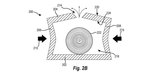
[0042] FIG. 2B shows a cross-sectional side view of the container 200 of
FIG. 2A
with the vent 214 in an open position. In operation, as noted above, the vent
214 of the
container 200 can be opened by applying force (represented by arrow 215) to
one or more of
the lateral sidewalls 206, 208 and longitudinal sidewalls (FIG. 1) of the
container 200. For
example, as illustrated in FIG. 2B, the vent 214 of the container 200 can be
opened when
force 215 is applied to the lateral sidewalls 206, 208 of the container 200.
Specifically, when
force 215 is applied to the lateral sidewalls 206, 208 of the container 200,
the lateral sidewalls
12
CA 03064202 2019-11-19
WO 2018/217490 PCT/US2018/032663
206, 208 may flex (e.g., bend, bow, etc.), which causes the top wall 204 to
also flex, which,
in turn, causes the vent 214 to at least partially open. For example, due to
the lateral sidewalls
206, 208 flexing, the top wall 204 may bow outward (i.e., away from a center
of the
container), which causes the vent 214 to at least partially open. For
instance, due to the top
wall 204 flexing, the portions of the top wall 204 (e.g., the opposing wedge
ends) defining the
vent 214 may at least partially separate causing the vent 214 to open.
[0043] In alternative embodiments, the vent 214 of the container 200 can
be opened
by applying force 215 to one or more of the top wall 204 and a bottom wall 202
of the
container 200. In further embodiments, the vent 214 may also be at least
partially opened due
to increased pressure within the cavity 218 of the container 200 caused by the
force 215
applied to the lateral sidewalls 206, 208 of the container 200. For instance,
when the force
215 is applied to the lateral sidewalls 206, 208 of the container 200 (i.e., a
user squeezes the
container), the lateral sidewalls 206, 208 may bow toward a center of the
container 200 (i.e.,
inward) causing a pressure (e.g., an air pressure) within the cavity 218 of
the container 200 to
increase and may, in turn, cause the vent 214 to at least partially open to
permit airflow
through the vent 214 (i.e., to relieve the pressure within the cavity 218).
[0044] In some embodiments, the shape of the vent 214 may increase a
likelihood that
the vent will open when force 215 is applied to the container 200 (i.e., when
the container
200 is squeezed). As discussed above, the vent 214 may be closed when narrow
ends of
opposing wedge ends contact each other. As a result, to open the vent 214,
only the narrow
ends of the opposing wedge ends need to be separated. For instance, less
contacting surfaces
need to be separated in order to open the vent 214 of the present disclosure
in comparison to,
for example, two opposing square ends (i.e., ends having parallel end
surfaces), which would
have the entire end surfaces contacting each other when closed. As noted
above, the shape of
the vent 214 is described in further detail in regard to FIGS. 3A-3F.
13
CA 03064202 2019-11-19
WO 2018/217490 PCT/US2018/032663
[0045] When the vent 214 is open (i.e., in an open position), the vent may
permit air
from within the container 200 to escape through the vent. For example, when
the vent 214 is
open, air from within the container 200 may pass through the vent 214.
Furthermore, because
a user squeezes the container to cause the vent 214 to open, increased
pressure within the
container 200 may cause at least some air to pass through the vent 214 (e.g.,
a puff of air
through the vent 214). Moreover, the air escaping from the container 200 may
include
fragrance particles (e.g., may be scented) from the scented product 222. As a
result, because
the air is scented, a fragrance of the scented product 222 may be tested
(e.g., smelled) by a
user (e.g., a consumer). For instance, when the vent is open, the user may
smell the scented
product 222 disposed within the container 200.
[0046] By allowing a user to test the fragrance of the scented product
222, the
container 200 of the present disclosure is advantageous over conventional
containers of
scented products. For example, unlike conventional containers that allow a
user to test a
fragrance (e.g., scratch and sniff containers), which often do not accurately
reflect the actual
fragrance of the scented product inside of the container, the container 200 of
the present
disclosure enables a user to accurately test (e.g., tryout) the fragrance of
the scented product
222 prior to purchasing the scented product 222. Furthermore, by enabling a
user to
accurately test the fragrance of the scented product 222, the container 200 of
the present
disclosure enables a user to experiment with different scented products to
discover (e.g., find)
a scented product to the user's liking.
[0047] Additionally, because the vent 214 of the container 200 of the
present
disclosure can be selectively opened and closed by a user, the container 200
provides
additional advantages over conventional containers. Specifically, because the
vent 214 does
not open until a force is applied to the sidewalls (e.g., longitudinal and/or
lateral sidewalls
206, 208) of the container 200, the vent 214 may remain closed (e.g., at least
substantially
14
CA 03064202 2019-11-19
WO 2018/217490 PCT/US2018/032663
sealed) while the container 200 is not being manipulated, for example, while
the container
200 is stationary on shelf of a store. In one or more embodiments, the vents
are sized and
configured to resist opening when subjected to forces typically associated
with handling of a
container (stocking, shipping, etc.). Along related lines, the container 200
protects the
scented product 222 from airflow that may be caused by users (e.g., consumers)
passing
down aisles of a store. As a result of the foregoing, the container 200, even
when housing the
scented product 222, will not fill an aisle with the fragrance of the scented
product 222 and
alienate users (e.g., consumers) who do not want scented products 222.
[0048] Likewise, because the vent 214 will only open when manipulated by a
user
(e.g., squeezed by a user), the container 200 may maintain a fragrance of the
scented product
222 in comparison to containers that have permanent apertures and/or
permanently opened
vents. In particular, in one or more embodiments, the vents are sized and
configured to open
when a force (e.g., a user squeezes the container) is applied that is greater
than the forces
typically associated with handling of a container (e.g., stocking or
shipping). Thus, the vents
of the container reduce fragrance lost by (i.e., a fragrance loss of) outer
portions of the
scented product 222. Moreover, because the vent 214 is selectively openable,
the container
200 permits a user to selectively test different scented products within
different containers.
[0049] Referring still to FIG. 2B, in one or more embodiments, a number of
vents 214
(e.g., a number of vents included in the first and second pluralities of vents
114, 116 (FIG. 1))
may be controlled in order to allow for a sufficient fragrance release (e.g.,
enough fragrance
so that a typical user can smell the fragrance) but avoiding noticeable
fragrance loss to the
scented product 222. For example, in some embodiments, the first and second
pluralities of
vents 114, 116 (FIG. 1) may each include two, three, five, ten, or more vents.
[0050] As noted above, in some embodiments, the vent 214 may not extend
completely through the top wall 204 of the container 200. In such embodiments,
a portion of
CA 03064202 2019-11-19
WC) 2018/217490 PCT/US2018/032663
the top wall 204 remaining at the vent 214 (i.e., the amount of the top wall
204 through which
the vent 214 does not extend) may be sufficiently thin such that when a user
squeezes the
container 200, the portion breaks such that the vent 214 becomes selectively
openable and
closable. By forming the vent 214 such that the vent 214 does not extend
completely through
the top wall 204 of the container 200 originally, the vent 214 may further
prevent fragrance
loss during, for example, shipping and shelf time prior to first being tested
by a user. The
foregoing may result in yet less fragrance loss in comparison to conventional
containers.
[0051] In one or more embodiments, how the vent 214 of the container 200
opens is
dependent on where the force 215 is applied to the container 200 (e.g., where
the container
200 is squeezed by the user). For example, FIG. 2C shows a cross-sectional
view of the
container 200 of FIG. 2B with the vent 214 open according to another
embodiment of the
present disclosure. As illustrated in FIG. 2C, in some instances, in response
to a force 215
being applied to sidewalls (e.g., the lateral sidewalls 206, 208 and/or
longitudinal sidewalls
(FIG. 1)), the top wall 204 of the container 200 may bow inward instead of
outward, which
also causes the vent 214 to at least partially open. For example, in some
cases, the closer to
the top wall 204 the force 215 is applied on the sidewalls, the more likely
the top wall 204 is
to bow inward instead of outward. Furthermore, as noted above, in some
instances, the force
215 may be applied to the top wall 204, and as a result, the top wall 204 may
bow inward and
may cause the vent 214 to at least partially open. Specifically, due to the
top wall 204 bowing
(i.e., flexing), the portions of the top wall 204 (e.g., the opposing wedge
ends) defining the
vent 214 may at least partially separate causing the vent 214 to open.
[0052] Referring to FIGS. 1-2C together, in additional embodiments, each
vent of the
plurality of vents 114, 116 may include a one-way vent (e.g., a one-way
valve). In other
words, each vent of the plurality of vents 114, 116 may generally allow fluids
(e.g., air) to
flow through the vent 114 in only one direction. In such embodiments, the
first plurality of
16
CA 03064202 2019-11-19
W02018/217490 PCT/US2018/032663
vents 114 may allow air to flow out of the container 200, and the second
plurality of vents
116 may allow air to flow into the container 200, as will be discussed in
greater detail in
regard to FIGS. 4A and 4B.
[0053] FIGS. 3A-3E illustrate various types of vents of a container 300
according to
various embodiments of the present disclosure. For example, FIG. 3A
illustrates a vent 314a
according to another embodiment of the present disclosure. The vent 314a may
include two
opposing wedge ends with narrow ends of the opposing wedge ends contacting
each other.
The narrow ends (e.g., the points) of the opposing wedge ends, when the vent
314a is in a
closed position, may intersect a central plane of the top wall 304, and the
central plane may
extend between the exterior surface 320 of the top wall 304 and the interior
surface 324 of the
top wall 304 and may be parallel to the exterior surface 320 and interior
surface 324 of the
top wall 304. Put another way, the vent 314a may have an at least general
hourglass shaped
cross-section.
[0054] The vent 14a illustrated in FIG. 3A may facilitate the vent 314a
opening both
ways (e.g., bowing inward and outward, as describe above in regard to FIGS. 2B
and 2C)
with equal amounts of force 215 (FIG. 2B). For example, the vent 314a may be
as likely to
open inward as the vent 314a is to open outward. As a result, the vent 314a
may maximize a
likelihood that the vent 314a will open when a force 215 (FIG. 2B) is applied
to the sidewalls
of the container 300 regardless of where the force 215 (FIG. 2B) is applied on
the sidewalls.
[0055] FIG. 3B illustrates a vent 314b according to another embodiment of
the
present disclosure. The vent 314b may be similar to the vent 214 described in
regard to FIG.
2A. For example, the vent 314b can include (e.g., have) a general triangle
shape and may
define a triangular prism shape with a side of the triangular prism shape
being coplanar with
an interior surface 324 of the top wall 304 and a corner edge of the
triangular prism shape
opposite the side intersecting a plane defined by an exterior surface 320 of
the top wall 304.
17
CA 03064202 2019-11-19
WO 2018/217490 PCT/US2018/032663
Put another way, the vent 314b can include a V-shaped channel in the top wall
304, where the
channel extends into the top wall 304 from the interior surface 324, and where
a bottom (i.e.,
a point) of the channel intersects the plane defined by the exterior surface
320 of the top wall
304.
[0056] In some embodiments, the vent 314b illustrated in FIG. 3B may be
utilized to
make the vent 314b less visible from an exterior of the container 300.
Specifically, the vent
314b may include the same functionality as the vent 214 described above in
regard to FIG.
2A but may, in some instances, be more aesthetically pleasing because the vent
314b may be
less noticeable from an exterior of the container 300.
[0057] FIG. 3C illustrates a vent 314c according to another embodiment of
the
present disclosure. The vent 314c may include two opposing curved surfaces
326a, 326b with
the peaks of the two opposing curved surfaces 326a, 326b contacting each other
when the
vent 314c is closed. Furthermore, the peaks of the two opposing curved
surfaces 326a, 326b,
when in a closed position, may intersect the central plane of the top wall
304. Moreover, the
vent 314c may maximize a likelihood that the vent 314c will reseal after being
opened.
Specifically, because the vent 314c is defined by two opposing curved surfaces
326a, 326b,
the vent 314c may include more viable surfaces with which to seal than the
narrow ends of
wedges.
[0058] FIG. 3D illustrates a vent 314d according to another embodiment of
the
present disclosure. As shown, the vent 314d may be defined by two sets of
opposing wedges
332, 334 defining an at least generally rectangular shaped prism void
extending through the
top wall in a direction parallel to the exterior surface 320 of the top wall
304. Each set of the
opposing wedges 332, 334 includes two opposing wedges with narrow ends of the
two
opposing wedges contacting each other. The narrow ends of a first set of the
opposing
wedges 332 may intersect a plane defined by the interior surface 324 of the
top wall 304, and
18
CA 03064202 2019-11-19
WO 2018/217490 PCT/US2018/032663
the narrow ends of a second set of the opposing wedges 334 may intersect a
plane defined by
the exterior surface 320 of the top wall 304. Furthermore, the vent 314d
increases a
likelihood that the vent 314d will reseal after being open. Specifically,
because the vent 314d
includes two sets of opposing wedges 332, 334, the vent 314d includes two sets
of narrow
ends, and therefore, includes more surfaces with which the vent 314d can
reseal. For
example, the vent 314d includes double the surface area for resealing in
comparison to the
vent 214 described in regard to FIG. 2A, and therefore, is more likely to
reseal after being
opened.
[0059] FIG. 3E illustrates a vent 314e according to another embodiment of
the
present disclosure. As shown, the vent 314e is be defined by a square end 336
and a wedge
end 338. Furthermore, when in a closed position, a narrow end of the wedge end
338 contacts
the square end 336 of the vent 314e. Moreover, the vent 314e includes an
increased amount
of available surface area for resealing (i.e., the entire end surface of the
square end 336 in
comparison to a mere narrow end of a wedge end) while having a same amount of
actual
contacting surface areas (i.e., the narrow end of the wedge end 338 contacting
the square end
336) as the vent 214 described in regard to FIG. 2A. As result, the vent 314e
increases a
likelihood of resealing while maintaining a likelihood that the vent 314e will
open.
[0060] As noted above in regard to FIG. 1, in some embodiments, the
container 100
can include a first plurality of vents 114 extending through a first wall of
the container 100
and a second plurality of vents 116 extending through an opposing wall of the
container 100.
For example, FIG. 4A illustrates a cross-sectional side view of a container
400 having a first
vent 414a extending through a top wall 404 of a container 400 and a second
vent 414b
extending through a bottom wall 402 of the container 400 according to an
embodiment of the
present disclosure. In particular, the first vent 414a is similar to the vent
214 described above
in regard to FIG. 2A. For example, the first vent 414a includes a general
triangular prism
19
CA 03064202 2019-11-19
WO 2018/217490 PCT/US2018/032663
shape with a side of the triangular prism shape being coplanar with an
exterior surface 420 of
the top wall 404 and a corner edge of the triangular prism shape opposite the
side intersecting
a plane defined by the interior surface 424 of the top wall 404. Put another
way, the first vent
414 can include a V-shaped channel in the top wall 404, where the channel
extends into the
top wall 404 from the exterior surface 420, and where a bottom (i.e., a point)
of the channel
intersects the plane defined by the interior surface 424 of the top wall 404.
In additional
embodiments, the first vent 414a may include any of the types of vents
described above in
regard to FIGS. 3A-3E.
[0061] Additionally, the second vent 414b is also similar to the vent 214
described
above in regard to FIG. 2A. For example, the second vent 414b includes a
general triangular
prism shape with a side of the triangular prism shape being coplanar with an
exterior surface
420 of the bottom wall 402 and a corner edge of the triangular prism shape
opposite the side
intersecting the plane defined by the interior surface 424 of the bottom wall
402. Put another
way, the second vent 414b can include a V-shaped channel in the bottom wall
402, where the
channel extends into the bottom wall 402 from the exterior surface 420, and
where a bottom
(i.e., a point) of the channel intersects the plane defined by the interior
surface 424 of the
bottom wall 402. In additional embodiments, the second vent 414b may include
any of the
types of vents described above in regard to FIGS. 3A-3E.
[0062] In one or more embodiments, the first vent 414a and the second
vent 414b
may include the same types of vents (e.g., the embodiment illustrated in FIG.
4A). In
additional embodiments, the first vent 414a may include a first type of vent
(e.g., the type of
vent illustrated in FIG. 2A) and the second vent 414b may include a second
different type of
vent (e.g., the type of vent illustrated in FIG. 3A).
[0063] FIG. 4B shows a cross-sectional side view of the container 400 of
FIG. 4A
with the first vent 414a and the second vent 414b in open positions. Similar
to the vent 214
CA 03064202 2019-11-19
W02018/217490 PCT/US2018/032663
described above in regard to FIG. 2B, the first vent 414a and the second vent
414b can be
opened by applying force 415 to one or more of the lateral sidewalls 406, 408
and
longitudinal sidewalls of the container 400. For example, as illustrated in
FIG. 4B, the first
vent 414a and the second vent 414b of the container 400 can be opened when
force 415 is
applied to the lateral sidewalls 406, 408 of the container 400. Specifically,
when force 415 is
applied to the lateral sidewalls 406, 408 of the container 400, the lateral
sidewalls 406, 408
may flex (e.g., bend, bow, etc.), which causes the top wall 404 and the bottom
wall 402 to
also flex (e.g., bow outward), which, in turn, causes the first vent 414a and
the second vent
414b to at least partially open. For instance, due to the top wall 404
flexing, the portions of
the top wall 404 defining the first vent 414a may at least partially separate
causing the first
vent 414a to open. Similarly, due to the bottom wall 402 flexing, the portions
of the bottom
wall 402 defining the second vent 414b may at least partially separate causing
the second
vent 414b to open. As a non-limiting example, in use, the first vent 414a and
the second vent
414b may open when a user squeezes the container 400, as described above.
[0064] When the first vent 414a and the second vent 414b of the container
400 are
open, as illustrated in FIG. 4B, the first vent 414a and the second vent 414b
may permit air to
enter into the container 400 via one of the vents (e.g., the second vent
414b), pass over the
scented product 422, and exit the container 400 through the other vent (e.g.,
the first vent
414a). Specifically, in use, when a user squeezes the container 400 to open
the first and
second vents 414a, 414b and sniffs the container 400 proximate to the first
vent 414a, the act
of sniffing may cause air to pass through the container 400 (i.e., through the
first and second
vents 414a, 414b), pass over the scented product 422, pick up fragrance
particles from the
scented product 422, and enter the user's olfactory system such that the user
can smell the
scented product 422.
21
CA 03064202 2019-11-19
WO 2018/217490 PCT/US2018/032663
[0065] In addition to allowing air to flow over the scented product 422
and permitting
a user to smell the scented product 422, placing the first vent 414a (or first
plurality of vents)
in the top wall 404 and the second vent 414b (or second plurality of vents) in
the bottom wall
402 may minimize fragrance loss in comparison to placing the first and second
vents 414a,
414b in a sidewall of the container 400. For example, the bottom wall 402 of
the container
400 will typically be in contact with a store shelf or another container
(e.g., another carton of
trash bags), and thus, the second vent 414b in the bottom wall 402 will be
shielded from most
airflow, which can cause fragrance loss, while in contact with the store shelf
and/or another
container. Furthermore, the top wall 404 of the container 400 will typically
be in contact with
another container or, at least, will typically not directly face an aisle
where users walk past
causing airflow, and thus, will typically not be exposed to coincidental
airflow caused by
users. As a result, the top wall 404 of the container 400 also avoids most
airflow except when
being handled by a user.
[0066] In view of the foregoing, because the placement of the first vent
414a and the
second vent 414b helps to minimize exposure to airflow, the container 400 of
the present
disclosure may minimize fragrance loss of the scented product 422.
Specifically, because an
exposure of the first vent 414a and the second vent 414b is minimized, airflow
into and out of
the container 400 is minimized, and because airflow into and out of the
container 400 is
minimized, the fragrance (i.e., fragrance particles) of the scented product
422 remains within
the container 400.
[0067] FIG. 5 illustrates a container 500 for housing a scented product
according to
another embodiment present disclosure. Similar to the container 100 described
above in
regard to FIG. 1, the container 500 includes a bottom wall 502, a top wall
504, a plurality of
lateral sidewalls 506, 508, a plurality of longitudinal sidewalls 510, 512, a
first plurality of
vents 514, and a perforated opening 517. Additionally, similar to the
container 100 of FIG. 1,
22
CA 03064202 2019-11-19
WO 2018/217490 PCT/US2018/032663
the first plurality of vents 514 may extend through the top wall 504 of the
container 500. In
addition to the first plurality of vents 514, the container 500 includes one
or more designated
regions 530 (e.g., thumbprints) indicating to a user where to apply force 215
(FIG. 2B) to
(e.g., squeeze) the container 500 in order to test (e.g., smell) the fragrance
of the scented
product 222 (FIG. 2A). Moreover, in some embodiments, the container 500 may
include a
second plurality of vents 116 (FIG. 1) extending through the bottom wall 502
of the container
500.
[0068] As illustrated, in some instances, the first plurality of vents
514 may be
oriented relative to one another in a pattern. For example, the first
plurality of vents 514 may
be oriented in a pattern representing a fragrance of the scented product 222
(FIG. 2A)
disposed within a cavity 118 (FIG. 1) of the container 500. Specifically, the
first plurality of
vents 514 may be oriented in a shape of one or more of a cloud, a flower, a
Hawaiian aloha, a
sunburst, a fruit, a vegetable, a plant, a leaf, or any other shape
representing a fragrance.
Furthermore, the first plurality of vents 514 may include any of the types of
vents described
above in regard to FIGS. 2A-3E.
[0069] As noted above, the container 500 may also include one or more
designated
regions 530 indicating to the user where to apply force 215 (FIG. 2B) to
(e.g., squeeze) the
container 500. In some embodiments, the one or more designated regions 530 may
include
one or more thumbprints associated with text (e.g., messaging) reciting, for
example,
"squeeze here," "press here," "squeeze here for a burst of freshness," etc. In
one or more
embodiments, the one or more designated regions 530 may be disposed (e.g.,
located) on one
or more of the lateral sidewalls 506, 508 and longitudinal sidewalls 510, 512
of the container
500. In additional embodiments, the one or more designated regions 530 may be
disposed on
the top wall 504 proximate to (e.g., next to or adjacent to) the first
plurality of vents 514.
23
CA 03064202 2019-11-19
WO 2018/217490 PCT1US2018/032663
[0070] As mentioned briefly above, in one or more embodiments, the
container may
include a second plurality of vents extending through the bottom wall 502 of
the container.
Similar to the first plurality of vents 514, the second plurality of vents may
be oriented in a
pattern representing a fragrance. Furthermore, in such embodiments, one or
more of the
designated regions 530 may be disposed on the bottom wall 502 proximate to the
second
plurality of vents. Moreover, the second plurality of vents 116 (FIG. 1) may
include any of
the vents described in regard to FIGS. 2A-3E.
[0071] Although the first plurality of vents and the second plurality of
vents are
described herein as being selectively openable and closable, the disclosure is
not so limited.
For example, in some embodiments, the vents can include holes that are
constantly (e.g.,
permanently) open (referred to hereinafter as "open vents"). For instance, the
first plurality of
vents and the second plurality of vents may not be closable and may merely
include voids of
material in the walls of the container. Specifically, FIGS. 6A-6E show open
vents (e.g., first
and second pluralities of vents) according to additional embodiments of the
present of the
present disclosure.
[0072] For example, as shown in FIG. 6A, a first and second pluralities of
open vents
614a, 616a may have general circular shapes and may extend completely through
the top wall
604 of the container 600. As another example, as shown in FIG. 6B, the first
plurality of open
vents 614b (and the second plurality of open vents (FIG. 6A)) may have general
circular
shapes and may be oriented relative to one another in a pattern (e.g., a
cloud, a flower, a
Hawaiian aloha, a sunburst, a fruit, a vegetable, a plant, a leaf, or any
other shape
representing a fragrance). As another non-limiting example, as shown in FIG.
6C, the first
plurality of open vents 614c (and the second plurality of open vents (FIG.
6A)) may have
general X-shapes and may extend through one or more wall of the plurality of
lateral
sidewalls 606, 608 and the plurality of longitudinal sidewalls 610, 612. As a
further example,
24
CA 03064202 2019-11-19
WO 2018/217490 PCT/US2018/032663
as shown in FIG. 6D, the first plurality of open vents 614d (and the second
plurality of open
vents (FIG. 6A)) may have general slit shapes and may extend through one or
more wall of
the plurality of lateral sidewalls 606, 608 and the plurality of longitudinal
sidewalls 610, 612.
Furthermore, as shown in FIG. 6D, in one or more embodiments the open vents
614d can be
formed in a portion of the container that forms the opening to the container.
FIG. 6E
illustrates another embodiment in which the open vents 614e align with or are
formed over
the perforations 617a. One will appreciate in light of the disclosure herein
that such a
configuration can help reduce the noticeability of the vents. Furthermore,
while FIG. 6E
illustrates vents in the perforations 617a that form the opening to the
container, in alternative
embodiments the vents can be formed in other or additional perforations such
as those
intersecting walls or forming corners or edges of the container. FIG. 6F
illustrates another
embodiment in which the vents 614f (e.g., selectively openable and closable
and/or open
vents) extend through a sidewall (e.g., a longitudinal sidewall) of the
container 600.
[0073] -Referring to FIGS. 1-6 together, although the container is
described herein as
having vents and/or valves extending through a wall of the container, the
disclosure is not so
limited. For example, in some embodiments, the container may include a vent
extending
through a wall of the container and an external valve disposed over the vent
on an exterior
and/or interior of the container. In some instances, the container may include
a one-way valve
(e.g., a "coffee" valve) disposed over the vent of the container. Furthermore,
as noted above,
the one-way valve may generally allow fluids (e.g., air) to flow through the
valve in only one
direction. In such embodiments, the container may include at least one one-way
valve to
permit fluids to escape the container and at least one one-way valve to permit
fluids to enter
into the container.
[0074] Some embodiments of the present disclosure include methods of
making a
container for housing a scented product. For example, FIG. 7 shows a flow
diagram of a
CA 03064202 2019-11-19
WO 2018/217490 PCT/US2018/032663
method 700 of making a container for housing a scented product. Referring to
FIGS. 1 and 7
together, the method 700 may include forming a vent 114 in a sheet of
material. For example,
the method 700 may include forming a first plurality of vents 114 in the sheet
of material,
represented as act 710. Furthermore, the method 700 may include forming a
second plurality
vents in the sheet of material, represented as act 720. In more of more
embodiments, forming
a first plurality of vents 114 and the second plurality of vents 116 may
include forming a first
plurality of selectively openable and closable vents 114 and a second
plurality of selectively
openable and closable vents 116 in a sheet of material.
[0075] Furthermore, in one or more embodiments, forming the first
plurality of vents
114 and the second plurality of vents 116 in the sheet of material may include
punching
and/or cutting the first plurality of vents 114 and the second plurality of
vents 116 in the sheet
of material. Additionally, forming the first plurality of vents 114 and the
second plurality of
vents 116 may include forming each vent of the first plurality of vents 114
and the second
plurality of vents 116 to include an at least general triangular prism shape.
Moreover, forming
the first plurality of vents 114 may include forming each vent such that a
side of the
triangular prism shape of each vent is coplanar with an exterior surface of
the top wall and a
corner edge of the triangular prism shape of each vent, opposite the side,
intersects a plane
defined by an interior surface of the top wall 104. Likewise, forming the
second plurality of
vents 116 may include forming each vent such that a side of the triangular
prism shape of
each vent is coplanar with a plane defined by an exterior surface of the
bottom wall 102 and a
corner edge of the triangular prism shape of each vent, opposite the side,
intersects an interior
surface of the bottom wall 102.
[0076] In alternative embodiments, forming the first plurality of vents
114 may
include forming each vent such that a side of the triangular prism shape of
each vent is
coplanar with a plane defined by an interior surface of the top wall 104 and a
corner edge of
26
CA 03064202 2019-11-19
WO 2018/217490 PCT/US2018/032663
the triangular prism shape of each vent, opposite the side, intersects an
exterior surface of the
top wall 104. Furthermore, forming the second plurality of vents 116 may
include forming
each vent such that a side of the triangular prism shape of each vent is
coplanar with a plane
defined by an interior surface of the bottom wall 102 and a corner edge of the
triangular
prism shape of each vent, opposite the side, intersects an exterior surface of
the bottom wall
102.
[0077] Additionally, the method 700 may include folding the sheet of
material such
that the first vent extends through a top wall of a container and the second
vent extends
through a bottom wall of the container, represented as act 730. For example,
the method 700
may include folding the sheet of material to form the container such that the
first plurality of
vents extends through a top wall of the container and the second plurality of
vents extend
through a bottom wall of the container. The sheet of material may include any
of the
materials described above in regard to FIG. 1. One will appreciate in view of
the disclosure
herein that the method 700 described in relation to FIG. 7 can be modified to
omit or
expanded acts, or vary the order of the various acts as desired.
[0078] The present disclosure may be embodied in other specific forms
without
departing from its spirit or essential characteristics. Thus, the described
embodiments are to
be considered in all respects only as illustrative and not restrictive. The
scope of the
disclosure is, therefore, indicated by the appended claims rather than by the
foregoing
description. All changes that come within the meaning and range of equivalency
of the claims
are to be embraced within their scope.
27