Note: Descriptions are shown in the official language in which they were submitted.
201701-17CA
UPHOLE END FOR A COMPRESSION-SET STRADDLE
PACKER
FIELD OF THE INVENTION
This invention relates in general to precision fracking systems and, in
particular,
to a novel uphole end for a compression-set straddle packer that can be used
for
cased wellbore or open hole well stimulation or remediation.
BACKGROUND OF THE INVENTION
Wellbore pressure isolation tools, commonly referred to as "straddle packers",
are
known and used to pressure isolate a downhole area of interest in a cased or
open hydrocarbon wellbore for the purpose of what is known as focused or
precision well stimulation or remediation. Straddle packers designed for this
purpose are well known, but their use has been associated with operational
issues that frequently render them unreliable. Most straddle packers are also
complex tools that are expensive to build and maintain.
There therefore exists a need for a novel uphole end for a compression-set
straddle packer that permits virtually any compression set packer to be
connected
to the uphole end to provide a straddle packer that will operate reliably in a
downhole environment.
SUMMARY OF THE INVENTION
It is therefore an object of the invention to provide an uphole end for a
compression-set straddle packer.
The invention therefore provides an uphole end for a compression-set straddle
packer, comprising: a multicomponent mandrel having a work string connection
end that supports a packer element, the multicomponent mandrel extending from
the work string connection end to a connection joint of the uphole end, the
multicomponent mandrel including a bias element push component and a bias
element support component; a multicomponent sliding sleeve that surrounds the
- 1 -
CA 3064207 2019-12-09
multicomponent mandrel below the work string connection end and reciprocates
on the multicomponent mandrel within a limited range, the multicomponent
sliding
sleeve including the connection joint, an transition sleeve upper end and a
transition sleeve lower end that provide a bias element chamber to house the
bias
element push component; and a bias element supported on the bias element
support component of the multicomponent mandrel between the bias element
push component and a lower end of the bias element chamber, the bias element
constantly resisting any movement of the multicomponent sliding sleeve with
respect to the multicomponent mandrel.
The invention further provides an uphole end for a compression-set straddle
packer, comprising: a multicomponent mandrel having a work string connection
end that supports a packer element, the multicomponent mandrel extending from
the work string connection end to a connection joint of the uphole end, a work
string connection component on the work string end; an upper mandrel tube
threadedly connected to the work string connection component; a mandrel flow
sub connected to a downhole end of the upper mandrel tube; at least one
mandrel
flow sub nozzle in the mandrel flow sub; a lower mandrel tube connected to a
downhole end of the mandrel flow sub; a bias element push component
connected to a downhole end of the lower mandrel tube; a bias element support
component connected to a downhole end of the bias element push component
and a mandrel termination component connected to a downhole end of the bias
element support component; a multicomponent sliding sleeve that surrounds the
multicomponent mandrel below the work string connection end and reciprocates
on the multicomponent mandrel within a limited range, the multicomponent
sliding
sleeve including an upper sliding sleeve connected to a compression bell that
slides over a downhole end of a packer element sleeve of the work string
connection component, the upper sliding sleeve sliding over the upper mandrel
tube; a slotted sliding sleeve connected to a downhole end of the upper
sliding
sleeve, the slotted sliding sleeve sliding over the mandrel flow sub and
having
slotted sliding sleeve finger components that define slots that expose the at
least
one mandrel flow sub nozzle; a lower sliding sleeve connected to a downhole
end
of the slotted sliding sleeve; a transition sleeve upper end connected to a
- 2 -
-Substitute Page-
Date Recue/Date Received 2021-03-08
downhole end of the lower sliding sleeve; a transition sleeve lower end
connected
to a downhole end of the transition sleeve upper end, the upper and lower
sliding
sleeves providing a bias element chamber that houses the bias element push
component of the multicomponent mandrel; and the connection joint which is
connected to the transition sleeve lower end; and a bias element supported on
the bias element support component of the multicomponent mandrel between the
bias element push component and a lower end of the bias element chamber, the
bias element constantly resisting any movement of the multicomponent sliding
sleeve with respect to the multicomponent mandrel.
BRIEF DESCRIPTION OF THE DRAWINGS
Having thus generally described the nature of the invention, reference will
now
be made to the accompanying drawings, in which:
FIG. 1 is a perspective view of an embodiment of an uphole end for a
compression-set straddle packer in accordance with the invention;
FIG. 2a is a cross-sectional view of the uphole end for a compression-set
straddle
packer shown in FIG. 1;
FIG. 2b is an enlarged cross-sectional view of the uphole end for a
compression-
set straddle packer shown in FIG. 2;
FIG. 3 is a cross-sectional view of the uphole end for a compression-set
straddle
packer showing the uphole end as it would appear if the straddle packer were
in
a packer-set condition;
FIG. 4 is a perspective view of one embodiment of a bias element of the uphole
end for a compression-set straddle packer in accordance with the invention;
FIG. 5 is a side elevational view of the bias element shown in FIG. 4;
FIG. 6 is a perspective view another embodiment of the uphole end for a
compression-set straddle packer in accordance with the invention;
- 3 -
-Substitute Page-
Date Recue/Date Received 2021-03-08
FIG. 7 is a cross-sectional view the embodiment of the uphole end shown in
FIG.
6; and
FIG. 8 is a cross-sectional view a further embodiment of the uphole end for a
compression-set straddle packer in accordance with the invention.
DETAILED DESCRIPTION OF THE PREFERRED EMBODIMENTS
The invention provides an uphole end for a compression-set straddle packer.
The
uphole end may be connected to substantially any compression-set packer to
provide a straddle packer that may be used in precision well stimulation or
remediation treatments in either open hole or cased wellbores (hereinafter
referred to collectively as "wellbores"). A length of a zone that is pressure
isolated
by the straddle packer may be adjusted, if desired, by inserting tubular
extensions
between a connection joint of the uphole end and the compression-set packer.
The uphole end has a multicomponent mandrel that extends from an upper end
to a lower end thereof. A multicomponent sliding sleeve surrounds the
multicomponent mandrel and reciprocates within a limited range over the
multicomponent mandrel. The multicomponent mandrel includes a mandrel flow
sub component. The mandrel flow sub has at least one abrasion-resistant fluid
nozzle used to inject well stimulation or well remediation fluid (hereinafter
referred
to collectively as "high pressure fluid") into a section of a wellbore that is
pressure
isolated by a packer element of the uphole end and a packer element of the
connected compression-set packer when the respective packer elements are in
a packer set condition. In this document, "flow sub nozzle" means any orifice,
permanent or interchangeable, through which high pressure fluid may be
pumped, including but not limited to a bore and a slot. In the packer set
condition
the respective packer elements are in high pressure sealing contact with a
wellbore. The respective packer elements are compressed to the packer set
condition by work string weight applied at surface to a work string connected
to
the uphole end. A bias element is captured between a bias element push
- 4 -
-Substitute Page-
Date Recue/Date Received 2021-03-08
component of the multicomponent mandrel and a lower end of a bias element
chamber provided by the multicomponent sliding sleeve. The bias element
constantly resists relative movement of the multicomponent mandrel with
respect
to the multicomponent sliding sleeve.
When the compression-set packer is being set using work string manipulation in
a manner required by the compression-set packer being used, string weight
overcomes the resistance of the bias element, which slides the multicomponent
mandrel within the multicomponent sliding sleeve to set the packer on the
uphole
end and pressure isolate a section of the well bore. High-pressure fluid may
then
be pumped through the work string into the pressure isolated section of the
well
bore. When the high-pressure fluid treatment is completed and string weight is
released from the work string, the bias element assists unsetting of the
respective
packers. In one embodiment the bias element is an elastomeric tube received on
the multicomponent mandrel. In one embodiment, the multicomponent mandrel
includes ports under the bias element and the bias element chamber wall
includes ports above the bias element. When the packers are set, the bias
element seals the respective ports in the multicomponent mandrel and the bias
element chamber wall. When string weight is released from the uphole end, the
bias element relaxes and opens the respective ports, which permits fluid in
the
multicomponent mandrel to flow around opposite ends of the bias element and
into the well bore, which can facilitate recovery from a "screen-out" should
one
occur.
Part No. Part Description
10 Uphole end for a compression-set straddle packer
11 Multicomponent mandrel
12 Work string connection component
13 Multicomponent mandrel central passage
14 Work string connection
15 Packer element compression shoulder
16 Packer element sleeve
17 Multicomponent sliding sleeve
18 Packer element
19 Packer element compression ring
_ . _ _
20 Compression bell
- 5 -
CA 3064207 2019-12-09
21 Compression bell pressure equalization ports
22 Upper crossover tube
23 Upper mandrel tube
24 Upper sliding sleeve
25 Upper sliding sleeve threaded connection
26 Upper sliding sleeve coupling
27 Slotted sliding sleeve female coupling end
28 Slotted sliding sleeve
29 Sliding sleeve finger components
30 Mandrel flow sub
31 Mandrel flow sub grooves
32 Mandrel flow sub nozzles
34 Lower sliding sleeve coupling
36 Lower sliding sleeve
38 Slotted sliding sleeve captured end coupling ring
40 Cap screws
42 Lower mandrel tube
44 Bias element push component
46 Bias element support component
48 Mandrel termination component
50 Transition sleeve upper end
52 Transition sleeve lower end
54 Connection joint
56 Bias element chamber
58 Bias element
60 Upper bias element push ring
62 Lower bias element push ring
64 Mandrel ports
66 Transition sleeve ports
68 Bias element uphole end
70 Bias element downhole end
72 Bias element central passage
74 Bias element outer vent groove
76 Bias element inner vent groove
78 Transition sleeve slots
80 Compression spring
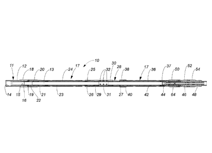
FIG. 1 is a perspective view of one embodiment of the uphole end 10 for a
compression-set straddle packer (hereinafter for the sake of simplicity,
simply
"uphole end 10") in accordance with one embodiment of the invention. The
uphole
end 10 has a multicomponent mandrel 11, the majority of which can only be seen
in a cross-sectional view (see FIGs 2a and 2b). The multicomponent mandrel 11
extends completely through the uphole end 10 and is surrounded by a
- 6 -
CA 3064207 2019-12-09
multicomponent sliding sleeve 17, which reciprocates within a limited range
over
the multicomponent mandrel 11. The multicomponent mandrel 11 includes a work
string connection component 12 with a work string connection 14 (see FIG. 2a).
A configuration of the work string connection 14 is a matter of design choice
and
dependent on whether the uphole end 10 is to be operated using a coil tubing
string (not shown) or jointed tubing string (not shown), as is well understood
in
the art.
The work string connection component 12 has a packer element compression
shoulder 15 and a packer element sleeve 16 (see FIG. 2a) that supports an
elastomeric packer element 18, the function of which is well understood in the
art.
On a downhole side of the packer element 18 is a packer element compression
ring 19 that slides on the packer element sleeve 16. A compression bell 20,
having compression bell equalization ports 21, is a component of the
multicomponent sliding sleeve 17 and is connected to an upper sliding sleeve
24.
The upper sliding sleeve 24 is connected by an upper sliding sleeve threaded
connection 25 to an upper sliding sleeve coupling 26, which is in turn
connected
to a female coupling end 27 (see FIG. 2b) of a slotted sliding sleeve 28. In
one
embodiment, the slotted sliding sleeve 28 has three slotted sliding sleeve
finger
components 29 that are respectively received in mandrel flow sub grooves 31 in
the mandrel flow sub 30. The slotted sliding sleeve finger components 29
define
three slots that respectively expose at least one mandrel flow sub nozzle of a
mandrel flow sub 30. In this embodiment, the mandrel flow sub 30 has a
plurality
of mandrel flow sub nozzles, 32. It should be understood the number of mandrel
flow sub nozzles is a matter of design choice. A downhole end of the sliding
sleeve finger components 29 are threadedly connected to a slotted sliding
sleeve
captured end coupling ring 38 that surrounds a lower sliding sleeve coupling
34
(see FIG.2a) that is threadedly connected to a lower sliding sleeve 36. A
downhole end of the lower sliding sleeve 36 is connected to a transition
sleeve
upper end 50 that is in turn connected to a transition sleeve lower end 52. A
connection joint 54, which is the final component of the multicomponent
sliding
sleeve 17, is connected to a lower end of the transition sleeve lower end 52.
The
connection joint 54 is used to connect a compression-set packer (not shown) to
- 7 -
-Substitute Page-
Date Recue/Date Received 2021-03-08
the uphole end 10 to provide a straddle packer. The compression-set packer may
be connected directly to the connection joint 54, or one or more extension
pipes
(not shown) can be connected to the connection joint 54, in which case the
compression-set packer is connected to a lower end of the extension pipe(s) to
increase a length of a well bore that is pressure isolated by the straddle
packer.
FIG. 2a is a cross-sectional view of the uphole end 10 shown in FIG. 1. As
explained above, the slotted sliding sleeve 28 is connected to the lower
sliding
sleeve 36 by the lower sliding sleeve coupling 34, which is threadedly
connected
to both the slotted sliding sleeve 28 and the lower sliding sleeve 36. The
slotted
sliding sleeve captured end coupling ring 38 that covers the lower sliding
sleeve
coupling is likewise threadedly connected to the slotted sliding sleeve 28.
Rotation of the slotted sliding sleeve captured end coupling ring 38 is
inhibited by
cap screws 40. As further explained above, the elastomeric packer element 18
is supported on the packer element sleeve 16 of the work string connection
component 12 of the multicomponent mandrel 11. The multicomponent mandrel
11 has a central passage 13 that provides an uninterrupted fluid path through
the
multicomponent mandrel 11. The multicomponent mandrel 11 includes the
following interconnected components: the work string connection component 12,
which is threadedly connected to an upper crossover tube 22 (better seen in
FIG.
2b); threadedly connected to a lower end of the upper crossover tube 22 is an
upper mandrel tube 23; the mandrel flow sub 30 connected to a downhole end of
upper mandrel tube 23; the wear-resistant, replaceable mandrel flow sub
nozzle(s) 32; a lower mandrel tube 42 connected to a downhole end of the
mandrel flow sub 30; a bias element push component 44 connected to a
.. downhole end of the lower mandrel tube 42; a bias element support component
46 having mandrel ports 64 connected to a downhole end of the bias element
push component 44; and, a mandrel termination component 48 connected to a
lower end of the bias element support component 46.
FIG. 2b is an enlarged cross-sectional view of the uphole end 10 in FIG. 2.
All of
the external and internal components of the uphole end 10 have been described
above except for one important operative component, namely a bias element 58
- 8 -
-Substitute Page-
Date Recue/Date Received 2021-03-08
housed in a bias element chamber 56 within the transition sleeve upper end 50
and the transition sleeve lower end 52 components of the multicomponent
sliding
sleeve 17. In one embodiment the bias element 58 is an elastomeric tube
carried
on the bias element support component 46. In one embodiment the tubular bias
element 58 is cast from a hydrogenated nitrile butadiene rubber (HNBR) having
a durometer of at least 90. An upper bias element push ring 60 abuts an upper
end of the bias element 58. A lower bias element push ring 62 abuts a lower
end
of the bias element 58. Both the upper bias element push ring 60 and the lower
bias element push ring 62 float on the bias element support component 46. The
bias element 58 constantly resists any movement of the upper bias element push
ring 60 toward the lower bias element push ring 62, and vice versa, thus
resisting
any relative movement of the multicomponent sliding sleeve 17 over the
multicomponent mandrel 11. As will be explained below with reference to FIG.
3,
the bias element 58 serves several important functions in the operation of the
uphole end 10.
FIG. 3 is a cross-sectional view of the uphole end 10 showing the uphole end
10
as it would appear if it was connected to a compression-set packer to provide
a
straddle packer and the straddle packer were in a packer-set condition. In the
set
condition the bias element 58 is compressed by work string weight applied from
the surface in a manner well understood in the art. When work string weight is
applied to the work string connection component 12, The multicomponent
mandrel 11 is forced downhole and slides downward within the multicomponent
sliding sleeve 17. This urges the bias element push component 44 and the upper
bias element push ring 60 to compress the bias element 58 as the bias element
support component 46 is forced downhole through the lower bias element push
ring 62. The compressed bias element 58 urges the multicomponent sliding
sleeve 17 downhole as the uphole end 10 is forced downhole to set the
compression-set packer (not shown) in a manner well known in the art.
Meanwhile, movement of the multicomponent mandrel 11 urges the packer
element compression shoulder 15 against the packer element 18 to set the
packer element 18. In addition, as the bias element 58 compresses under the
work string weight load it increases in diameter to fill the bias element
chamber
- 9 -
CA 3064207 2019-12-09
56 (see FIG. 2b) sealing mandrel ports 64 in the bias element support
component
46 and transition sleeve ports 66 in the transition sleeve upper end 50 to
prevent
any escape of high-pressure fluid pumped into the uphole end 10 through the
mandrel ports 64. However, if a screen-out (well understood in the art)
occurs,
relieving work string weight at the surface lets the bias element 58 relax as
shown
in FIG. 2b, opening the mandrel ports 64 and providing a fluid path around
opposed ends of the relaxed bias element 58 and out through the transition
sleeve ports 66 to permit high-pressure fluid trapped in the uphole end 10 to
drain
into an annulus of the well bore. The bias element 58 also assists the return
of
the uphole end 10 to the run-in position after string weight is removed from
the
work string, and prevents premature setting of the packer element 18 in the
event
a minor obstruction is tagged in the well bore while the straddle packer is
being
run into the well bore.
FIG. 4 is a perspective view of one embodiment of a bias element 58 of the
uphole
end 10 in accordance with the invention. In this embodiment, the bias element
58
has a bias element uphole end 68 and a bias element downhole end 70. However,
the bias element 58 is symmetrical and may be inserted with either end uphole.
A wide external bias element outer vent groove 74 and a corresponding bias
element inner vent groove 76 (see FIG. 5) ensure that the mandrel ports 64 and
the transition sleeve ports 66 remain open when the bias element 58 is in a
relaxed condition. A bias element central passage 72 is sized to accept the
bias
element support component 46 of the multicomponent mandrel 11. FIG. 5 is a
side elevational view of the bias element 58 shown in FIG. 4.
FIG. 6 is a perspective view another embodiment of an uphole end 10a for a
compression-set straddle packer in accordance with the invention. This
embodiment of the uphole end 10a has all of the components and features of the
uphole end described above with reference to FIGs. 1-5 with an exception that
the ports in the transition sleeve upper end 50 are elongated slots 78 to
encourage fluid egress in an event that a screen out occurs when fluid heavily
laden with proppant is being pumped through the uphole end 10a. FIG. 7 is a
cross-sectional view the embodiment of the uphole end 10a shown in FIG. 6.
- 10 -
-Substitute Page-
Date Recue/Date Received 2021-03-08
FIG. 8 is a cross-sectional view a further embodiment of an uphole end 10b for
a
compression-set straddle packer in accordance with the invention. All of the
components and features of the uphole end 10b have been described above with
reference to FIGs. 1-5 except that the bias element in the uphole end 10b is a
bias element compression spring 80. The uphole end 10b also has only the upper
bias element push ring 60, and the bias element support component 46 has no
ports. Furthermore, there are no ports in the transition sleeve upper end 50.
In
one embodiment of the uphole end 10b, the bias element compression spring 80
is preloaded with about 2,000 pounds of compression when the uphole end 10b
is assembled, and maintains that tension in an unset condition of the uphole
end
10b. The uphole end 10b is operated in the same manner as described above
with reference to the uphole end 10.
The explicit embodiments of the invention described above have been presented
by way of example only. The scope of the invention is therefore intended to be
limited solely by the scope of the appended claims.
- 11 -
-Substitute Page-
Date Recue/Date Received 2021-03-08