Note: Descriptions are shown in the official language in which they were submitted.
CA 03064300 2019-11-19
WO 2019/164731
PCT/US2019/017914
Title of Invention:
Method for Making Mg Brass EDM Wire
Technical Field:
The inventions described herein are in the field of wire manufacture.
Background Art:
It has been discovered that additions of magnesium (Mg) to brass provide an
alloy
that gives improved performance when formed into a wire for electric discharge
machining
(EDM). The brass may have zinc (Zn) concentrations in the range of 5 wt% to 50
wt%.
Suitable magnesium additions may be in the range of 0.02 wt% to 5 wt%. The
balance of
the alloy is copper (Cu) and inevitable impurities. The concentration of
copper in the
balance may be in the range of 45 wt% to 95 wt%. We refer to alloys with
compositions in
this range as "magnesium brass" or "Mg brass".
It is difficult to make Mg brass EDM wire using conventional continuous
casting
systems and methods designed to produce pure brass EDM wire. The Mg tends to
separate
out from the alloy when it is melted. Deposits tend to form on casting dies.
The wire itself
tends to be more difficult to coil and draw into a fine wire suitable for EDM.
EDM wires
typically have a diameter in the range of 0.1 mm to 0.3 mm. Larger and smaller
diameters
may be suitable for different applications. Hence there is a need for an
improved system
and method for producing Mg brass EDM wires.
Summary of Invention:
The summary of the invention is a guide to understanding the invention. It
does not
necessarily describe the most generic embodiment.
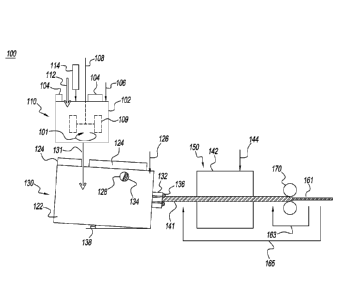
Figure 1 is a schematic of an improved system 100 for producing Mg brass EDM
wires. The system comprises:
a) a melting furnace 110 comprising:
i. a heated body 102;
1
CA 03064300 2019-11-19
WO 2019/164731
PCT/US2019/017914
ii. a cover 104;
iii. a source 106 of an inert gas adapted to purge said melting furnace of
air; and
iv. a mixer 108;
b) a holding furnace 130 comprising:
i. a body 122;
ii. a cover 124;
iii. a source 126 of an inert gas adapted to purge said holding furnace of
air; and
iv. a casting die 132;
c) an annealing furnace 150 comprising:
i. a heated body 142; and
ii. a source 144 of an inert gas adapted to purge said annealing furnace
of air; and
d) one or more drawing dies 170
wherein said system is adapted to make a Mg brass EDM wire by the steps
comprising:
e) add a bulk charge 112 of copper and zinc to said melting furnace;
f) add an additive charge 114 of magnesium to said melting furnace;
g) heat said bulk charge and said additive charge until they form a melt of Mg
brass;
h) stir 101 said melt with said mixer;
i) tap 131 said melting furnace to transfer said melt of Mg brass to said
holding
furnace;
2
CA 03064300 2019-11-19
WO 2019/164731
PCT/US2019/017914
j) cast said melt of Mg brass through said casting die to form a solid rod 141
of
said Mg brass;
k) anneal said rod in said annealing furnace; and
I) draw said annealed rod through said one or more drawing dies
to form said
Mg brass EDM wire 161.
Brief Description of Drawings:
Figure 1 is a schematic of an improved system and method for producing Mg
brass
EDM wire.
Figure 2 is a schematic of a system and method for removing deposits
comprising Mg
from a casting die and recycling said deposits into a subsequent melt of Mg
brass.
Best Mode for Carrying Out the Invention:
The detailed description describes non-limiting exemplary embodiments. Any
individual features may be combined with other features as required by
different
applications for at least the benefits described herein. As used herein, the
term "about"
means plus or minus 10% of a given value unless specifically indicated
otherwise. As used
herein, the term "substantially" means at least 90% of a desired value unless
specifically
indicated otherwise.
A portion of the disclosure of this patent document contains material to which
a
claim for copyright is made. The copyright owner has no objection to the
facsimile
reproduction by anyone of the patent document or the patent disclosure, as it
appears in
the Patent and Trademark Office patent file or records, but reserves all other
copyright
rights whatsoever.
As used herein, the term "shaped" means that an item has the overall
appearance of
a given shape even if there are minor variations from the pure form of said
given shape.
As used herein, the term "generally" when referring to a shape means that an
ordinary observer will perceive that an object has said shape even if there
are minor
variations from said shape.
3
CA 03064300 2019-11-19
WO 2019/164731
PCT/US2019/017914
As used herein, relative orientation terms, such as "up", "down", "top",
"bottom",
"left", "right", "vertical", "horizontal", "distal" and "proximal" are defined
with respect to an
initial presentation of an object and will continue to refer to the same
portion of an object
even if the object is subsequently presented with an alternative orientation,
unless
otherwise noted.
Referring again to figure 1, the bulk charge 112 may comprise a mixture of
copper
and zinc with 5 wt% to 50 wt% of the total charge being zinc. The total charge
is the bulk
charge plus the additive charge. Alternatively, the zinc may be in the range
of 30 wt% to 40
wt% of the total charge. Alternatively, the zinc may be about 35 wt% of the
total charge.
The additive charge may comprise a charge of magnesium in a container of
copper
or brass. The charge of magnesium may be in the range of 0.02 wt% to 5 wt% of
the total
charge. The charge of magnesium may be in the range of 0.05 wt% to 0.5 wt% of
the total
charge. The charge of magnesium may be about 0.1 wt% of the total charge. The
bulk
charge may be added to the melting furnace first and then melted. The additive
charge may
be added after the bulk charge has melted.
The mixer may stir the melt after the additive charge is added to the melted
bulk
charge to reduce the separation of the Mg from the melt. Mixing may be done by
any
means such as a paddle mixer 109 illustrated in figure 1. Mixing may be done
alternatively
or in combination with any mechanical mixer, any gas mixer (e.g. a bubbler),
or any
induction mixer (e.g. inductive coupling between the melt and an induction
coil in proximity
to or integral to the melting furnace).
The cover 104 may be placed on the melting furnace and the space below the
cover of
the melting furnace may be purged with an inert gas. As used herein, an "inert
gas" is any
gas mixture with an oxygen concentration less than that of air. For example, a
mixture of
nitrogen with 1 vol% oxygen produced by a membrane nitrogen generator is
considered
inert. An inert gas may comprise reducing gases such as hydrogen or carbon
monoxide.
After the additive and bulk charge have been melted, the melting furnace may
be
tapped 131 and the melt transferred to the holding furnace 130. The holding
furnace may
comprise a body 122 which may be heated. The holding furnace may further
comprise a
4
CA 03064300 2019-11-19
WO 2019/164731
PCT/US2019/017914
cover 124 and a source 126 of an inert gas. The inert gas for the holding
furnace may or
may not be the same composition as the inert gas for the melting furnace. For
example, the
inert gas for the melting furnace may be argon and the inert gas for the
holding furnace may
be nitrogen.
The holding furnace may further comprise one or more vents 128 and a casting
die
132. The holding furnace may further comprise a tilt mechanism 138 so that the
holding
furnace may be tilted as it empties to provide a constant head pressure at the
casting die.
As the holding furnace empties, a new bulk and additive charge may be added to
the
melting furnace and melted to produce a new melt. Before the holding furnace
is emptied,
the new melt may be transferred to said holding furnace to keep the casting
process
running continuously. The tilt mechanism may adjust so that the head pressure
at the
casting die is constant.
After the rod 141 is cast, it may be fed directly into an in-line annealing
furnace. The
annealing furnace may be purged with an inert gas. The inert gas for the
annealing furnace
may be different than the inert gasses for either the melting furnace or
holding furnace.
The inert gas for the annealing furnace, for example, may comprise nitrogen
and about 1
vol% hydrogen.
Alternatively, the rod may be coiled after it is cast. The coiled rod may then
be fed
into a batch annealing furnace, such as a bell furnace. Coiling the rod allows
it to be stored
so that it can be drawn down to a wire at a later time.
After the rod is annealed, it may be passed through one or more drawing dies
170 to
form a quantity of Mg brass EDM wire 161. The system may comprise a plurality
of drawing
dies with progressively smaller diameters. The step of drawing said annealed
rod may
comprise the steps of re-drawing 163 said rod through each of said plurality
of drawing dies.
The step of drawing said annealed rod may further comprise the step of re-
annealing 165
said rod after it has been drawn through one or more of said plurality of
drawing dies. For
example, the rod may be re-annealed after being drawn through three drawing
dies. The
re-annealing may be done in a different annealing furnace (not shown) than the
annealing
furnace 150 that was initially used to anneal the cast rod 141. The different
annealing
5
CA 03064300 2019-11-19
WO 2019/164731
PCT/US2019/017914
furnace may be a batch furnace (e.g. a bell furnace) or an inline furnace
(e.g. a double open-
ended furnace).
Once the Mg brass wire has reached its desired final diameter, it may be
coiled and
shipped.
Flushing Deposits from Holding Furnace
It has been found by experiment that when Mg brass is cast from a holding
furnace,
deposits 134, 136 may be formed around the vents and casting die respectively.
The
deposits may comprise magnesium.
Figure 2 is a schematic of a system and method 200 for removing the Mg
deposits
and recycling them for a future Mg brass melt. It has been surprisingly found
that the
deposits can be removed by the steps of:
a) after a melt of Mg brass has been cast into a rod, add a second bulk charge
212 of flushing metal to the melting furnace 110, said flushing metal being
operable to dissolve the deposits that may have formed on the casting die
and/or vent;
b) heat said second bulk charge to form a melt of flushing metal;
c) transfer 231 said melt of flushing metal to said holding furnace 130; and
d) cast a rod 241 of flushing metal from said flushing melt through said
casting
die 132 such that said deposits that may have formed on said casting die
and/or said vent are removed 234, 236 and dissolved in said flushing melt.
Said rod of flushing metal may be formed into a coil 204.
The flushing metal may be brass substantially comprising copper and zinc at
about
the desired concentrations in said Mg brass wire. The coil may then be
returned 202 to said
melting furnace and melted for a second melt of Mg brass. The composition of
said flushing
metal may be measured and additional Mg added to the melt to achieve a desired
concentration of Mg. The second melt of Mg brass may then be transferred to
the holding
6
CA 03064300 2019-11-19
WO 2019/164731
PCT/US2019/017914
furnace and cast into a second rod of Mg brass. The second rod of Mg brass may
then be
drawn through one or more drawing dies to form a second quantity of Mg brass
EDM wire.
In an alternative embodiment, pure copper is used as the flushing metal. When
the
flushing rod is recycled to the melting furnace, both zinc and Mg may be added
to make a
second melt of Mg brass.
In another alternative embodiment, the flushing melt can comprise any metal
that
will dissolve Mg deposits.
Casting Die
The casting die may be made from graphite or any other suitable material. It
has
been found by experiment that a graphite die suitable for casting a brass rod
may wear out
quickly when used to cast Mg brass. It has been surprisingly found that when
the graphite
die is coated, that the die life is substantially increased. Suitable coatings
include phenolic
resin and phosphorus.
Coated Wires
Mg brass EDM wires may be subsequently coated. Suitable coatings are copper,
zinc, and alloys thereof. If the Mg brass EDM wires are coated with Zn, they
may be
subsequently annealed to form gamma or epsilon brass coatings. Both coated and
uncoated wires are suitable for use in EDM machines with feedback control on
the cutting
speed that increases the speed until wire breakage. The EDM machine then sets
the cutting
speed to a slightly lower value. The wires are also suitable for use in EDM
machines with
auto-threading. It has been found by experiment that Mg brass wires auto-
thread more
reliably than conventional brass wires.
Example 1:
A charge of brass was melted in a melting furnace. The copper content was
about
64.5 wt%. This was about the desired copper concentration of 65 wt%. The
balance of the
melt was zinc and inevitable impurities. Hence the zinc content was about 35.5
wt%. This
was about the desired zinc concentration of 35 wt%. Mg was added to the heat
to bring the
7
CA 03064300 2019-11-19
WO 2019/164731
PCT/US2019/017914
Mg content to about 0.1 wt%. This was about the desired Mg concentration of
0.1 wt%.
This made a first melt of Mg brass. The first melt was transferred to a
holding furnace and
cast into a first rod of Mg brass. The first rod of Mg brass was annealed and
drawn down to
make a first quantity of Mg brass EDM wire with a diameter of about 0.25 mm.
After the first melt of Mg brass was cast, deposits were observed on the
holding
furnace vents and casting die. A charge of flushing metal was added to the
melting furnace
and melted to form a melt of flushing metal. The flushing metal had about the
same copper
and zinc content as the first melt of Mg brass. The flushing melt was
transferred to the
holding furnace and a flushing rod was cast. The deposits on both the vent and
the casting
die were dissolved in the flushing melt.
A user placed the first quantity of Mg brass EDM wire in an EDM cutting
machine
with auto-treading. Relative to regular brass wire, the Mg brass EDM wire cut
20% faster,
had fewer breaks and had consistent and reliable auto-threading. While not
wanting to be
held to the explanation, the better auto-threading may be related to having
the zinc
concentration at a level of about 35 wt%. This is close to the upper limit for
having a pure
alpha phase brass in an Mg free brass alloy. When Mg is added, this may cause
property
changes that make the wire stiffer and provide more consistent auto-treading.
It was also observed that the metal part that was cut in the EDM cutting
machine
had a smoother finish than when the same metal was cut with brass EDM wire
with no
added magnesium. It was also observed that fewer deposits were formed within
the water
bath of the EDM machine relative to regular brass EDM wire.
Example 2:
Continuing with Example 1, after the flushing rod was cast, the flushing rod
was
transferred back to the melting furnace and melted. The Mg content was
measured and
enough Mg was added to bring the Mg content to about the desired concentration
of 0.1
wt% to make a second melt of Mg brass. The second melt was then transferred to
the
holding furnace and cast into a second rod of Mg brass. The rod was then
annealed and
drawn through one or more drawing dies to form a second quantity of Mg brass
EDM wire.
8
CA 03064300 2019-11-19
WO 2019/164731
PCT/US2019/017914
The diameter of the Mg brass EDM wire was about 0.25 mm. This was in the
desired range
of 0.1 to 0.3 mm.
A user placed the second quantity of Mg brass EDM wire in an EDM cutting
machine
with auto-threading. Relative to regular brass wire, the second quantity of Mg
brass EDM
wire cut 20% faster, had fewer breaks and had consistent and reliable auto-
threading. It
was also observed that the article that was cut in the EDM cutting machine had
a smoother
finish than when the same article was cut with brass EDM wire with no added
magnesium.
It was also observed that fewer deposits were formed within the water bath of
the EDM
machine relative to regular brass EDM wire.
9
CA 03064300 2019-11-19
WO 2019/164731
PCT/US2019/017914
Conclusion
While the disclosure has been described with reference to one or more
different
exemplary embodiments, it will be understood by those skilled in the art that
various
changes may be made and equivalents may be substituted for elements thereof
without
departing from the scope of the disclosure. In addition, many modifications
may be made
to adapt to a particular situation without departing from the essential scope
or teachings
thereof. For example, a rod of Mg brass may be cast vertically instead of
horizontally.
Therefore, it is intended that the disclosure not be limited to the particular
embodiment
disclosed as the best mode contemplated for carrying out this invention.