Note: Descriptions are shown in the official language in which they were submitted.
Electrochemical Device for Cascading Reactive Distillation
RELATED APPLICATIONS
This application claims priority to US provisional application no. 62/526,873
filed on June
29, 2017.
TECHNICAL FIELD
Embodiments of the present invention relate to a reconfigurable process and
apparatus
for integrating waste conversion and material recovery within major industrial
sectors
such as electricity production, resource extraction, and waste management.
More
specifically, plasma reactors and molten salt electrochemical cells are
utilized for high-
throughput reactive distillation and chemical vapor transport of mixed solids
via
carbochlorination.
BACKGROUND
Rapid growth and modernization are the hallmarks of a healthy and vibrant
economy and
are understandably sought-after goals of nearly every nation on the planet.
The advances
in technologies developed throughout the industrial revolution and beyond have
allowed
growth by developing countries at rates and scales never previously seen.
These are
widely accepted as positive advances ideally capable of spreading to all
peoples and
bringing a better quality of life to everyone on the planet. However, the
shortcomings of
common methods and modes of resource extraction and utilization present in
modern
industry are becoming increasingly problematic. Conservative estimates put the
total
amount of waste generated globally at over 10 billion tons per year, with that
number
expected to double over the next 10 years. From an ecological, industrial, or
any realistic
viewpoint, this is not a sustainable model.
Negative effects of anthropogenic metabolism are a multi-pronged and
increasingly
apparent issue in both industrialized and developing nations around the world.
It is
becoming more widely accepted that current industrial processes cannot scale
to the
point of being accessible to more than a fraction of the world's population
without exacting
1
Date Recue/Date Received 2020-08-25
CA 03064627 2019-11-21
WO 2019/005510 PCT/1JS2018/037931
enormous tolls in terms of environmental degradation and resource
availability, offsetting
or even counteracting the sought-after gains promised by modern technologies.
Rapidly
developing countries provide an excellent case-study in how modern industrial
technologies can be leveraged to raise the standard of living in previously
unimaginably
short periods of time. These technologies, however, are not without their
drawbacks. Air
pollution and smog alerts in China's major population centers are one example,
among
many, of the consequences of scaling legacy processes along with their
associated
pollution and waste management challenges. Although alternatives have been
developed, many major industrial processes have not evolved significantly
beyond their
initial implementation. This creates an increasing environmental footprint and
gives little
thought to industrial ecology. For truly sustainable and environmentally sound
processes,
industrial symbiosis becomes essential. Further compounding the challenge,
significant
economic advantage is a prerequisite in displacing well-known processing
techniques in
what is generally a very capital intensive and risk-averse industry.
SUMMARY
Embodiments of the present invention utilize waste by way of proven industrial
methods
for highly selective electrochemical processing and molten salt gasification
with high atom
efficiency via carbochlorination looping. Various analyses of gasification
processes have
shown that a variety of feedstocks from coal, shale, bitumen, biomass, and
even garbage
can be used to produce synthetic crude and liquid fuels. However, most of
these
techniques produce significant amounts of carbon dioxide due to their reliance
on direct
oxidation. Mitigating carbon dioxide production through carbon capture and
storage tends
to rely on either cryogenic separation or electrolysis to produce pure oxygen,
both
methods having associated capital costs and energy penalties. The proposed
process
integration alleviates these disadvantages by eliminating much of the
ancillary equipment
typically used in gasification such as air separation and gas cleanup, these
features
instead being directly integrated with the syngas production. Further economic
gains are
realized through expanding available feedstocks to include various industrial
and
municipal wastes as well as the advantageous recovery and reuse of inorganic
residue
fractions. Through the chlorination of gasification residues, a three-pronged,
flexible
method of reducing carbon emission is realized. Principally, minimal oxygen is
introduced
to the process; furthermore, produced or delivered carbon dioxide may be
utilized in the
2
CA 03064627 2019-11-21
WO 2019/005510 PCMJS2018/037931
synthesis gas processing; and finally, a portion of the formed metal chlorides
may be
utilized for capturing carbon dioxide long-term as carbonate minerals.
Embodiments of the invention utilize processes having inherent carbon capture
and
conversion capabilities. Design goals are to maximize flexibility, efficiency,
and
economics while enabling environmentally and sustainably sound practices. A
hybrid
thermochemical cycle integrates pyrolysis, staged reforming and residue
chlorination.
Hydrogen generated is used to upgrade practically any carbon feedstock
including
bitumen, shale, coal, and biomass. The residues of the upgrading are
chlorinated, metals
of interest are recovered, and the remainder can be reacted to form carbonate
minerals
and construction materials. This combination provides a highly efficient
method of
producing any range of hydrocarbons, as well as various valuable metals and
materials.
The processing compliments some of the best available electricity generation
technologies such as Integrated Gasification Combined Cycle (IGCC) or
Integrated
Gasification Fuel Cell (IGFC) power plants, while enhancing efficiency and
economics by
incorporating the recovery of strategic resources and useful construction
materials.
Synthesis gas produced can be cleanly burned on-site and most carbonaceous
materials,
when utilized in the process, will produce excess power which may be sold to
the grid.
Furthermore, renewable energy sources such as solar and wind or nuclear power
can be
easily integrated for carbon neutral or negative processing (i.e. carbon
dioxide recycling)
via liquid hydrocarbon synthesis. Feedstocks, including waste of literally any
form, are
neutralized and converted to valuable commodities and/or construction
materials.
Beyond the numerous economic and environmental benefits of recovering both
energy
and metals from what are generally regarded as waste streams, embodiments of
the
invention also directly address one of the major issues with adding renewable
energy
sources to the power grid. The challenge presented by solar, wind, and
distributed
generation in general is that they are, by their very nature, variable sources
requiring
energy storage for effective integration. Electricity producers currently
require idle
generation capacity capable of meeting roughly twice the average electrical
demand. This
idle capacity is used in meeting peak conditions and reserve margins; adding
highly
variable distributed generation only compounds the challenge. A utility scale
implementation of the present invention exploits idle generator capacity as
spinning
reserve in the production of synthetic hydrocarbons. Molten salts, aside from
catalyzing
reactions, have proven useful as both thermal and electrochemical storage
solutions.
3
CA 03064627 2019-11-21
WO 2019/005510 PCT/1JS2018/037931
Thus, embodiments of the present invention present a highly adaptable platform
for
meeting the challenge of grid scale energy storage. This disclosure also
details the
technology's use in power plant retrofits, renewable energy integration, CO2
recycling,
and load following through thermal and chemical energy storage.
Through largely cyclical processing, a pathway for green chemistry and carbon
dioxide
emission reductions across a multitude of industrial processes becomes
feasible. The
unit integration itself need not follow the proposed layout and can be
economically
deployed across a broad range of scales, from multi-megawatt power plants to
tens of
kilowatts for distributed or off-grid applications.
The processing methodology deviates from traditional gasification processes in
numerous aspects. First and foremost, reforming is paired with
pyrometallurgical
techniques, taking advantage of synergies unrealized by independent processing
infrastructures. Carbo-chlorination of inorganic ash, formed by pyrolysis and
reforming,
concentrates trace elements such as precious metals and rare earth elements,
by orders
of magnitude, enabling their subsequent recovery. The bulk of the inorganic
fraction,
typically being mostly silica, is converted to gaseous chlorides such as
silicon
tetrachloride and subsequently reacted with water to form hydrogen chloride
gas as well
as nano-structured fumed silica. This form of silica, among a wide array of
other uses, is
beneficial in manufacturing ultra-high-performance cement and concretes. The
silica can
be removed through simple cyclones or filters and remaining gas and particles
are
recycled back into the gasification process. Such a process arrangement
drastically
changes the economics of power plants through the incorporation of tipping
fees for waste
disposal, cogeneration of liquid hydrocarbons, and recovery of high value
metals and
materials. Maximum value is realized from coal and various wastes through the
recovery
of trace elements as part of the energy extraction. Flexibility in carbon
sourcing also
allows for utilization of advantageous feedstocks from locally available
sources.
Carbonaceous materials can be selected from the cheapest available
hydrocarbons or
even waste materials such as electronics waste, which can have precious metal
content
exceeding a kilogram per tonne (1000 ppm).
A particularly significant aspect of the design utilizes chemical looping
which, provided a
proper energy source, can reform carbon dioxide through synthesis gas
processing.
4
CA 03064627 2019-11-21
WO 2019/005510 PCT/1JS2018/037931
Modular reactors are ideal because they can be installed in banks and added as
required
for scaling or integrating process add-ons. In practice, virtually any energy
source may
be incorporated to reduce direct oxidation (via air), which in turn reduces
the amount of
carbon dioxide either captured or rejected to the environment.
Embodiments of the invention expand gasification technologies to incorporate
chlorination. This strategy expands the potential feedstock to virtually any
materials that
can be beneficially broken down for the recovery of valuable constituent
elements.
Carbon dioxide still forms through the reduction or carbochlorination of
various metals,
however portions of these metal chlorides, such as calcium chloride, may
subsequently
be utilized in capturing carbon dioxide as carbonate minerals. Furthermore,
electrolysis
may be incorporated to advantageously remove oxygen from multiple processing
steps.
For instance, a reversible fuel cell stack can be used for peak electricity
generation and
reversed to produce extra syngas for hydrocarbon production when electricity
demand is
low.
Further advantages are made apparent when considering the combined
functionality of
the individual units' operations. Utilization of plasma reactors allows for
very compact
processing equipment. In turn, this extreme process intensification lends
itself to modular
design and economies of scale in the production of individual processing
units. The three
main unit operations presented can scale dramatically depending on the
feedstock's
content of water, carbon, ash, etc. To compensate for this, in a full-scale
operation, the
core operations are designed as modules which dynamically adjust their feed
and product
composition, forming a cascading series with higher capacity operations
utilizing multiple
parallel units. This scaling compounds the advantage of high processing
intensity and
can be expanded upon through multiple redundant processing trains.
Utilizing the present invention's core processing, an assortment of
traditional metallurgy
and hydrocarbon processing unit operations can be integrated. This disclosure
focuses
on advanced technologies that compliment an all-of-the-above energy strategy.
Renewable and nuclear energy sources can be used to power liquid hydrocarbon
synthesis, storing energy in a practical and familiar medium with a vast
infrastructure
already in place for its transportation and beneficial use. Pyrolysis and
gasification of
biomass along with more typical feedstock is a proven and scalable method of
producing
carbon-neutral biofuels and petrochemicals. Metallurgical processing
byproducts can
CA 03064627 2019-11-21
WO 2019/005510 PCMJS2018/037931
provide useful heat and materials to the core molten salt reactors. Recovery
of precious
metals and rare-earths are of significant interest and related processing
could be tightly
integrated. For instance, lead bullion may be processed to recover gold,
silver, and
PGMs, while the produced dross is reprocessed for heat and material recovery.
Higher
temperature operations such as iron and steel production can also be
integrated as a
high-quality heat source, recovering useful heat from the off-gas and slag
produced.
Access to appropriate heat (500C+) is required for high reforming throughput.
This heat
is produced via the core electrochemical and plasma reactions and distributed
to
subsystems that require heat for reaction (endothermic). The ideal power
source for
enabling full functionality would be an Advanced High Temperature Nuclear
Reactor. In
addition to providing baseload electricity, heat could be utilized directly
without the
inefficiency of first converting it to electricity. Several Generation IV
reactors are suitable
for this purpose and modular designs allow for scalable operations as well as
the potential
for integrating carbon dioxide recycling at a future date. Along with storing
energy via
hydrocarbon synthesis, various thermal and chemical energy storage options are
available. The molten salt itself, acting as a thermal reservoir, compensates
for variability
in feedstock and operating conditions. This could be easily extended by
increasing the
volume of molten salt or adding dedicated reservoirs for the sole purpose of
thermal
storage. Various reactive compounds created via carbochlorination can also be
utilized
as an energy storage medium. Finally, the electrochemical cells forming the
core
processing share commonalities with molten metal/salt batteries and may have
use as
such. A plurality of operational modes could be utilized for efficiently
converting and
storing energy.
BRIEF DESCRIPTION OF DRAWINGS
FIG. 1 illustrates a highly compact implementation of the present invention.
Subsystems
referenced in the figure are briefly described as follows:
1.01 (Stage 1 or Si) Plasma pyrolysis and reforming of incoming solids
1.02 (Stage 2 or S2) Electrochemically assisted carbochlorination of oxides
1.03 (Stage 3 or S3) Molten salt reforming and synthesis gas cleaning
1.04 Plasma reactor (electro-burner) for processing chloride gas
1.05 Cyclone separation of produced nano-solids
6
CA 03064627 2019-11-21
WO 2019/005510 PCMJS2018/037931
1.06 Chemical vapor transport of rare earth chlorides
1.07 Electrolysis of molten salt for metal recovery and chlorine gas
production
1.08 Processing of lead bullion for high-value metal recovery
1.09 Lead bullion including precious metal content
1.10 Molten chloride salt product of S2 (1.02)
1.11 Produced clean syngas or hydrogen
1.12 Off-gas from Si to S3 (via 1.13)
1.13 Off-gas from Si to S3 (via 1.12)
1.14 Off-gas from S2 to Si (via 1.15)
1.15 Off-gas from S2 to S1 (via 1.14)
1.16 Produced raw synthesis gas from Si (1.01)
1.17 Produced raw chloride gas from S2 (1.02)
1.18 Produced cleaned syngas from S3 (1.03)
1.19 Chlorine gas to S2 (1.02)
1.20 Partially chlorinated molten salt and ash from Si (1.01)
1.21 Molten salts (OH, CO3) from S3 (1.03)
1.22 Sodium salts to S3 (1.03)
1.23 Make-up salts to S3 (1.03)
1.24 Make-up chlorine to S2 (1.02)
1.25 Ore feed
1.26 Water feed
1.27 Solid carbonaceous feed
1.28 Steam and light hydrocarbon gas feed
1.29 Electrolytically produced metals (e.g. Magnesium)
1.30 Rare earth concentrate
1.31 Non-ferrous metal recovery (e.g. PGMs)
1.32 Nano-structured solid oxides (e.g. fumed silica)
1.33 Bulk solids removal (e.g. calcium sulfate, sulfide, carbonate, etc.)
Subsystems 1.01, 1.02, and 1.03 will henceforth be referred to by their
arbitrary stage
designations Si, S2, and S3.
FIG. 2 illustrates a hypothetical hybrid "X to liquids" integration.
Subsystems referenced
in the figure are briefly described as follows:
7
CA 03064627 2019-11-21
WO 2019/005510 PCMJS2018/037931
2.01 Molten salt trapping of entrained carbon
2.02 Volatilization of carbonaceous feedstock
2.03 Distillation of raw hydrocarbon gas stream (bulk or fractional)
2.04 Fischer-Tropsch (FT) reactor
2.05 Heat exchanger (HX) integrated with FT reactor (2.04)
2.06 Electric motor/generator mechanically connected to 2.07 and 2.08
2.07 Hydrocarbon gas compressor
2.08 Hydrocarbon gas expander
2.09 Off-gas from Si (equivalent to 1.16)
2.10 Molten salt and entrained carbon to S1
2.11 Molten salt from S3
2.12 Molten salt and carbon to S3
2.13 Near-coke to S1
2.14 Light hydrocarbon gas to compression (2.07)
2.15 Synthesis gas from power island (equivalent to 3.14)
2.16 Light hydrocarbon gas to S3 (equivalent to 1.12)
2.17 Condensed water to FT-HX (2.05)
2.18 Cooling water input
2.19 Carbon dioxide input (pressurized) to FT-HX (2.05)
2.20 Natural gas input (pressurized) to FT-HX (2.05)
2.21 Syncrude product output
2.22 Raw hydrocarbon gas
2.23 Synthesis gas
FIG. 3 illustrates a hypothetical high-efficiency power cycle with carbon
capture.
Subsystems referenced in the figure are briefly described as follows:
3.01 Molten carbonate electrodialysis stack
3.02 Solid oxide fuel cell stack
3.03 Working fluid recuperator (heat exchanger)
3.04 Water condenser (heat exchanger)
3.05 Cooler for product carbon dioxide stream (heat exchanger)
3.06 Molten salt heat transfer (heat exchanger) from S3
3.07 Liquid chemical looping combustion integrated with S3
3.08 Air recuperator (heat exchanger)
8
CA 03064627 2019-11-21
WO 2019/005510 PCT/1JS2018/037931
3.09 Electric motor/generator mechanically connected to 3.10 -3.12
3.10 Working fluid expander
3.11 Working fluid compressor
3.12 Fuel gas compressor
3.13 Syngas from S3 (equivalent to 1.11)
3.14 Syngas (hydrogen-rich) to FT (2.04)
3.15 Syngas (oxygen-rich) fuel
3.16 Ambient air
3.17 Working fluid (super-critical carbon dioxide)
3.18 Pressurized carbon dioxide product
3.19 Condensed water product
FIG. 4 illustrates a simplified cross-sectional view of several possible
embodiments of an
electrochemically assisted molten salt carbochlorination apparatus.
Arrangements
depicted in the illustration are as follows:
4.1 A solid carbon electrode in direct contact with the molten salt.
4.2 A hollow solid carbon electrode wherein feedstock is injected directly
into
and forced to pass through the plasma created via electric arcing.
4.3 A solid carbon electrode located coaxially within a non-conducting
electrode
sheath.
4.4 Molten-metal electrode
4.5 Solid carbon electrode
4.6 Fused (molten) salt electrolyte
4.7 Electrode channel
4.8 Reactor headspace
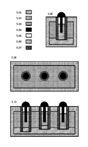
FIG. 5 illustrates one possible embodiment of the electrochemical reactor
assemblies.
5.01 Molten-metal electrode
5.02 Fused salt electrolyte of internal reactor
5.03 Fused salt (containment salt) of external enclosure
5.04 Electrode assembly
5.05 Reactor headspace
5.06 External enclosure
9
CA 03064627 2019-11-21
WO 2019/005510 PCMJS2018/037931
5.07 Internal reactor (cell) containment wall
5.08 Cross-sectional view of the narrow end of the device
5.09 Cross-sectional view of the device from the top down
5.10 Cross-sectional view of the broad side of the device
DETAILED DESCRIPTION
With reference to FIG. 1, the three reaction stages are Stage 1 (Si) - Plasma
Pyrolysis /
Plasma Reforming (1.01), Stage 2 (S2) - Submerged Arc Molten Salt Chlorination
(1.02),
and Stage 3 (S3) - Molten Salt Reforming (1.03). There are two distinct
material flows,
which are contacted within the reactors for various energy and material
exchanges:
gaseous products (1.16, 1.17, 1.18) flow countercurrent to the solid/liquid
product (1.09,
1.10, 1.20, 1.21). An explanation of each core process and various sub-
processes, with
alternative arrangements, and chemistry involved will highlight the benefits
of this process
engineering as well as the chemistries employed in the tight coupling of the
reactors. One
feature of the design emerges from the countercurrent flows, as well as
various feedback
loops. This looping, coupled with variable feedstocks (1.23, 1.24, 1.25, 1.26,
1.27, 1.28)
introduces a level of hysteresis not commonly found in continuous industrial
processing.
Flexibility of the individual reaction stages operating as a complex adaptive
system
compensates for this, as will become apparent in the following description.
Stage 3 (S3) is the final processing step of the product synthesis gas (1.11)
and operates
as a reformer as well as providing deep gas cleaning. A bed of molten sodium
salts
(hydroxide and carbonates) (1.22) reacts with water and hydrocarbons (1.28)
fed to the
reactor to produce hydrogen and carbon oxides (1.18). Operation at high
pressures
enables cost effective integration with Fischer Tropsch units (2.04), high
efficiency fuel
cells (3.02), or carbon dioxide separation (3.18). The resulting hydrogen
(1.18) can be
utilized by various petrochemical and/or electricity production units (3.13).
The operation
is capable of processing solid, liquid, or gaseous forms of hydrocarbons
without
modification, as well as contaminated or "produced water" from the oil
industry. The
molten salts utilized break down feed material, wherein liberated sulfur,
halogens and
inorganics present are retained within the salt. Product gas composition is
determined by
feedstock and the energy requirements vary in direct relation. As part of the
proposed
integration, only gaseous feedstocks (including entrained carbon), along with
water,
makeup salts (1.23), and potentially salts produced by chlorination (1.10)
would enter the
CA 03064627 2019-11-21
WO 2019/005510 PCMJS2018/037931
reactor. If alkaline recycling is employed, chlorides coming from the
chlorination (S2)
would make up only a small fraction of the total salt, so that chlorine is not
allowed to
saturate the reactor (S3) and migrate to the product gas stream (1.11). Solids
produced
primarily through calcium salt reactions can be removed by filtering (1.33)
and liquids are
sent to Si.
Stage 1 (Si) is responsible for breaking down solid feed (1.27). It can be
operated in
various modes determined by feedstock as well as electrical input. When a high
ratio of
oxygen to carbon is available, through introducing water or carbon dioxide for
instance, a
reforming mode is realized. Reforming water and/or carbon dioxide in this way
is very
energy intensive however. A more efficient operating mode is obtained in an
oxygen
starved environment such as the plasma pyrolysis of pulverized coal and/or
natural gas.
In such an oxygen-deficient environment, hydrogen and carbon oxides are
produced, and
a stoichiometric excess of carbon may form carbon black particles, which
become
entrained within the gas stream (1.16). This carbon can be effectively
stripped from the
gas by molten salts (2.01), or simply carried by the gas to cleaning (S3). The
inorganic
ash formed by plasma pyrolysis (51) becomes heated to the point of
vitrification and
collects in the bottom of the reactor. This ash also reacts with incoming
carbon dioxide
and hydrogen chloride products (1.14 = 1.15) from the plasma reaction (1.04)
of steam
and chlorinated gases (1.17) produced through chlorination (S2), causing mild
residue
chlorination within the pyrolysis stage (Si). Here, a careful balance of
incoming alkaline
content (1.27) should be maintained to limit the amount of chlorine passing
through Si
and on to S3 (1.12 = 1.13)
Stage 2 (S2) is where carbochlorination is elegantly slipstreamed into the
staged
reforming. Here, partially chlorinated residue from Si is fully chlorinated.
By full
chlorination, it is meant that sufficient carbon (1.25, 1.20) and chlorine
(1.19) are
introduced to effectively convert all remaining compounds into chlorides.
Closed,
submerged electric arc furnaces are used within a biphasic molten salt system,
being
effectively agnostic to feed composition. This produces a byproduct non-
volatile molten
salt (1.10) concentrated with rare earth chlorides (1.30), which are
subsequently
separated (1.06). A volatile chloride gas stream (1.17) forms the primary
product; this
chloride gas comprising halogenated silicon, aluminum, iron, titanium,
vanadium, etc.
Stage 2 (S2) separates the bulk volatilized material (1.17) from non-volatile
Group 1 and
2 metals, lanthanides, and actinides, as well as scandium and yttrium; all of
which remain
11
CA 03064627 2019-11-21
WO 2019/005510 PCT/1JS2018/037931
in the molten chloride melt (1.10). Taking place in a molten salt (wet)
process minimizes
requirements for gaseous chlorine used in more familiar (dry) chlorination
processes. A
consumable electrode (4.5) comprising carbon and/or mixed oxides produces an
electric
arc with an associated molten metal electrode (4.4) present at the base of the
reactor.
Lead makes for an ideal counter-electrode due to its low melting point and
ability to act
as a solvent for various other metals including copper, precious metals (PM),
and
platinum group metals (PGM). The molten metal collector (4.4), while acting as
a cathode,
concentrates low reactivity metals from the molten salt (4.6). Reverse
polarity (anodic)
reactions of the bipolar electrode (4.4) drive more reactive components to
degrade the
molten salt (4.6). Levels of carbon and other reactive components are
especially
important regarding anodic activity of the bipolar electrode (4.4). For
various reasons, an
AC or any alternative waveform arc may be employed. Volatilization of elements
within a
specified electronegativity range are determined through voltage and/or
oxidizer
(chlorine) availability. For simplicity, it should be assumed that an
abundance of carbon
present forms a baseline reductive environment. Electrochemical processing
thus
provides activation energy for the carbochlorination, carbon carries oxygen
away, and
silicon and other elements form volatile chlorides (1.17) transported with the
carbon
dioxide. The molten metal (4.4) and molten salt (4.6) form immiscible phases
within the
reactor, which can then be independently tapped as valuable concentrates
(1.09, 1.10).
This results in raised reaction kinetics, enabled via electrochemical
activation and mixing.
FIG. 1 also utilizes a plasma electro-burner (1.04) for reacting steam (1.26)
with the
produced gaseous chlorides (1.17). In typical titanium production, the
volatile gases are
separated by condensing them to their liquid states. The same could be
practiced in this
processing as well, however, it would add to the overall capital cost and
footprint of the
equipment. An electro-burner (1.04) is presented in the example as a direct
route to
removing (1.05) unwanted elements (1.32) from the variable composition gas
stream
(1.17) in a highly controllable manner. If desired, magnetic separation of
iron oxide
produced in the reaction could also be utilized due to the very fine particle
sizes.
Processing conditions should be matched to the intended feedstocks as well as
economic
constraints. In most situations, a difficult to produce high purity fumed
silica has little to
no advantage over a much simpler mixed oxide nano-powder (1.32) for use in
high
performance construction materials.
12
CA 03064627 2019-11-21
WO 2019/005510 PCMJS2018/037931
Lead bullion (1.09), forming the electrode (4.4) of the staged processing (Si,
S2, S3) can
be directly utilized in a typical non-ferrous refinery (1.08). Alternatively,
various methods
could be integrated onsite to recover and refine the most valuable of the
metals (1.31).
Returning the lead to the core stages in a molten, non-molten, oxidized (Pb0,
PbCl2,
PbS, etc.) or metallic state can provide numerous processing efficiencies.
Once again,
there are situational trade-offs to be determined. Lead processing and recycle
through
simple integration may make sense depending on scale.
The molten chloride salt concentrate (1.10) produced by S2 has a wide variety
of options
available for recovering rare earth elements (REE) as well as some of the more
valuable
alkali and alkaline earth metals. Chemical vapor transport (CVT) of the REEs
is a well-
studied phenomenon and an environmentally-friendly alternative to typical
methods of
REE extraction. In CVT, rare earth chlorides are complexed with aluminum
chloride
vapors and transported as a gas (1.06). They then deposit as solids (1.30) at
a lower
temperature, or could alternatively be stripped by ionic liquids. Besides CVT,
the molten
salt also lends itself to high temperature electrolytic processing (1.07) for
removing metals
such as magnesium (1.29). The byproduct of the molten salt electrolysis is
chlorine gas
(1.19), which may be recycled to the chlorination process, lowering demand for
make-up
chlorine (1.24). Processing the salt concentrate is not limited to
pyrometallurgy; a vast
range of hydrometallurgical methods are known and practiced on a large scale
such as
chlor-alkali, ammonia-soda, and other variant processes. Whatever methods are
utilized,
post-processing, some portion of the salts (1.22) may also be returned to S3,
reducing
the need for make-up salts (1.23). For small installations, the produced REE-
laden molten
salt may simply be sold to an off-site refiner.
With reference to FIG. 2, an advanced hybrid "X to Liquids" liquefaction
operation is
illustrated, capable of extracting useful hydrocarbons from literally any
carbon-based
feedstock (2.02), including low-grade fuels, biomass, and waste. The hybrid
liquefaction
combines indirect synthesis-gas based Fischer-Tropsch processing (2.04) with
direct
liquefaction (2.02) to produce a raw syncrude (2.22) that may undergo
fractional
distillation (2.03) or be sent to a refinery as high-grade crude oil (2.21).
Syngas from S3 (1.11 = 3.13) is processed via electrodialysis (3.01) to an
ideal H2:CO
ratio (3.14) and is routed (3.14 = 2.15) to the F-T reactor (2.04). The F-T
reactor heat
exchanger (2.05) transfers heat from the incoming gas stream as well as heat
produced
13
CA 03064627 2019-11-21
WO 2019/005510 PCMJS2018/037931
by the exothermic hydrocarbon synthesis (2.04), producing high-grade steam for
S2 (2.16
= 1.12). Compressed or liquefied natural gas (2.20) as well as carbon dioxide
(2.19) can
be injected along with cooling water (2.17). The combined gases move heat from
F-T
(2.04) to S3, as well as creating an ideal stoichiometric composition for
reforming (S3).
Volatile hydrocarbons produced through F-T are expanded (2.08), combined with
incoming gases (2.22) from feedstock volatilization (2.02), and condensed
(2.03) to
syncrude (2.21) or various hydrocarbon fractions. Non-condensed gases (2.14)
are then
combined with a portion of cleaned syngas (2.23) from Si (2.09 = 1.13),
compressed
(2.07), merged with steam and other light gases from FT-HX (2.05), and routed
to S3
(2.16 = 1.12). That concludes the indirect processing portion of hydrocarbon
synthesis.
Simultaneous to the F-T processing (2.04), direct liquefaction (2.01) of
incoming solid
feedstock is driven by the low-pressure S1 off-gas (2.09 = 1.13). Light gases
from S1
containing entrained carbon particles (2.09) are stripped of carbon (2.01) by
contact with
molten salts (2.11) from S3. The carbon-laden salt can then be routed to
either S1 or S2,
to meet carbon requirements (2.10), or returned (2.12) to S3. A portion of the
cleaned
syngas (2.23) is pressurized (2.07) and sent to S3 (2.16 = 1.12), while the
remainder is
used to liquefy and/or pyrolyze solid feedstock (2.02). The solid residue
and/or spent
catalyst (2.13) then goes to Si. Volatilized hydrocarbons (2.22) are distilled
(2.03) and
the non-condensed gases (2.14) proceed to S3.
The combination of direct and indirect liquefaction utilizes benefits of each
technology,
enabling more efficient conversion than either is capable of alone, while
sharing common
equipment capital and operational expenses. This hybrid approach enables
carbon-
neutral fuels, virtually limitless energy storage, and carbon dioxide
recycling.
With reference to FIG. 3, a variety of power cycle options are available for
converting the
produced synthesis gas (1.11 = 3.13) into electricity; internal combustion,
steam boiler,
gas turbine, and fuel cells represent a few compatible technologies.
Illustrated are several
unique options for carbon dioxide reduction the present invention enables,
which are
advantageous when compared with typical power cycles.
Synthesis gas coming from S3 (1.11 = 3.13) is thoroughly cleaned of any
compounds that
might foul electrochemical cells, which the illustration advantageously
utilizes. First, the
gas stream is split and directed through the anode and cathode of a molten
carbonate
electrodialysis stack (3.01). This transfers oxygen from the cathode stream
(3.14) and
concentrates it in the anode stream (3.15). The oxygen-deficient (hydrogen-
enriched)
14
CA 03064627 2019-11-21
WO 2019/005510 PCMJS2018/037931
stream (3.14) is utilized in liquid hydrocarbon processing (3.14 = 2.15).
Oxygen
deficiency, in this case, meaning a higher (H2+CO) / (H20+002) ratio than the
oxygen
rich stream. The oxygen-rich stream (3.15) feeds to a modified Allam-type
thermodynamic
cycle. The Allam power cycle is a good starting point for integrating
electricity production
for various reasons. The major advantages of this cycle are high power density
and
integrated carbon capture using supercritical 002 for the working fluid.
A "typical" Allam cycle operates roughly as follows:
1) high-temperature, supercritical CO2 is expanded through a turbine
(producing
mechanical work that drives a generator, producing electricity)
2) sc-002 is cooled and water is condensed out
3) sc-002 is compressed to high pressure and an amount equivalent to that
produced by
the burned fuel is separated
4) fuel is added to the gas stream, corn busted, and the cycle repeats
The variation outlined in this disclosure uses a hybrid Allam cycle. The
hybrid cycle
eliminates requirements for cryogenic air separation, removing direct
combustion entirely,
while retaining the advantages of integrated carbon capture and a relatively
simple cycle.
A high-temperature fuel cell (3.02) operating from 500-900C is utilized as the
topping
cycle. The cell stack (3.02) runs incoming synthesis gas (3.13, 3.15) through
the anode
side and heated air through the cathode. This prevents dilution of the CO2
working fluid
(3.17) by atmospheric nitrogen and an economizer (3.08) transfers heat from
the exhaust
stream to the incoming air (3.16). The exhausted (oxidized) fuel is mixed with
the bulk
working fluid (3.17) and run through the typical Allam-cycle steps: expanded
(3.10),
cooled (3.03), water condensed (3.04), re-compressed (3.11), excess carbon
dioxide
removed (3.05), and reheated (3.03). In place of direct combustion, a second
heat
exchanger (3.06) is also utilized in reheating the working fluid. This
secondary heat
exchanger (3.06) draws from S3 and there is no mixing of the power-cycles'
working fluid
with reactants from that process. A chemical looping reaction (3.07) is shown
to
accommodate the added heat-load, molten metals (4.4) react with oxygen from
air (3.16),
then get reduced in S3 (reacting exothermically with carbon) and the process
is repeated.
In the diagram, the air intake/exhaust for the high-temperature fuel cell
(3.02) and the
molten-metal-oxide chemical-looping (3.07) utilize a common economizer (3.08).
CA 03064627 2019-11-21
WO 2019/005510 PCT/1JS2018/037931
The described power cycle integration allows for high-efficiency, integrated
CO2 capture
(3.18), water conservation (3.19), and electricity generation (3.09).
FIG. 4 illustrates a simplified cross-sectional view of several possible
embodiments of an
electrochemically assisted molten salt carbochlorination apparatus. These
drawings will
look familiar to those of ordinary skill in the art of electric arc furnace
operation with a few
notable exceptions. Common electric arc furnaces have a molten iron charge,
which is
lead in this case. Hence, the reactor can be operated at much lower
temperatures than
typical electric arc furnaces due to lead's much lower melting point.
Likewise, rather than
a layer of slag, a layer of fused salt is utilized. Furthermore, operating
with a fused salt
requires a different set of design criteria regarding corrosion, redox,
electrochemical
operations, etc. than would be typical in electric arc furnace operation.
4.1 depicts a simple implementation wherein the solid carbon electrode is in
direct contact
with the molten salt, the salt being ionically conductive and possibly having
a wide range
of electrical conductivity, depending on composition. This implementation may
forgo
arcing and rather act as an electrolytic cell or resistive heater. If the
electrode is raised, it
may arc to the fused salt (depending on conductivity and/or voltage).
Feedstock would
enter directly into the headspace.
4.2 depicts a hollow solid carbon electrode wherein feedstock is injected
directly into and
forced to pass through the plasma created via electric arcing. Depending on
the
composition of the fused salt, it may be desirable to have the electrode
raised out of the
molten salt or submerged within it. The conductivity of the salt and operating
voltage will
determine any plasma forming phenomena.
4.3 depicts a solid carbon electrode located coaxially within a non-conducting
electrode
sheath, thus forming an annulus for the injection of reactants. In this
embodiment, the
feedstock is forced not only through the electric arc plasma but must also
pass through
the molten salt before off-gas escapes to the headspace. In this
configuration, the arc's
ability to operate in a submerged mode is decoupled from the electrical
conductivity of
the fused salt. This results from the non-conducting sheath, being submerged,
encasing
the electrode and preventing electrode contact with the salt.
16
CA 03064627 2019-11-21
WO 2019/005510 PCT/1JS2018/037931
The three examples depicted are in no way a limiting set of possible electrode
configurations. They are presented as several options available for
utilization within the
electrode assemblies (5.04) of the instant invention.
With reference to FIG. 5, a specific embodiment of the electrochemical
apparatus central
to the instant invention is illustrated. This drawing is an extension of FIG.4
such that the
electrode arrangements depicted therein are used by individual reactors within
a more
complex electrochemical device depicted herein. For simplicity, assume the
electrode
arrangement of FIG. 4.3 is utilized, along with a hollow carbon electrode and
various other
feeder, gas handling, electrode handling, power and control systems, forming a
single
assembly, herein referred to as "electrode assembly" (5.04). Furthermore, the
device
comprises multiple electrochemical reactors (cells), each comprising a unique
electrode
assembly, internal containment structure, headspace, and molten salt
component. The
multiple electrochemical reactors comprising the device share common
components such
as the molten-metal electrode, a secondary salt or containment salt, external
enclosure,
power supply, etc.
Illustration 5.10 depicts components used in the electrochemical operation of
the device.
For simplicity, the electrode assembly (5.04), wherever referenced, further
comprises
power supply, feed handling, and control systems. The outer containment (5.06)
can be
of any shape and size. Here, that containment is presented as a rectangular
box meant
to resemble a multimodal shipping container. The outer containment has less
stringent
corrosion concerns than the internal containment (5.07), with the outer (5.6)
being in
contact with a lower temperature (roughly 600 +/-100 C) hydroxide and
carbonate salt,
as well as molten lead. As such, it can be made of simple steel (possibly a
high-nickel
alloy with anti-corrosion coating). If the device were operated within
something like a
multimodal container, it would be prudent to have a thermal and electrically
insulating
material between the outer containment wall and the multimodal container. The
outer
containment (5.06), containment salt (5.03), and molten metal (5.01) together
represent
S3 of the instant invention. Although it is feasible to integrate S3 directly
with the device
as shown, it would likely be beneficial for thermal storage, modularity,
scaling, and various
other reasons to move the actual reactions of S3 to a large specialized
pressure vessel
and circulate the molten metal and/or salt between the outer containment
(5.06) and said
specialized pressure vessel. At the top of the containment (5.06), where the
external
containment meets the internal reactor walls (5.07), a hermetic seal is
assumed for gas
17
CA 03064627 2019-11-21
WO 2019/005510 PCMJS2018/037931
handling. Thus, the entire control apparatus can be removed or replaced for
individual
internal reactors via the electrode assemblies (5.04).
Each internal electrochemical reactor (cell) is separated from the containment
environment via a wall of suitable refractory material (5.07). FIG. 5 shows
these as
cylinders, but they may be of any appropriate shape. Depending on the desired
electrochemical functionality, the refractory material may be non-conducting
such as
quartz or SiAION (silicon-alum inum-oxynitride) or conducting such as
graphite. The
internal separator (5.07), being in intimate proximity with corrosive
materials and
reactions of the internal reactors, is intended to be a serviceable part like
the electrode
assembly. By controlling the temperature and composition of the molten salts,
a solid
passivation layer (skull) may be formed to limit corrosion of the internal
separator.
Through an arrangement of gas handling and real-time monitoring of the
processing,
these cells form S1 and S2 of the instant invention. Three are shown in the
picture (5.10),
operating via 3-phase power, and having a dedicated reactor for Si and S2 as
well as an
intermediate stage. Integrating more reactors enables, larger, high-throughput
systems
with redundancy via cascading dynamic reactive distillation. This cascade may
be entirely
serial (adhering to the described stages), have one or more cells operating in
parallel,
combine serial and parallel cells and dynamically adjust for the reaction's
progression
from Si to S2 (level of chlorination), or incorporate other stages for
specific material
recovery (e.g. CVT of REE). Thus, a counter-current cascade is developed
wherein gases
flow from one reactor to the next, while solid/liquid material shifts from
stage to stage. If
designed appropriately, the overall electrochemical device could theoretically
operate as
a secondary cell, rectifier, or other functions beneficial to grid operations.
The electrochemical processing being undertaken should be understood as
electrochemical activation of various redox reaction mechanisms of the desired
carbochlorination and pyrolysis reactions. Stated another way, the device
electrochemically assists carbochlorination and reforming. This means imposed
voltage
between the electrodes orchestrates non-spontaneous (thermodynamically
unfavorable)
reactions, (i.e. electro-deoxidation of silica, etc.), triggering a
physicochemical cascade,
enhancing the desired reaction kinetics. Basic electrochemical phenomena
(electrochemical activation) common to many processes such as electro-
extraction and
electro-refining drive the process. In this case, the desired products are
primarily
gaseous, meaning rather than depositing material, products are removed through
chemical vapor transport according to Le Chatelier's principle. The
electrochemical
18
CA 03064627 2019-11-21
WO 2019/005510 PCMJS2018/037931
processing thus fluxes the reactor, producing a range of activated complexes
too broad
to feasibly consider. The net result is electro-catalysis-like behavior,
except in this case
the electrodes actively take part in the reactions, degrading and converting
the electrolyte.
Hence, renewal and replacement of the electrode components are addressed in
the
design of the present invention. The device depicted in 5.10 shows three of
the cells
(electrochemical reactors) with each having various salt levels. Each cell may
have a
different level of salt, and may furthermore be operated at varying pressures.
Many more
operating conditions may be altered, with the unifying feature being their
shared
components, both within the enclosure and without (i.e. control and power
supply
systems).
The progression of the cells from Si to S2 then is an arbitrary division of
stages based
on the overall chlorination of the charge (molten salt, dissolved and
unreacted feed). Si
is assumed to "start" with a salt similar in composition to S3. As feed
enters, it undergoes
flash pyrolysis, if not already pyrolytic. As chlorine containing compounds
enter, the salt
becomes progressively chlorinated. As oxides enter, they will accumulate if a
suitable
carbochlorination rate is lacking, eventually leading to an overfill or worse
(freezing) of
the cell. One method of addressing an overfill would be to pressurize the
cell, purging
some or all its salt (5.02) to the containment salt (5.03), then introducing
fresh salt from
S3. However, it would be preferable to avoid purging by having a suitable
processing train
which ramps up chlorination gradually. To avoid freezing and to adjust to the
variable
composition of the charge, each cell can independently vary its internal
resistance (i.e.
heat generation) through raising and lowering the solid electrode (5.04).
Electricity
converted to heat in this way benefits S3 vis-a-vis the containment salt
continually
drawing heat from the cells.
The actual embodiment of the invention may vary considerably from the
illustrated
embodiments without extending beyond the scope of this disclosure, and any
limitations
should be drawn exclusively through the appended claims, with any reference to
an
element in the singular signifying "one or more" unless specifically stated
otherwise.
19