Note: Descriptions are shown in the official language in which they were submitted.
SYSTEM AND METHOD FOR SELECTING FLUID
SYSTEMS FOR HYDRAULIC FRACTURING
TECHNICAL FIELD
[0001] This application is directed, in general, to subterranean
formation fracturing and,
more specifically, to a method of workflow processing for fracturing a
hydrocarbon wellbore
formation and a wellbore fracturing system for a subterranean formation.
BACKGROUND
[0002] Hydraulic fracturing or "fracking" is a type of subsurface well
stimulation,
whereby formation fluid removal is enhanced by increasing well productivity.
The process of
fracking, also known as induced hydraulic fracturing, involves mixing a
formation proppant
(e.g., sand) and chemicals in water to form a formation fracturing fluid
(i.e., a fracturing fluid)
and injecting the fracturing fluid at a high pressure through a wellbore into
a subterranean
formation. Small fractures are formed, allowing formation fluids (e.g.,
formation gas, petroleum,
and brine water), to migrate into the wellbore for harvesting. Once the
hydraulic pressure is
reduced back to equilibrium, the sand or other formation proppant particles
hold the fractures
open.
[0003] Multi-stage hydraulic fracturing is an advancement that provides
harvesting of
fluids along a single wellbore or fracturing string. The fracturing string,
usually for vertical or
horizontal wellbores, passes through different geological zones. Some
geological zones do not
require harvesting, since desired natural resources are not located in those
zones. These zones
can be isolated so that no fracking action occurs in these zones that are
empty of desired natural
resources. Other zones having natural resources employ portions of the
fracturing string to
harvest these productive zones.
¨1¨
CA 3065051 2019-12-13
[0004]
Instead of having to alternate between drilling deeper and fracturing
operations, a
system of fracking sleeves and packers can be installed within a wellbore to
form the fracturing
string in a multi-stage fracturing process. The sleeves and packers are
positioned within zones of
the wellbore. Fracking can be performed in stages by selectively activating
sleeves and packers,
thereby isolating particular subterranean zones. Each target zone can then be
fracked stage by
stage, for example, by sealing off selected zones, and perforating or
fracturing without
interruptions due to having to drill between each fracturing stage.
SUMMARY
[0005]
The disclosure provides a workflow for fracturing a subterranean formation. In
one example, the workflow includes: (1) qualifying equipment, logistic and
environmental
wellsite conditions and constraints for fracturing the subterranean formation,
(2) determining
functional aspects of one or more fracturing fluid systems to meet the
equipment, logistic or
environmental conditions and constraints for fracturing the subterranean
formation based on
fracturing databases or models, and (3) recommending at least one of the one
or more fracturing
fluid systems for use in fracturing the subterranean formation.
[0006]
The disclosure also provides a workflow controller for fracturing a
subterranean
formation. In one example, the workflow controller includes: (1) a fracturing
fluid delivery unit
configured to apply a fracturing fluid system recommendation to the
subterranean formation, and
(2) a workflow processing unit configured to determine functional aspects of
one or more
fracturing fluid systems from fracturing models or databases to provide the
fracturing fluid
system recommendation for the subterranean formation.
[0007]
The disclosure further provides a hydrocarbon wellbore fracturing system for a
subterranean formation. In one example, the hydrocarbon wellbore fracturing
system includes:
-2 -
CA 3065051 2019-12-13
(1) wellbore fracturing resources coupled through a wellbore conveyance to the
subterranean
formation. (2) a fracturing fluid delivery unit that applies a fracturing
fluid system
recommendation to the subterranean formation, and (3) a workflow processing
unit that
determines functional aspects of one or more fracturing fluid systems from
fracturing models or
databases to provide the fracturing fluid system recommendation for the
subterranean formation.
BRIEF DESCRIPTION
[0008] Reference is now made to the following descriptions taken in
conjunction with the
accompanying drawings, in which:
[0009] FIG. 1 illustrates a hydrocarbon wellbore fracturing system
constructed according
to the principles of this disclosure;
[0010] FIG. 2 illustrates an example of a pre-job planning workflow
carried out
according to principles of the present disclosure;
[0011] FIG. 3 illustrates an example of a real-time operating workflow
carried out
according to principles of the present disclosure;
[0012] FIG. 4 illustrates an example of a workflow for generating a pre-
job fracturing
fluid system library carried out according to the principles of the
disclosure;
[0013] FIG. 5 illustrates an example of a workflow for generating a real-
time fracturing
fluid system library carried out according to the principles of the
disclosure, and
[0014] FIG. 6 illustrates an example of a workflow for fracturing a
subterranean
formation carried out according to the principles of the disclosure.
DETAILED DESCRIPTION
[0015] This disclosure provides fracturing workflows that allow selection
and
recommendation of one or more fracturing fluid systems for a wellbore. These
selections and
¨3 -
CA 3065051 2019-12-13
recommendations address both pre-job planning and real-time operating
conditions and employ a
relative treating pressure model and a proppant transport efficiency model
that provide field-
scalable laboratory data. Friction reducers, particularly viscosifying
friction reducers, have
competing performance requirements. In general, proppant transport capability
has to be
sacrificed in order to maximize friction reduction and pump wear and tear, for
example. An
optimal balance is dependent on a friction reducer selection as well as
individual wellbore
application conditions and requirements. For example, an optimal fluid system
can change
dramatically depending on water quality available for a fracturing job.
Additionally,
differentiation in the friction reducer market has become more difficult to
achieve as it has
become increasingly commoditized where numerous friction reduction products
are marketed
without clear performance distinctions.
[0016]
The disclosure provides examples of fracturing workflows that address
selection
of a more appropriate fluid system recommendation for application to varying
wellbore
conditions, as well as, provide a more comprehensive relative performance
analysis in a variety
of application conditions. Additionally, design recommendations may be
addressed when
moving to a new fluid system and real-time fluid system selection or
optimization
recommendations for changing application conditions or requirements may be
addressed. These
may include competing fluid system performance factors such as transport
efficiency, friction
reduction or equipment maintenance, for a wide array of application conditions
such as water
quality, wellbore geometry, fracturing fleet makeup and pumping schedule.
These may be
subject to a variety of customizable performance goals such as minimization of
fracture treating
pressure, maintenance issues, pumping times, fuel consumption or total cost of
ownership (TCO)
issues while maximizing proppant concentration and slurry rate.
-4-
CA 3065051 2019-12-13
[0017] For purposes of this disclosure, the term "workflow" is defined as
an orchestrated
and repeatable pattern of activity that is enabled by a systematic
organization of resources to
process information, transform materials or provide services. Additionally,
pre-job planning for
fracturing of a subterranean formation is defined as determining one or more
fracturing fluid
systems that may be applied through a wellbore to provide fracturing of a
subterranean formation
before an actual fracturing operation begins. Correspondingly, real-time
operating for fracturing
of a subterranean formation is defined as actually applying a selected or
recommended fracturing
fluid system through a wellbore to provide fracturing of the subterranean
formation. And, a
proppant distribution index (PDI) is defined as a general index for how well a
particular
fracturing fluid system conveys proppant for a particular set of wellbore or
environmental
conditions. Also, the PDI is a means of quantifying the ability of a
fracturing fluid system to
convey proppant under the particular set of conditions.
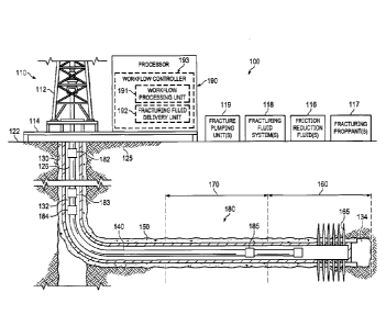
[0018] FIG. 1 illustrates a hydrocarbon wellbore fracturing system for a
subterranean
formation, generally designated 100, constructed according to the principles
of this disclosure.
The system 100 provides an example of an operating environment to discuss
certain aspects of
this disclosure. As depicted, the system 100 may suitably include a drilling
rig 110 positioned
on the earth's surface 122 and extending over and around a wellbore 130
penetrating a
subterranean formation 125 for the purpose of primarily recovering
hydrocarbons. The wellbore
130 may be drilled into the subterranean formation 125 using any suitable
drilling technique. In
one example, the drilling rig 110 includes a derrick 112 with a rig floor 114.
The drilling rig 110
may be conventional and may include a motor driven winch or other associated
equipment for
extending a work string, or a casing string into the wellbore 130. The
components of the system
100 can be coupled together via conventional connections.
-5-
CA 3065051 2019-12-13
[0019] In one example, the wellbore 130 may extend substantially
vertically away from
the earth's surface 122 over a vertical wellbore portion 132, or may deviate
at any angle from the
earth's surface 120 over a deviated or horizontal wellbore portion 134. The
wellbore 130 may
include one or more deviated or horizontal wellbore portions 134. In
alternative operating
environments, portions or substantially all of the wellbore 130 may be
vertical, deviated,
horizontal or curved. The horizontal, vertical, curved, or deviated nature of
any wellbore is not
to be construed as limiting the disclosure to any particular wellbore
configuration. The wellbore
130 includes a casing string 140. In the example of FIG. 1, the casing string
140 is secured into
position in the subterranean formation 125 in a conventional manner using
cement 150.
(0020] In accordance with the disclosure, the system 100 includes one or
more fracturing
zones. While only two fracturing zones (e.g., a lower fracturing zone 160 and
upper fracturing
zone 170) are illustrated in FIG. 1, and it is further illustrated that the
two fracturing zones are
located in a horizontal section 134 of the wellbore 130, it should be
understood that the number
of fracturing zones for a given well system 100 is almost limitless, and the
location of the
fracturing zones is not limited to horizontal portions 134 of the wellbore
130. In the embodiment
of FIG. 1, the lower fracturing zone 160 has already been fractured, as
illustrated by the fractures
165 therein. In contrast, the upper fracturing zone 170 has not been
fractured, but in this
example is substantially ready for perforating and/or fracturing. Fracturing
zones, such as those
in FIG. 1, may vary in depth, length (e.g., 30-150 meters in certain
situations), diameter, etc., and
remain within the scope of the disclosure.
[0021] While the system 100 depicted in FIG. 1 illustrates a stationary
drilling rig 110,
one of ordinary skill in the art will readily appreciate that mobile workover
rigs, wellbore
servicing units (e.g., coiled tubing units), and the like may be similarly
employed. Further, while
-6-
CA 3065051 2019-12-13
the system 100 depicted in FIG. 1 refers to a wellbore penetrating the earth's
surface on dry land,
it should be understood that one or more of the apparatuses, systems or
methods illustrated
herein may alternatively be employed in other operational environments, such
as within an
offshore wellbore operational environment, for example, a wellbore penetrating
a subterranean
formation beneath a body of water. Although the system 100 provides examples
of fracturing for
a single wellbore, multiple wellbores may employ fracturing operations
concurrently. These
concurrent operations may employ a common source for fracturing resources such
as friction
reducing fluids and fracturing proppants, or they may be distributed to each
wellbore or a subset
of the total number of wellbores being fractured. Also, a multiple wellbore
fracturing operation
may employ a common central processor or divide wellbore processing among
several
processors. Additionally, a fracturing water quality analysis may be performed
for a common
water supply for a multiple wellbore operation, or may be performed
individually for separate
water supplies
(0022]
The system 100 additionally includes surface equipment such as one or more
pumping units 119 and wellbore fracturing resources such as friction fluids
116, fracturing
proppants 117 and fracturing fluid systems 118 employing at least a portion of
the friction fluids
116 and fracturing proppants 117. In the illustrated example, these fracturing
fluid systems 118
are pumped, by the pumping units 119, through a wellbore conveyance 126 to the
downhole tool
assembly 180. The wellbore conveyance 126 may be a drill pipe or another type
of conveyance
sufficient to handle the pressure used for fracturing. The hydrocarbon
workflow system 100
further includes wellbore pressure determining means such as pressure gauges.
These pressure
gauges may include a wellhead pressure gauge 182 that provides a surface
wellhead pressure
-7-
CA 3065051 2019-12-13
(WHP) and a bottom hole pressure gauge 185 that provides a bottom hole gauge
pressure
(BHGP) that is communicated to the surface 122.
[ 0023 ] Additionally included is at least one wellbore pressure gauge (in
this example,
represented by WP1 183 through WPn 184 pressure gauges) that determines an
intermediate
wellbore pressure, which is communicated to the surface 122. These
intermediate wellbore
pressures may be employed to facilitate verification of a uniform fracturing
fluid condition
throughout the wellbore 130. In another example, electrical or optical sensors
(not expressly
shown) may be placed in an annular space between casing and formation where
they are
typically cemented in place. These sensors are communicatively coupled to an
electrical or
optical cable (not expressly shown) that is controlled by a processor 190 at
the surface 122. The
optical cable may include multiple optical fibers that may be used for
distributed temperature
sensing or distributed acoustic sensing.
[0024] The processor 190 includes a workflow processing unit 191 having
fracturing
models or databases to determine functional aspects of one or more fracturing
fluid systems that
provide a fracturing fluid system recommendation for the subterranean
formation; and a
fracturing fluid delivery unit 192 that applies the fracturing fluid system
recommendation to the
subterranean formation. The workflow processing unit 191 and the fracturing
fluid delivery unit
192 are included in a workflow controller 193 that is part of the processor
190, in this example.
[ 0025 ] The processor 190 calculates a wellbore friction pressure for a
selected fracturing
fluid system and manages the fracturing fluid system to maintain the wellbore
friction pressure
within predetermined limits. This wellbore friction pressure may be employed
to calibrate or
update a friction model that may be employed in fracturing the wellbore 130.
The processor 190
may employ or store executable programs of sequences of software instructions
to perform one
- 8 -
CA 3065051 2019-12-13
or more of various calculations including a wellbore friction pressure,
updating a wellbore
friction model or selecting various fracturing fluid systems, for example. The
software
instructions of such programs may represent algorithms and be encoded in
machine-executable
form on non-transitory digital data storage media, (e.g., magnetic or optical
disks, random-access
memory (RAM), magnetic hard disks, flash memories, and/or read-only memory
(ROM)), to
enable the processor 190 to perform one, multiple or all of the steps of one
or more of the
described methods, functions, systems or apparatuses described herein.
Portions of disclosed
examples may relate to computer storage products with a non-transitory
computer-readable
medium that have program code thereon for performing various computer-
implemented
operations that embody a part of an apparatus, device or carry out the steps
of a method set forth
herein.
[0026] Non-transitory used herein refers to all computer-readable media
except for
transitory, propagating signals. Examples of non-transitory computer-readable
media include,
but are not limited to: magnetic media such as hard disks, floppy disks, and
magnetic tape as
well as optical media such as CD-ROM disks; magneto-optical media in general
and hardware
devices that are specially configured to store and execute program code, such
as ROM and RAM
devices. Examples of program code include both machine code, such as that
produced by a
compiler, and files containing higher level code that may be executed by the
computer using an
interpreter.
[0027] If real-time BHGP data is available, the processor 190 can employ
the
methodology of this disclosure and can be utilized for real-time control and
optimization of a
fracturing fluid system, including selection of a friction reducer and
proppant type and
concentration. Note that the disclosed method or approach includes the use of
multiple BHGP
-9-
CA 3065051 2019-12-13
data if available, which will serve to enhance the accuracy of the real-time
calculations and
improve operational decisions.
[ 0028] The disclosed approach may also be used to vary the concentration
of friction
reducers and/or types of friction reducers as well as a concentration of
proppant over time
(before/flush, during ramp-up, during stage, during ramp-down, after/flush) to
determine fluid
friction relationships that can be used to optimize treatment pressures in
real time either during a
current fracturing stage or from stage to stage. A real-time control algorithm
may be included in
the processor 190 acting as a surface equipment control system, where various
step-up/step-
down sequences may be introduced to automatically determine and differentiate
fluid friction
and proppant friction induced pressure drop.
[ 002 9] The disclosed approach can additionally be used to also
distinguish between
friction pressures inside the wellbore and in the near-wellbore region
including formation
perforations. An example application of this disclosure may be to evaluate an
effectiveness of a
diversion treatment. All of this information may proactively be used to model
bottom-hole
treating pressure, and select combinations of friction reducers or friction
reducer concentrations
as well as a proppant concentration to reach a target bottom-hole treating
pressure in real time.
The measured data can be shared with real-time models, and the modeled data
can be used to
determine operating set-points for fracture treatments in real time.
Additionally, the pressure
response of a treatment can be measured enabling real-time fracture control
and automation.
[ 0030 ] FIG. 2 illustrates an example of a pre-job planning workflow for
fracturing a
wellbore formation, generally designated 200, carried out according to
principles of the
disclosure. The pre-job planning workflow 200 illustrates a systematic
organization of resources
that may be employed for fracturing a wellbore formation, such as that shown
in FIG. 1, as may
- 1 0 -
CA 3065051 2019-12-13
be directed by the workflow controller 193. The pre-job planning workflow 200
employs pre-
job planning fracturing models and databases 205, one or more pre-job planning
fluid system
selections 210 and one or more pre-job planning fluid system recommendations
215. In the
illustrated example, pre-job planning fracturing models and databases 205 are
included for
application-specific performance success goals that focus on certain
application areas such as
minimizing friction or equipment maintenance or maximizing proppant transport,
for example.
Basically, the performance success goals focus on what is being optimized in a
particular
fractioning operation or application. This may also include keeping a cost
factor within a
specified range or maximizing proppant transport where available water sources
are of poor
quality.
(0031] Also included in the pre-job planning workflow 200 are fracturing
models and
databases 205 for predicting successful pumping of fracturing operations that
may be difficult to
achieve from a pure physics or first principles standpoint. That is,
predetermining if pumping X
gallons of friction reducer per thousand gallons of water at Y barrels per
minute with Z pounds
of proppant per gallon is going to be accomplished successfully. Or, if
something is going to
cause a "screen-out" that basically occurs when the proppant falls out of
solution, causing
wellbore pressure to increase to a point that one can no longer pump into the
wellbore.
Therefore, models or databases for successful pumping operation predictions
may be employed
that are based on historical results. This approach may basically be a "data
bucket" approach,
but could include physics-based models also.
(0032] Additionally the pre-job planning workflow 200 fracturing models
and databases
205 for equipment maintenance calculations that are based on how many pumping
trucks, what
kind of pumping trucks and what kind of supporting equipment are being used
for fracturing the
- 11 -
CA 3065051 2019-12-13
wellbore formation. Knowing a treating pressure, a pumping rate and pumping
equipment's
rotational velocity as well as basically knowing how the pumps are going to be
employed to
complete a fracturing job enables calculation of wear and tear on the
equipment or how much
maintenance will be needed for the equipment based on the pumping conditions.
[0033] Further employed in the pre-job planning workflow 200 are
fracturing models and
databases 205 for planned application conditions that provide an overview or
summary of
wellbore conditions and fracturing water quality that are known ahead of time.
These may
include fluid performance issues that are tied to wellbore geometry and will
affect the friction
conditions or the amount of shear the fracturing fluid gets while pumping and
will need to be
addressed ahead of time. Knowing an amount and type of salts contained in the
fracturing water
that may be determined from a water analysis or relying on historical water
data for the area may
also be addressed. Still further included in the pre-job planning workflow 200
are fracturing
models and databases 205 for a fracturing fluid system library and fracturing
fluid system costs.
Generation of these two items is further addressed below.
[0034] The one or more pre-job planning fluid system selections 210
employ fracturing
fluid system selections from the fracturing fluid systems library that are
particularly suited for
use in fracturing the wellbore formation being addressed or considered. This
results in the one or
more pre-job planning fluid system recommendations 215 being recommended for
use in
fracturing the wellbore formation under consideration.
[0035] FIG. 3 illustrates an example of a real-time operating workflow
for fracturing
through a wellbore, generally designated 300, carried out according to
principles of the
disclosure. The real-time operating workflow 300 also illustrates a systematic
organization of
resources that may be employed for fracturing a wellbore formation, such as
that shown in FIG.
-12-
CA 3065051 2019-12-13
1 and are organized for real-time fracturing conditions. The workflow
controller 193 provides
control of generating real-time fracturing models and databases 305, one or
more real-time fluid
system selections 310 and one or more fluid system recommendations 315. In the
illustrated
example, the one or more fluid system recommendations 315 have real-time
optimization
capability, as well.
[0036] The real-time operating fracturing models and databases 305 employ
application-
specific performance success goals, successful pumping operation predictions
and equipment
maintenance calculations, as before. These three areas mirror those discussed
with respect to
FIG. 2. However, all of the real-time operating fracturing models and
databases 305 have to
"live on location" meaning that they are subject to being updated and modified
in real time to
accommodate changes generated by a wellbore fracturing environment currently
being addressed
and engaged in. Therefore, these three workflow areas are required to
accommodate changes
and upgrades in real time, as differentiated for their roles in pre-job
planning applications.
Additionally, the real-time operating fracturing models and databases 305
include areas for real-
time application changes and additional logical constraints. These last two
areas may have to
accommodate changes corresponding to conditions such as different water
quality availability,
higher than expected treating pressures required, being forced to switch to
different fracturing
fluids and proppants and only part of a needed 150 million gallons per month
is available, for
example.
[0037] The one or more real-time fluid system selections 310 includes
fracturing fluid
system selections from the fracturing fluid systems library that are
particularly suited for use in
fracturing the wellbore formation being addressed or considered. This results
in the one or more
¨13 -
CA 3065051 2019-12-13
pre-job planning fluid system recommendations 315 being recommended for use in
fracturing the
wellbore under consideration.
(0038] FIG. 4 illustrates an example of a workflow for generating a pre-
job fracturing
fluid system library, generally designated 400, carried out according to the
principles of the
disclosure. The workflow 400 may be carried out in the processor 190 as
directed by the
workflow controller 193 and begins with a new or existing fluid, proppant and
water
combination in a workflow stage 405. Then, in one example, the workflow 400
moves to a
friction loop testing workflow stage 410 wherein the friction loop testing
results in a laboratory
friction reduction fluid percentage (fconclab), in a workflow stage 415, that
is scaled up to field
conditions in a workflow stage 420. If a friction model exists, this scaled up
result may be
alternately employed in a workflow stage 435 to provide a "scaled-up to field
conditions"
(fconcfc) in the workflow stage 425 to become part of the fluid systems
library in the workflow
stage 430. Field systems costs in a workflow stage 440 are provided that
correspond to the field
systems library contents. Additionally, proppant transport testing may be
accomplished in a
workflow stage 445 that leads to a proppant distribution index (PDI) in a
workflow stage 450 for
inclusion in the fluid systems library.
[0039] In one example, the friction loop testing workflow stage 410 may
employ a
method of calculating a friction pressure for a wellbore wherein a uniform
fluid condition is
provided for a fracturing fluid in the wellbore. Then, time-series bottom hole
gauge pressure
data are sampled in the wellbore after the uniform fluid condition of the
fracturing fluid is
achieved. The samples of the time-series data may be processed to improve data
sample quality
wherein this processing may generally include cleaning or filtering of the
samples of the time-
series bottom hole gauge pressure data. A friction pressure is calculated for
each sample of the
¨ 1 4 -
CA 3065051 2019-12-13
time-series bottom hole gauge pressure data, and this calculated friction
pressure may be
employed for scaling laboratory data to determine friction pressure in a
hydraulic fracturing
stage. Additionally, the proppant transport testing may be accomplished for
the workflow stage
445, in one example, by employing a slot flow test wherein the proppant
distribution index (PDI)
is plotted versus a viscosity of a fracturing fluid solution.
[ 0040 ]
FIG. 5 illustrates an example of a workflow for generating a real-time
fracturing
fluid system library, generally designated 500, carried out according to the
principles of the
disclosure. The workflow 500 may be carried out in the processor 190 as
directed by the
workflow controller 193 of FIG. 1 wherein generation of a real-time fluid
systems library begins
with a determination as to if an existing fluid and proppant system exists in
a workflow stage
505. If it does exist in the workflow stage 505, it is added to the fluid
systems library in a
workflow stage 535. A fluid systems cost for this existing fluid and proppant
system is added in
a workflow stage 530. Alternately, if a real-time bottom hole gauge (BHG)
pressure in the
workflow stage 510 and a proppant distribution index (PDI) from testing or a
model are available
in the workflow stage 515, then a real-time friction reduction percentage
(FR%) in a workflow
stage 525 can be obtained resulting in an addition to the fluid systems
library in the workflow
stage 535. Again, a fluid system cost can be added in the workflow stage 530.
However, if
either of the real-time bottom hole gauge (BHG) pressure in the workflow stage
510 or the
proppant distribution index (PDI) testing or model in the workflow stage 515
are not available, a
real-time operating solution to real-time fluid systems library generation is
not available as
indicated in a workflow stage 540
[ 0041]
FIG. 6 illustrates an example of a workflow for fracturing a subterranean
formation. The workflow 600 starts in a step (or stage) 605. Equipment,
logistic and
¨15 -
CA 3065051 2019-12-13
environmental wellsite conditions and constraints for fracturing the
subterranean formation are
qualified in a step 610. Then, functional aspects of one or more fracturing
fluid systems are
determined to meet the wellsite fracturing equipment, logistic or
environmental conditions and
constraints for fracturing the subterranean formation based on fracturing
databases or models, in
a step 615. At least one of the one or more fracturing fluid systems for use
in fracturing the
subterranean formation is recommended, in a step 620. In some examples, a
processor, such as
the processor 190 of FIG, I may provide the recommendation.
One of the recommended
fracturing fluid systems for fracturing the subterranean formation is applied,
in a step 625. The
recommended fracturing fluid systems for use in fracturing the subterranean
formation are
updated, in a step 630.
(0042] In
one example, the recommended fracturing fluid system is applied in a real-
time fracturing operation. In another example, the updating is based on
changes in wellsite
fracturing equipment, logistic or environmental conditions or constraints for
fracturing the
subterranean formation. In yet another example, selection of the fracturing
databases and models
includes friction loop testing at a fracturing wellsite corresponding to the
subterranean formation.
In still another example, selection of the fracturing databases or models
includes friction loop
testing at a fracturing wellsite corresponding to the subterranean formation.
In a further
example, determining the functional aspects of one or more fracturing fluid
systems based on
fracturing databases and models includes proppant transport testing. In a
still further example,
the proppant transport testing includes determining a proppant distribution
index (PDI) by a slot
flow test, a physical model, a database model, a statistical or empirical
model, a performance
model based on a past fracturing effort, a field or laboratory rheology test
or a pipe flow test. In
a yet further example, at least a portion of the databases or models
correspond to application-
- 1 6 -
CA 3065051 2019-12-13
specific performance success goals, successful pumping operations, equipment
maintenance
calculations, planned application conditions, real-time application changes,
additional logistics
constraints, fracturing fluid system costs or a fracturing fluid systems
library. The workflow 600
ends in a step 635.
[ 0043 ] While the methods disclosed herein has been described and shown
with reference
to particular steps performed in a particular order, it will be understood
that these steps may be
combined, subdivided, or reordered to form an equivalent method without
departing from the
teachings of the present disclosure. Accordingly, unless specifically
indicated herein, the order
or the grouping of the steps is not a limitation of the present disclosure.
[ 0044 ] A portion of the above-described apparatus, systems or methods
may be
embodied in or performed by various analog or digital data processors, wherein
the processors
are programmed or store executable programs of sequences of software
instructions to perform
one or more of the steps of the methods. A processor may be, for example, a
programmable
logic device such as a programmable array logic (PAL), a generic array logic
(GAL), a field
programmable gate arrays (FPGA), or another type of computer processing device
(CPD). The
software instructions of such programs may represent algorithms and be encoded
in machine-
executable form on non-transitory digital data storage media, e.g., magnetic
or optical disks,
random-access memory (RAM), magnetic hard disks, flash memories, and/or read-
only memory
(ROM), to enable various types of digital data processors or computers to
perform one, multiple
or all of the steps of one or more of the above-described methods, or
functions, systems or
apparatuses described herein.
[ 0045] Portions of disclosed examples or embodiments may relate to
computer storage
products with a non-transitory computer-readable medium that have program code
thereon for
¨17 -
CA 3065051 2019-12-13
performing various computer-implemented operations that embody a part of an
apparatus, device
or carry out the steps of a method set forth herein. Non-transitory used
herein refers to all
computer-readable media except for transitory, propagating signals. Examples
of non-transitory
computer-readable media include, but are not limited to: magnetic media such
as hard disks,
floppy disks, and magnetic tape; optical media such as CD-ROM disks; magneto-
optical media
such as floppy disks; and hardware devices that are specially configured to
store and execute
program code, such as ROM and RAM devices. Examples of program code include
both
machine code, such as produced by a compiler, and files containing higher
level code that may
be executed by the computer using an interpreter.
[0046] Those skilled in the art to which this application relates will
appreciate that other
and further additions, deletions, substitutions and modifications may be made
to the described
embodiments.
[0047] Various aspects of the disclosure include:
[0048] In one aspect, there is provided a workflow for fracturing a
subterranean
formation including (1) qualifying equipment, logistic and environmental
wellsite conditions and
constraints for fracturing the subterranean formation, (2) determining
functional aspects of one
or more fracturing fluid systems to meet the equipment, logistic or
environmental conditions and
constraints for fracturing the subterranean formation based on fracturing
databases or models,
wherein development of the fracturing databases or models includes: friction
loop testing at or
apart from a fracturing wellsite corresponding to the subterranean formation;
and proppant
transport testing, wherein the proppant transport testing includes determining
a proppant
distribution index (PDI) by a slot flow test, a physical model, a database
model, a statistical or
empirical model, a performance model based on a past fracturing effort, a
field or laboratory
-18-
Date Recue/Date Received 2022-03-14
rheology test, or a pipe flow test (3) recommending at least one of the one or
more fracturing
fluid systems for use in fracturing the subterranean formation, and (4)
applying a recommended
one of the one or more fracturing fluid systems through a wellbore for
fracturing the
subterranean formation.
[0049]
In another aspect, there is provided a workflow controller for fracturing a
subterranean formation, including (1)
a fracturing fluid delivery unit configured to apply a fracturing fluid system
recommendation to
the subterranean formation, and (2) a workflow processing unit configured to
determine
functional aspects of one or more fracturing fluid systems from fracturing
models or databases to
provide the fracturing fluid system recommendation for the subterranean
formation, wherein the
fracturing databases or models are developed through: friction loop tests at
or apart from a
fracturing wellsite corresponding to the subterranean formation; and proppant
transport testing,
wherein the proppant transport testing includes determination of a proppant
distribution index
(PDI) by a slot flow test, a physical model, a database model, a statistical
or empirical model, a
performance model based on a past fracturing effort, a field or laboratory
rheology test or a pipe
flow test.
[0050]
In another aspect, there is provided a hydrocarbon wellbore fracturing system
for
a subterranean formation, including (1) wellbore fracturing resources coupled
through a wellbore
conveyance to the subterranean formation. (2) a fracturing fluid delivery unit
that applies a
fracturing fluid system recommendation to the subterranean formation, and (3)
a workflow
processing unit that determines functional aspects of one or more fracturing
fluid systems from
fracturing models or databases to provide the fracturing fluid system
recommendation for the
subterranean formation, wherein the fracturing models or databases are
developed through:
-19-
Date Recue/Date Received 2022-03-14
friction loop tests at or apart from a fracturing wellsite corresponding to
the subterranean
formation; and proppant transport testing, wherein the proppant transport
testing includes
determination of a proppant distribution index (PDI) by a slot flow test, a
physical model, a
database model, a statistical or empirical model, a performance model based on
a past fracturing
effort, a field or laboratory theology test or a pipe flow test.
[0051]
In some embodiments, the workflow further comprises applying a recommended
one of the fracturing fluid systems for fracturing the subterranean formation.
In some
embodiments, the recommended fracturing fluid system is applied in a real-time
fracturing
operation. In some embodiments, the workflow further comprises updating the
recommended
fracturing fluid systems for use in fracturing the subterranean formation. In
some embodiments,
the updating is based on changes in equipment, logistic or environmental
conditions or
constraints for fracturing the subterranean formation. In some embodiments,
development of the
fracturing databases or models includes measuring a bottomhole gage pressure
of the fracturing
wellsite corresponding to the subterranean formation. In some embodiments, at
least a portion of
the databases and models correspond to application-specific performance
success goals,
successful pumping operations, equipment maintenance calculations, planned
application
conditions, real-time application changes, additional logistics constraints,
fracturing fluid system
costs or a fracturing fluid systems library. In some embodiments, the
controller further
comprising a fracturing system processor that includes the workflow processing
unit or the
fracturing fluid delivery unit.
In some embodiments, the fracturing fluid system
recommendation is applied by the fracturing fluid delivery unit in a real-time
fracturing
operation. In some embodiments, the controller further comprises updating the
fracturing fluid
system recommendation during the real-time fracturing operation. In some
embodiments, the
-20-
Date Recue/Date Received 2022-03-14
updating is based on changes in equipment, logistic or environmental
conditions or constraints
for fracturing the subterranean formation. In some embodiments, the fracturing
databases or
models are developed through measurement of a bottomhole gage pressure of a
fracturing
wellsite corresponding to the subterranean formation. In some embodiments, at
least a portion of
the databases or models corresponds to application-specific performance
success goals,
successful pumping operations, equipment maintenance calculations, planned
application
conditions, real-time application changes, additional logistics constraints,
fracturing fluid system
costs or a fracturing fluid systems library.
-21-
Date Recue/Date Received 2022-03-14