Note: Descriptions are shown in the official language in which they were submitted.
CA 03065310 2019-11-27
WO 2018/222817
PCT/US2018/035309
DEVICE AND METHODS FOR PROVIDING A LOCK FOR PREVENTING
UNWANTED ACCESS TO A LOCKED ENCLOSURE
Cross-Reference to Related Applications
[0001] This application claims priority to U.S. Provisional
Application
Serial No. 62/514,135, filed on June 2, 2017 (pending), the disclosure of
which
is hereby incorporated by reference in its entirety.
Technical Field
[0001] Embodiments relate generally to locks, and more specifically,
to
high security locks implemented for use in safes and other security structures
or
areas.
Background
[0002] Items of extremely sensitive nature or very high proprietary
value
often must be stored securely in a safe or other containment device, with
access to the items restricted to selected individuals given a predetermined
combination code necessary to enable authorized unlocking thereof. It is
essential to ensure against unauthorized unlocking of such safe containers by
persons employing conventional safe-cracking techniques or sophisticated
equipment for applying electrical or magnetic fields, high mechanical forces,
or
accelerations intended to manipulate elements of the locking mechanism to
thereby open it.
[0003] Further, various applications of protecting safe containers
from
unauthorized access require that the locking mechanism satisfy a specified
physical footprint while also being more highly susceptible to observing
techniques attempting to determine the predetermined combination code as
entered by authorized individuals that have possession of the predetermined
combination code. Numerous locking mechanisms are known which employ
various combinations of mechanical, electrical and magnetic elements both to
ensure against unauthorized operation and to effect cooperative movements
among the elements for authorized locking and unlocking operations. However,
such conventional locking mechanisms employ approaches to enter the
predetermined combination code that may be easily obtained by a casual
observer. For example, a casual observer may easily determine the
predetermined combination after the authorized individual correctly enters the
-1-
CA 03065310 2019-11-27
WO 2018/222817
PCT/US2018/035309
predetermined combination code via a conventional push button and/or dial
approach.
[0004] Embodiments, as more fully disclosed hereinbelow, meets these
perceived needs at reasonable cost with a geometrically compact, electrically
autonomous, locking mechanism.
Summary
[0005] In accordance with an exemplary embodiment of the present
invention, a self-powered lock for preventing unwanted opening of a locked
enclosure is provided. The self-powered lock includes a housing and a lock
bolt
mounted for movement between a locked position and an unlocked position. A
motor is included in the housing and has a rotatable output gear. The rack
gear
engages the rotatable output gear. A pin is coupled with the rack gear. A
manually operable electricity generator generates electricity upon manual
actuation by the user. The electricity generator is electrically connected to
the
motor to supply electricity thereto for operating the rotatable output gear. A
lever arm is movable between the disengaged and engageable positions and
operatively coupled to the lock bolt to move the lock bolt between the locked
and unlocked positions. A rotary element is engageable with the lever arm in
the engageable position thereof. Rotation of the rotary element when the
rotary
element is engaged with the lever arm moves the lock bolt between the locked
and unlocked positions. The pin normally blocks the lever arm from moving
from the disengaged position to the engageable position. When the motor is
actuated by electricity from the electricity generator, the rotatable output
gear
moves the rack gear and the pin to unblock the lever arm and thereby allowing
the lever arm to engage with the rotary element to allow a user to rotate the
rotary element to move the lock bolt between the locked and unlocked
positions.
[0006] According to another exemplary embodiment of the present
invention, a self-powered lock is provided. The self-powered lock includes a
housing and a lock bolt that is movable manually between a locked position and
an unlocked position relative to the housing. A motor is included in the
housing
and has a rotatable output gear. A rack gear engages the rotatable output
gear. A manually operable electricity generator generates electricity upon
manual actuation by the user. The electricity generator is electrically
connected
-2-
CA 03065310 2019-11-27
WO 2018/222817
PCT/US2018/035309
to the motor to supply electricity thereto for operating the rotatable output
gear.
A lever arm is movable between the disengaged and engageable positions and
is operatively coupled to the lock bolt to move the lock bolt between the
locked
and unlocked positions. A rotary element is engageable with the lever arm in
the engageable position thereof. The rotation of the rotary element when the
rotary element is engaged with the lever arm moves the lock bolt between the
locked and unlocked positions. The pin normally blocks the lever arm from
moving from the disengaged position to the engageable position. When the
motor gear is actuated by electricity from the electricity generator, the
rotatable
output gear moves the rack gear and the pin to unblock the lever arm thereby
allowing the lever arm to engage with the rotary element to allow a user to
rotate the rotary element to move the lock bolt between the locked and
unlocked positions. The spring biased pin is biased back into a position
blocking the lever arm when the rotary element moves the lock bolt to the
locked position.
[0007] Another
exemplary embodiment of the present invention is a self-
powered lock operable by a motor that includes a housing. A lock bolt movable
manually between a locked position in which at least a portion of the lock
bolt
extends outward of the housing and an unlocked position in which the portion
of
the lock bolt is retracted within the housing. The motor has a rotatable
output
gear. A rack gear engages the rotatable output gear. A pin is mounted within
the rack gear and has a portion extendible outward of the rack gear under a
spring bias. A manually operable electricity generator generates electricity
upon manual actuation by the user. The electricity generator is electrically
connected to the motor to supply electricity thereto for operating the
rotatable
output gear. A lever arm is movable between disengaged and engageable
positions and operatively coupled to the lock bolt to move the lock bolt
between
the locked and unlocked positions. A rotary element is engageable with the
lever arm in the engageable position thereof. Rotation of the rotary element
when the rotary element is engaged with the lever arm moves the lock bolt
between the locked and unlocked positions. The pin normally blocks the lever
arm from moving from the disengaged position to the engageable position.
When the motor is actuated by electricity from the electricity generator, the
rotatable output gear moves the rack gear and the pin to unblock the lever arm
thereby allowing the lever arm to engage with the rotary element to allow a
user
-3-
CA 03065310 2019-11-27
WO 2018/222817
PCT/US2018/035309
to rotate the rotary element to move the lock bolt between the locked and
unlocked positions. The spring biased pin is biased back into a position
blocking the lever arm when the rotary element moves the lock bolt to the
locked position.
[0008] In accordance with the present invention, yet another
exemplary
embodiment of a method for operating a self-powered lock. Electricity using a
manually operable electricity generator is generated. The electricity is
stored.
The stored electricity is used to operate a motor having a rotatable output
gear
upon input of a correct combination code to the lock. The rotatable output
gear
is rotated with the motor using the stored electricity to move a rack gear and
thereby unblock a lever arm. The lever arm is moved to an engageable position
relative to a rotary element. The rotary element is rotated after engagement
with the lever arm to move a lock bolt between a locked position and an
unlocked position relative to the housing.
[0009] A further exemplary embodiment of the self-powered lock
according to the present invention includes a method of operating a self-
powered lock by a motor. Electricity is generated using a manually operable
electricity generator. The electricity is stored. The stored electricity is
used to
operate a motor having a rotatable output gear upon input of a correct
combination code to the lock. The rotatable output gear is rotated with the
motor using the stored electricity to move a rack gear coupled with a pin and
thereby unlocking a lever arm. The lever arm is moved to an engageable
position relative to a rotary element. The rotary element is rotated after
engagement with the lever arm to move a lock bolt between a locked position
and an unlocked position relative to the housing.
[0010] A method for operating a self-powered lock is provided in
accordance with the present invention. Electricity is generated using a
manually operable electricity generator. The electricity is stored. The stored
electricity is used to operate a motor having a rotatable output gear upon
input
of a correct combination code to the lock. The rotatable output gear is
rotated
with the motor using the stored electricity to move a rack gear coupled with a
spring biased pin and thereby unblock a lever arm. The lever arm is moved to
an engageable position relative to a rotary element. The rotary element is
rotated after engagement with the lever arm to move a lock bolt between a
locked position and an unlocked position relative to the housing. The spring
-4-
CA 03065310 2019-11-27
WO 2018/222817
PCT/US2018/035309
biased pin is moved back into a position blocking the lever arm upon moving
the lock bolt from the unlocked position to the locked position.
[0011] In an aspect of the invention, a lock configuration includes a
generator configuration that is configured to internally generate generator
power
for the self-powered clock. The generated power is consumed by the lock
configuration when each of a plurality of features is executed by lock
configuration. At least one additional power source is configured to provide
power to supplement the generator power for the lock configuration when the
generator power is insufficient to execute at least one feature requested by
the
user to be executed by the lock configuration. A controller is configured to
execute a plurality of actions in response to the at least one feature
requested
by the user to be executed by the lock configuration. Each of the actions
ensures sufficient power is available for the lock configuration to execute
the at
least one feature requested by the user.
[0012] A lock configuration includes a power source that is
configured to
provide power for the lock configuration is also provided according to an
exemplary embodiment of the invention. The generated power is consumed by
the lock configuration when each of a plurality of features is executed by the
lock configuration. An active touchscreen is configured to provide an
interface
for a user to enable the user to interact with the lock configuration. At
least one
feature to be executed by the lock configuration is requested by the user via
the
active touchscreen and feedback is provided to the user via the active
touchscreen. A controller is configured to execute a plurality of actions in
response to the at least one feature requested by the user via the active
touchscreen. Each of the actions initiates the lock configuration to execute
at
least one feature requested by the user and provides feedback to the user via
the active touchscreen.
[0013] A method for providing internal power to a lock configuration
is
provided in accordance with another exemplary embodiment of the invention.
The method provides internally generating, from a generator configuration,
generator power for the lock configuration. The internally generated power is
consumed by the lock configuration when each of a plurality of features is
executed by the lock configuration. Furthermore, the method provides
providing power, from at least one additional power source, to supplement the
generator power for the lock configuration when the generator power is
-5-
CA 03065310 2019-11-27
WO 2018/222817
PCT/US2018/035309
insufficient to execute at least one feature requested by the user to be
executed
by the lock configuration. Accordingly, a controller executes a plurality of
actions in response to at least one feature requested by the user to be
executed
by the lock configuration. Each of the actions ensures sufficient power is
available for the lock configuration to execute the at least one feature
requested
by the user.
[0014] A further exemplary embodiment of the invention provides a
method of executing a plurality of features associated with a lock
configuration.
The method provides generating, by a power source, generated power for the
lock configuration. The generated power is consumed by the lock configuration
when each of the features is executed by the lock configuration. The method
provides providing an interface for a user, by an active touchscreen, to
enable
the user to interact with the lock configuration. At least one feature to be
executed by the lock configuration is requested by the user via the active
touchscreen. The method also provides providing feedback to the user via the
active touchscreen. The method also provides executing a plurality of actions
in response to the at least one feature requested by the user via the active
touchscreen. Each of the actions initiates the lock configuration to execute
the
at least one feature requested by the user and provides feedback to the user
via the active touchscreen.
[0015] A further exemplary embodiment of the invention provides a
self-
powered lock that includes a generator configuration that is configured to
internally generate power for the self-powered lock. The internally generated
power is consumed by the self-powered lock when each of a plurality of
features is executed by the self-powered lock. A display is configured to
provide an interface for a user to enable the user to engage an active
touchscreen to interact with the self-powered lock. The display consumes a
decreased amount of power that is provided by the generator power internally
generated by the generator configuration. A controller is configured to
execute
a plurality of actions in response to at least one feature requested by the
user
via the display. Each of the actions initiates the self-powered lock to
execute
the at least one feature requested by the user and provides feedback to the
user via the display.
[0016] A further exemplary embodiment of the invention provides a
method for providing a decreased power interface to a user for a self-powered
-6-
CA 03065310 2019-11-27
WO 2018/222817
PCT/US2018/035309
lock. The method provides internally generating, by a generator configuration,
generator power for the self-powered lock. The internally generated power is
consumed by the self-powered lock when each of a plurality of features is
executed by the self-powered lock. An interface is provided for a user, by a
display, to enable the user to engage an active touchscreen to interact with
the
self-powered lock. A decreased amount of power is consumed by the display
that is provided by the generator power internally generated by the generator
configuration. A plurality of actions in response to the at least one feature
requested by the user via the display is executed. Each of the actions
initiates
the self-powered lock to execute the at least one feature requested by the
user
and provides feedback to the user via the display.
[0017] Various additional objectives, advantages, and features of the
invention will be appreciated from a review of the following detailed
description
of the illustrative embodiments taken in conjunction with the accompanying
drawings.
Brief Description of the Drawings
[0018] The accompanying drawings, which are incorporated in and
constitute a part of this specification, illustrate embodiments of the
invention
and, together with a general description of the invention given above, and the
detailed description given below, serve to explain the invention.
[0019] FIG. 1 is a perspective view of a touchscreen lock
configuration
for preventing unwanted opening of a locked enclosure and has an external
user-accessible hub conveniently provided with an active touchscreen
according to the invention.
[0020] FIG. 2 is an exploded view of a power generation configuration
for
generating power for the touchscreen lock configuration.
[0021] FIG. 3 is a schematic view of the touchscreen lock
configuration.
[0022] FIG. 4 is a disassembled perspective view of the lock
configuration, looking at the lock configuration from the rear.
[0023] FIG. 5 is an exploded view of the touchscreen lock
configuration
where an aperture extends through the entire thickness of casing to closely
accommodate therein the shaft extending from active touchscreen into a space
defined an inside casing.
-7-
CA 03065310 2019-11-27
WO 2018/222817
PCT/US2018/035309
[0024] FIG. 6A is an exploded perspective view of the rotatable
output
gear and rack gear assembly.
[0025] FIG. 6B is an assemble perspective view of the rotatable
output
gear and rack gear assembly of FIG. 6A.
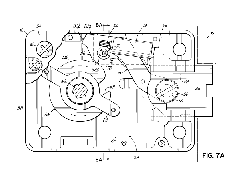
[0026] FIGS. 7A-7D are front plan views showing the device of FIG. 1
and coaction of a variety of elements at various stages as the lock bolt moves
between locked and unlocked positions.
[0027] FIGS. 8A-8D are cross-sectional views taken along section line
8A-8A through 8D-8D of FIGS. 7A-7D showing a relock device of the device of
FIG. 1.
[0028] FIG. 9 is a perspective view of the motor configuration
according
to the invention.
Detailed Description of the Drawings
[0029] This detailed description generally relates to the field of
lock
security. Specifically, a lock configuration is implemented for use in safe
containers and other security structures or areas in order to protect items of
extremely sensitive nature and/or of high proprietary value from access to
unauthorized individuals. For example, the lock configuration may be
implemented in a safe container that is located in a high level security zone
in
which unauthorized individuals may be aware that the location is housing
several safe containers that may be protecting items that are coveted by the
unauthorized individuals. The lock configuration is a configuration that
remains
in a locked state preventing access to the safe container and/or other
security
structures or areas and transitions to the unlocked state when instructed by
the
authorized individual.
[0030] In order to access the items housed in the safe container and
protected by the lock configuration, authorized individuals that have
authorization to access the protected items housed by the safe container may
enter a predetermined combination code into the lock configuration that when
entered correctly may unlock the lock configuration and allow access into the
safe container to the authorized individuals. The predetermined combination
code may be a predetermined sequence of characters that when entered by an
authorized individual triggers the lock configuration to transfer from the
locked
state to the unlocked state and allow access into the safe container. Unless
the
-8-
CA 03065310 2019-11-27
WO 2018/222817
PCT/US2018/035309
predetermined combination code is correctly entered into the lock
configuration,
the lock configuration may remain in the locked state and prevent access into
the safe container.
[0031] However, as noted above, unauthorized individuals that do not
have authorization to access the protected items housed by the safe container
may be aware of the location of the safe container and that the safe container
is
protecting items that are coveted by the unauthorized individuals. Such
unauthorized individuals may attempt to determine the predetermined
combination code as entered into the lock configuration by authorized
individuals. For example, an unauthorized individual may casually observe the
authorized individual enter the predetermined combination code into the lock
configuration without the knowledge of the authorized individual. Conventional
locking mechanisms, such as a conventional push button lock, provide the
unauthorized individual an opportunity to determine the predetermined
combination code as the authorized individual enters the predetermined
combination code into the conventional locking mechanism. In such an
example, as the authorized individual presses each button of the push button
lock in the proper sequence of the predetermined combination code, the
unauthorized individual may casually observe and record each button pressed
by the authorized individual in the proper sequence without the knowledge of
the authorized individual to determine the predetermined combination code.
[0032] Further, various applications of protecting safe containers
from
unauthorized access may require that the lock configuration satisfy a
specified
physical footprint. For example, standard safe containers have a standardized
physical footprint that the lock configuration is to satisfy without
encroaching
beyond the physical footprint. Typically, as the sophistication of a
conventional
locking mechanism increases, the size of the physical footprint of the
conventional locking mechanism also increases. For example, the amount of
power required for a conventional sophisticated locking mechanism
significantly
increases and in order to provide adequate power, the physical footprint of
the
conventional sophisticated locking mechanism also increases in order to
provide adequate power via a large battery and so on.
[0033] The lock configuration discussed in detail below implements an
active touchscreen that may enable the authorized individual to interact with
the
lock configuration. The lock configuration may adjust the characters displayed
-9-
CA 03065310 2019-11-27
WO 2018/222817
PCT/US2018/035309
by the active touchscreen such that the position of the characters and/or the
actual characters displayed by the active touchscreen may change. In
changing the position of the characters and/or the actual characters displayed
by the active touchscreen, the capability of the unauthorized individual to
determine the predetermined combination code entered by the authorized
individual may be greatly diminished.
[0034] For example, the unauthorized individual may observe that the
individual entered the predetermined combination code via the active
touchscreen with each character positioned in a first position on the active
touchscreen when the authorized individual entered the predetermined
combination code. However, the lock configuration may adjust each character
displayed by the active touchscreen to a second position when the
unauthorized individual attempts to enter the predetermined combination code.
The unauthorized individual may then fail to enter the correct predetermined
combination code with each character positioned in a different position in the
second position as compared to the position of each character in the first
position when the authorized individual attempted to enter the predetermined
combination code. Thus, the active touchscreen may provide increased
sophistication to the lock configuration in preventing unauthorized
individuals
from obtaining the predetermined combination code while casually observing
the authorized individual enter the predetermined combination code.
[0035] The lock configuration discussed below also implements an
internal generator that is internal to the lock configuration to generate
power to
power the active touchscreen as well as providing power to the bolt retraction
mechanism to transition the bolt retraction mechanism between the locked state
and the unlocked state, accordingly. The generator enables power to be
provided to the lock configuration while maintaining the physical footprint
typically implemented by safe containers. The generator may generate power
when the authorized user moves a power crank associated with the lock
configuration. The power crank initiates a gear train included in the lock
configuration when moved and the movement of the gear train may initiate the
generator to generate power that may then be consumed by the lock
configuration. The lock configuration may also include solar cells that
capture
solar energy that is then converted to power that may also be consumed by the
lock configuration. Thus, the lock configuration may generate sufficient power
-10-
CA 03065310 2019-11-27
WO 2018/222817
PCT/US2018/035309
without the need of large batteries and/or other power sources to power the
active touchscreen, the bolt retraction mechanism, and/or each of the other
features of the lock configuration and thereby maintaining the physical
footprint
of the lock configuration.
[0036] In the Detailed Description herein, references to "one
embodiment", "an embodiment," etc., indicate that the embodiment described
may include a particular feature, structure, or characteristic, but every
embodiment may not necessarily include the particular feature, structure, or
characteristic. Moreover, such phrases are not necessarily referring to the
same embodiment. Further, when a particular feature, structure, or
characteristic may be described in connection with an embodiment, it may be
within the knowledge of one of skilled in the art to effect such feature,
structure,
or characteristic in connection with other embodiments whether or not
explicitly
described.
[0037] The following detailed description refers to the accompanying
drawings that illustrate exemplary embodiments. Other embodiments are
possible, and modifications can be made to the embodiments within the spirit
and scope of this description. Those skilled in the art with access to the
teachings provided herein will recognize additional modifications,
applications,
and embodiments within the scope thereof and additional fields in which
embodiments which would be of significant utility. Therefore, the detailed
description is not meant to limit the embodiments described below.
[0038] FIG. 1 is a diagram of a touchscreen lock configuration 10 for
preventing unwanted opening of a locked enclosure and has an external user-
accessible hub 12 conveniently provided with an active touchscreen 14. The
hub 12 is attached to the casing 18 in any known manner that enables an
authorized individual to interface with the hub 12 and have the lock body
enclosed by the casing 18 to respond by having the bolt 22 move between the
locked and the unlocked positions accordingly as would be appreciated by one
having skilled in the relevant art given the description herein. For example,
the
hub 12 may be directly attached to the casing 18. In another example, the
access apparatus such as a door may be disposed between the hub 12 and the
casing 18.
[0039] As noted above, the touchscreen lock configuration 10 may
enable the authorized user to engage the touchscreen lock configuration 10 via
-11-
CA 03065310 2019-11-27
WO 2018/222817
PCT/US2018/035309
the active touchscreen 14. The touchscreen lock configuration 10 may adjust
the position of each of the characters displayed by the active touchscreen 14
as
well as adjusting the actual characters that are displayed by the active
touchscreen 14 where the active touchscreen 14 may display characters with
changed positions and/or changed characters actually displayed by the active
touchscreen 14. In doing so, the touchscreen lock configuration 10 may
prevent the unauthorized individual from casually observing the authorized
individual enter the predetermined combination code without the knowledge of
the authorized individual and determining the predetermined combination from
observing the authorized individual entering the predetermined combination
code.
[0040] A character may be any type of alphanumeric character and/or
symbol that may be included in the predetermined combination code. Each of
the characters may then be recognized by the authorized individual such that
when the character is displayed by the active touchscreen 14 the authorized
individual may recognize the character as being included in the predetermined
combination code. The authorized individual may then select the character and
the subsequent characters included in the predetermined combination code to
transition the touchscreen lock configuration 10 into the unlocked state.
[0041] In an embodiment, the touchscreen lock configuration 10 may
adjust each of the characters displayed by the active touchscreen 14 such that
each of the characters are displayed in a different position each time an
individual attempts to enter the predetermined combination code. For example,
the first time that an individual attempts to enter the predetermined
combination
code, each of the characters may be displayed in a first set of respective
positions 16(a-n), where n is an integer equal to or greater than one. Then
the
second time that an individual attempts to enter the predetermined combination
code each of the characters may be displayed in a second set of respective
positions 16(a-n) where each of the positions 16(a-n) for each of the
respective
characters between the first set and the second set have changed.
[0042] In an embodiment, the touchscreen lock configuration 10 may
adjust the actual characters displayed by the active touchscreen 14 such that
different characters are displayed each time an individual attempts to enter
the
predetermined combination code. For example, the predetermined combination
code is 5 0 7 5. The first time that an individual attempts to enter the
-12-
CA 03065310 2019-11-27
WO 2018/222817
PCT/US2018/035309
predetermined combination code, each of the characters displayed by the
respective positions 16(a-n) include AB50 D E75W X. Then the second
time each of the characters displayed by the respective positions 16(a-n)
include 2 5V*OQS7! 5.
[0043] Rather than have the unauthorized individual be able to
casually
observe the authorized individual adjust a conventional dial locking mechanism
by tracking the direction of each turn of the dial as well as the amount of
turns
as well as the character that each turn ends on, the touchscreen lock
configuration 10 may prevent the unauthorized individual from being able to do
so by changing the position of the characters as well as the characters
themselves that are displayed each time access to the touchscreen lock
configuration 10 is attempted. The touchscreen lock configuration 10 may
adjust the characters displayed by the active touchscreen 14 in any manner and
at any frequency of attempts to access the touchscreen lock configuration 10
as
would be appreciated by one having skilled in the relevant art given the
description herein.
[0044] As noted above, the touchscreen lock configuration 10 may also
include an internal generator to provide sufficient power to the active
touchscreen 14, the bolt retraction mechanism, and each of the other features
of the touchscreen lock configuration 10 without expanding beyond the physical
footprint of the touchscreen lock configuration 10. Rather than incorporate
large power sources, the touchscreen lock configuration includes 10 a gear
assembly that is coupled to the internal generator as well as the power crank
20. Each time that the authorized individual requests to power up the
touchscreen lock configuration 10, the authorized individual applies force to
the
power crank 20 and moves the power crank 20 in a manner that rotates the
gear assembly. Each time the authorized individual moves the power crank 20
and rotates the gear assembly, the internal generator generates power and
supplies the power to the touchscreen lock configuration 10. The authorized
individual may continue to move the power crank 20 until the internal
generator
has generated sufficient power to for the touchscreen lock configuration 10 to
adequately operate.
[0045] The touchscreen lock configuration 10 may also include a
battery
bank 26. In addition to the power generated by the internal generator, the
battery bank 26 may also provide power to assist the touchscreen lock
-13-
CA 03065310 2019-11-27
WO 2018/222817
PCT/US2018/035309
configuration 10 to adequately operate. Depending on the complexity of the
gear train, the quantity of times required to move the power crank 20 to have
the internal generator generate sufficient power for the touchscreen lock
configuration 10 to adequately operate may increase. Rather than have the
authorized individual move the power crank 20 an increased quantity of times,
the battery bank 26 may also provide power so that the authorized individual
may move the power crank a minimum amount of times to have the internal
generator generate power that is then supplemented with power provided by
the battery bank 26. The touchscreen lock configuration 10 may operate off of
power solely generated by the internal generator, solely generated by the
battery bank 26, and/or a combination of the internal generator and the
battery
bank 26 as would be appreciated by one having skilled in the relevant art
given
the description herein.
[0046] The touchscreen lock configuration 10 may also include a
plurality
of solar cells 24 to assist in providing power to the touchscreen lock
configuration 10. Each of the solar cells 24 may absorb solar energy and then
charge a capacitor bank that includes one or more capacitors with the absorbed
energy. As the solar cells 24 absorb solar energy, each of the capacitors
included in capacitor bank is charged until each of the capacitors included in
the
capacitor bank are charged to capacity. The capacitor bank may then
discharge the stored power when the individual moves the power crank 20 to
supplement the power generated by the internal generator such that the
authorized individual may move the power crank 20 a minimum quantity of
times to provide sufficient power to the touchscreen lock configuration 10 to
adequately operate. In an embodiment, each of the solar cells may be
positioned on the hub 12. However, the solar cells may be positioned
anywhere on the touchscreen lock configuration and/or coupled to the
touchscreen lock configuration 10 to adequately absorb solar energy and
charge the capacitor bank as would be appreciated by one having skilled in the
relevant art given the description herein.
[0047] FIG. 2 is an exploded view of the hub 12 for generating power
for
the touchscreen lock configuration 10. As noted above, the authorized
individual may move the power crank 20 in order to activate the touchscreen
lock configuration 10. The power crank 20 is coupled to the generator
configuration 30 and the gear train 28 via the rotatable hub 32. Each time the
-14-
CA 03065310 2019-11-27
WO 2018/222817
PCT/US2018/035309
authorized individual moves the power crank 20, the gear train 28 rotates as
well as the generator configuration 30. With each rotation of the generator
configuration 30 and the gear train 28, the generator configuration 30
generates
power that is to be consumed by the touchscreen lock configuration 10.
[0048] In an embodiment, the authorized individual may move the power
crank 20 in a downward direction 34. Each time the authorized individual
moves the power crank 20 in the downward direction 34, the gear train 28
rotates as well as the generator configuration 30 resulting in power generated
by the generator configuration 30. In another embodiment, the authorized
individual may move the power crank 20 in an upward direction 36. Each time
the authorized individual moves the power crank 20 in the upward direction 36,
the gear train 28 rotates as well as the generator configuration 30 resulting
in
power generated by the generator configuration 30. In another embodiment,
the authorized individual may move the power crank 20 in the downward
direction 34 and the upward direction 36. Each time the individual moves the
power crank 20 in the downward direction 34 and the upward direction 36, the
gear train 28 rotates as well as the generator configuration 30 resulting in
power
generated by the generator configuration 30.
[0049] The quantity of times that the authorized individual is to
move the
power crank 20 to generate sufficient power for the touchscreen lock
configuration 10 to adequately operate is dependent upon the complexity of the
gear train 28. As the complexity of the gear train 28 increases, the quantity
of
times that the authorized individual is to move the power crank 20 to generate
sufficient power for the touchscreen lock configuration 10 to adequately
operate
decreases. As the complexity of the gear train 28 decreases, the quantity of
times that the authorized individual is to move the power crank 20 to generate
sufficient power for the touchscreen lock configuration 10 to adequately
operate
increases.
[0050] For example, the individual may have to move the power crank
20
in the downward direction 34 a single time and in the upward direction 36 a
single time to generate sufficient power for the touchscreen lock
configuration
to adequately operate when the gear train 28 is of increased complexity. In
another example, the individual may have to move the power crank 20 in the
downward direction 34 five times and in the upward direction 36 five times to
generate sufficient power for the touchscreen lock configuration 10 to
-15-
CA 03065310 2019-11-27
WO 2018/222817
PCT/US2018/035309
adequately operate when the configuration is of decreased complexity.
[0051] Typically, the cost of the gear train 28 increases as the
complexity
increases. Thus, the power generated by the generator configuration 30 may
be supplemented with the power provided by the solar cells 24 and the power
provided by the battery bank 26 when the gear train 28 is of decreased
complexity. Rather than have the authorized individual move the power crank
20 several times when the gear train 28 is of decreased complexity, the
authorized individual may move the power crank 20 a time or two to have the
generator configuration 30 generate power and then supplement that power
with the power provided by the solar cells 24 and the battery bank 26. In
doing
so, sufficient power may be provided to the touchscreen lock configuration 10
to
adequately operate with the use of large external power sources.
[0052] In an embodiment, the generator configuration 30 may be
positioned in the hub 12 in front of the casing 18 relative to a front view of
the
touchscreen lock configuration 38. In another embodiment, the generator
configuration 30 may be positioned behind the casing 18 relative to a front
view
of the touchscreen lock configuration 38. In another embodiment, a first
generator may be positioned in the hub 13 in front of the casing 18 and a
second generator may be positioned behind the casing 18 relative to a front
view of the touchscreen lock configuration 38. In such an embodiment, wireless
communication between the first generator and the second generator may
occur via infrared signals transmitted between the first generator and the
second generator. In another embodiment, a wired interface may exist between
the first generator and the second generator.
[0053] FIG. 3 is a schematic view of the touchscreen lock
configuration
38. As noted above, the generator configuration 30 may generate power upon
the movement of the power crank 20 by the authorized individual. With each
movement of the power crank 20 by the authorized individual, the power
generated by the generator configuration 30 increases. The generator
configuration 30 may provide sufficient power for the touchscreen lock
configuration 38 to adequately operate after the individual has moved the
power
crank 20 a sufficient quantity of times to generate the sufficient amount of
power. The solar cells 24 may absorb solar energy and charge the capacitor
bank 42 to supplement the power generated by the generator configuration 30.
The battery bank 26 may also supplement the power generated by the
-16-
CA 03065310 2019-11-27
WO 2018/222817
PCT/US2018/035309
generator configuration. Thus, the touchscreen lock configuration 38 is self-
powered in that power is provided by the generator configuration 30 such that
large external power sources are not needed to provide sufficient power for
the
touchscreen lock configuration 38 to adequately operate while remaining within
the physical footprint of the touchscreen lock configuration 38.
[0054] The controller 40 may monitor the power generated by the
generator configuration 30. The controller 40 may monitor the power generated
by the generator configuration 30 to determine when the power generated by
the generator configuration 30 exceeds the threshold. The threshold is the
amount of power required by the touchscreen lock configuration 38 to
adequately operate such that each of the features of the touchscreen lock
configuration 38 may be provided to the authorized individual when needed.
For example, the threshold is the amount of power required by the touchscreen
lock configuration 38 to adequately operate the active touchscreen 14 and
provide each of the features displayed by the active touchscreen 14, to
adequately operate the motor drive circuitry 44 of the bolt retraction
mechanism
and so on.
[0055] The controller 40 includes a processor, a memory, and a
network
interface, herein after referred to as a computing device or simply
"computer".
The controller may 40 may be any type of processing (or computing device).
For example, the controller 40 may include a data information system, data
management system, web server, and/or file transfer server. The controller 40
may also be a workstation, mobile device, computer, cluster of computers, set-
top box or other computing device. In an embodiment, multiple modules may
be implemented on the same computing device. In another embodiment,
multiple modules may be implemented on different computing devices. Such a
computing device may include software, firmware, hardware, or a combination
thereof. Software may include one more applications on an operating system.
Hardware can include, but is not limited to, a processor, memory, and/or
graphical user interface display.
[0056] As the controller 40 monitors the power generated by the
generator configuration 30, the controller 40 may maintain the active
touchscreen 14, the motor drive circuitry 44 of the bolt retraction mechanism
and/or each of the other features of the touchscreen lock configuration 38 in
the
deactivated state in order to conserve power consumption when the power
-17-
CA 03065310 2019-11-27
WO 2018/222817
PCT/US2018/035309
generated by the generator configuration 30 remains below the threshold. After
the power generated by the generator configuration 30 exceeds the threshold,
the controller 40 may then activate the active touchscreen 14, the motor drive
circuitry 44 of the bolt retraction mechanism and/or each of the other
features of
the touchscreen lock configuration 38. For example, the controller 40 may
instruct the active touchscreen 14 to display the characters for the
authorized
individual to select appropriate characters to enter the predetermined
combination code as well as display that the bolt 22 is in the "LOCKED"
position.
[0057] The solar cells 24 capture solar energy from a solar source,
such
as a light source. The solar cells 24 may include a single and/or multiple
solar
cells that convert the solar energy into captured power that is stored by the
capacitor bank 42. The solar cells 24 may capture the solar energy when the
solar source is available and is radiating the solar energy in a sufficient
manner
for the solar cells 24 to capture. The solar cells 24 may include photovoltaic
solar panels categorized as but not limited to mono-crystalline silicon, poly-
crystalline silicon, amorphous silicon, cadmium telluride, copper indium
selenide, thin-film layers, organic dyes, organic polymers, nanocrystals
and/or
any other type of photovoltaic solar panels that will be apparent to those
skilled
in the relevant art(s) without departing from the spirit and scope of the
disclosure. The solar cells 24 may also be any shape and/or size that are
sufficient to capture the solar energy that will be apparent to those skilled
in the
relevant art(s) without departing from the spirit and scope of the disclosure.
[0058] The controller 40 may also monitor the charge of the capacitor
bank 42 in addition to the power generated by the generator configuration 30
to
determine whether collectively the power generated by the generator
configuration 30 and the charge of the capacitor bank 42 has exceeded the
threshold. As the charge of the capacitor bank 42 and the power generated by
the generator configuration 30 exceeds the threshold, the controller 40 may
then activate the active touchscreen 14, the motor drive circuitry 44 of the
bolt
retraction mechanism and/or each of the other features of the touchscreen lock
configuration 38. For example, the controller 40 may instruct the motor drive
circuitry 44 of the bolt retraction mechanism to transfer from the locked
position
to the unlocked position when the authorized individual correctly enters the
predetermined combination code via the active touchscreen 14 as well as
-18-
CA 03065310 2019-11-27
WO 2018/222817
PCT/US2018/035309
instruct the active touchscreen 14 to display that the bolt 22 is in the
"UNLOCKED" position.
[0059] In an embodiment, the solar cells 24 may capture sufficient
solar
energy from a solar source for the touchscreen lock configuration 38 to
adequately execute each of the features as requested by the authorized
individual. In doing so, the solar cells 24 may convert the solar energy to
direct
current (DC) power and store the DC power in a battery bank, such as the
battery bank 26. The battery bank may have increased capacity as compared
to the capacitor bank 42 to store the increased amount of DC power converted
from the solar energy captured by the solar cells 24. The controller 40 may
then operate the touchscreen lock configuration 38 based on the DC power
stored in the battery bank as provided by the solar cells 24.
[0060] The battery bank 26 stores power. The battery bank 26 may
store
the power until requested by the controller 40 to provide the power. The
battery
bank 26 may include one or more lithium ion phosphate (LiFePO4) and/or one
or more lead acid cells. However, this example is not limiting, those skilled
in
the relevant art(s) may implement the battery bank 26 using other battery
chemistries without departing from the scope and spirit of the present
disclosure. The one or more cells of the battery bank 26 convert chemical
energy into electrical energy via an electromechanical reaction.
[0061] The controller 40 may also monitor the power level of the
battery
bank 26 in addition to the charge of the capacitor bank 42 and the power
generated by the generator configuration 30 to determine whether collectively
the power generated by the generator configuration 30, the charge of the
capacitor bank 42, and the power level of the battery bank 26 has exceeded the
threshold. As the power level of the battery bank 26, the charge of the
capacitor bank 42 and the power generated by the generator configuration 30
exceeds the threshold, the controller 40 may then activate the active
touchscreen 14, the motor drive circuitry 44 of the bolt retraction mechanism
and/or each of the other features of the touchscreen lock configuration 38.
For
example, the controller 40 may instruct the active touchscreen 14 to change
the
display to a different menu as requested by the authorized individual.
[0062] The controller 40 may determine which power is to be consumed
by the touchscreen lock configuration 38. The controller 40 may determine
whether the power generated by the generator configuration 30, the power
-19-
CA 03065310 2019-11-27
WO 2018/222817
PCT/US2018/035309
stored in the capacitor bank 42, and/or the power stored in the battery bank
26
is to be consumed based on the power levels of the generator configuration 30,
the capacitor bank 42, and the battery bank 26 as well as the features that
the
authorized individual is requesting. The controller 40 may assess the power
required to adequately provide the requested features to the authorized
individual as well as the respective power levels of the generator
configuration
30, the capacitor bank 42, and the battery bank 26 to determine which of the
power sources and/or combination thereof are to be accessed to execute
requested features.
[0063] For example, the controller 40 may assess that the touchscreen
lock configuration 38 is currently in a dormant state and not engaged by the
authorized individual. In doing so, the controller 40 may assess that a low
level
of power is required and that the capacitor bank 42 currently has sufficient
charge to power the active touchscreen 14 such that the active touchscreen 14
displays "LOCKED". The controller 40 may then have the capacitor bank 42
provide power to the active touchscreen 14 such that the active touchscreen 14
displays "LOCKED" without having to incorporate the power generated by the
generator configuration 30 and the power stored by the battery bank 26.
[0064] In another example, the controller 40 may asses that the
authorized individual is requesting to engage the active touchscreen 14 as
well
as requesting a transfer of access data from the touchscreen lock
configuration
38 to the remote computing device 50. In doing so, the controller 40 may
assess that high level of power is required and that the power generated by
the
generator 30 is insufficient to execute the required features by the
authorized
individual. However, the controller 40 may determine that collectively the
power
generated by the generator configuration 30, the current charge of the
capacitor
bank 42, and the power stored in the battery bank 26 is sufficient to execute
the
transfer of access data to the remote computing device 50. The controller 40
may then have the generator configuration 30, the capacitor bank 42, and the
battery bank 26 provide power to execute the transfer of access data.
[0065] The touchscreen lock configuration 38 may incorporate any type
of power source and/or combination of power sources to execute any feature
and/or combination of features as would be appreciated by one having skilled
in
the relevant art given the description herein. For example, any feature and/or
combination of features discussed in detail below may be executed by the
-20-
CA 03065310 2019-11-27
WO 2018/222817
PCT/US2018/035309
controller 40 via the consumption of power provided by one or more generators,
such as the generator configuration 30. In another example, any feature and/or
combination of features discussed herein may be executed by the controller 40
via the consumption of power provided by one or more batteries, such as the
battery bank 26. In another example, any feature and/or combination of
features discussed in detail below may be executed by the controller via the
consumption of power provided by solar power, such as the solar cells 24. As
discussed in detail above, the controller 40 may also assess each feature
and/or combination of features discussed in detail below that is to be
executed
by the touchscreen lock configuration 38 to determine the particular power
source that is to provide the power for the execution of the particular
feature
and/or combination of features.
[0066] As noted above, the touchscreen lock configuration 38 includes
the active touchscreen 14. The active touchscreen 14 is a touchscreen that
enables the authorized individual to interact with the touchscreen lock
configuration 38. The active touchscreen 14 is not limited to a single
screenshot that is displayed to the authorized individual. Rather, the active
touchscreen 14 may have several different screenshots that may be displayed
to the authorized individual with each of the different screenshots providing
different features for the authorized individual to select. The authorized
individual may navigate through each of the different screenshots by selecting
different menus provided by the active touchscreen 14 with each of the
different
menus having different features to select. The authorized individual may also
navigate through each of the screenshots by incorporating arrow buttons and so
on that enables the authorized individual to change the screenshot displayed
by
the active touchscreen 14. The authorized individual may also navigate through
each of the screenshots by swiping across the active touchscreen 14, such as
but not limited to swiping from the left to the right of the active
touchscreen 14
and/or from the right to the left of the active touchscreen 14.
[0067] For example, the active touchscreen 14 is not limited to
simply
displaying the amount of characters that correspond to the amount of positions
16(a-n) displayed by the active touchscreen 14. In FIG. 1, the active
touchscreen 14 displays ten different positions 16(a-n) in which each of the
different positions 16(a-n) may display a different character for the
authorized
individual to select from when entering the predetermined combination code.
-21-
CA 03065310 2019-11-27
WO 2018/222817
PCT/US2018/035309
However, rather than limiting the amount of characters displayed to the
authorized individual to ten, the authorized individual may scroll through and
change the screenshot displayed by the active touchscreen 14 such that
another ten characters are displayed to the authorized individual. The
authorized individual may scroll through and change the screenshot displayed
by the active touchscreen 14 to such that another ten characters are displayed
to the authorized individual.
[0068] In another example as shown in FIG. 1, the active touchscreen
14
displays ten different positions 16(a-n) for four different screenshots where
the
characters displayed in each of the ten different positions 16(a-n) differ in
each
of the four different screenshots. A first screenshot may display the NUMBER
characters of 0 through 9 in each of the ten different positions 16(a-n). The
first
screenshot may be the default screenshot where upon startup of the
touchscreen lock configuration 38, the initial screenshot displayed by the
active
touchscreen 14 may be the screenshot displaying the NUMBER characters 0
through 9. Each time that the active touchscreen 14 displays the first
screenshot displaying the NUMBER characters 0 through 9, the position 16(a-n)
of each of the NUMBER characters 0 through 9 may be randomly changed
such that the positon 16(a-n) of each of the NUMBER characters 0 through 9
displayed by the active touchscreen 14 changes.
[0069] The second screenshot that is displayed by the active
touchscreen 14 may display the LETTER characters A through J in each of the
ten different positions 16(a-n). The second screenshot may display the
LETTER characters A through J as uppercase letters, lowercase letters, and/or
any combination thereof. The authorized individual may transition the LETTER
characters A through J that are displayed as uppercase letters and/or
lowercase letters via the active touchscreen display 14. Each time that the
active touchscreen 14 displays the second screenshot displaying the LETTER
characters A through J, the position 16(a-n) of each of the LETTER characters
A through J may be randomly changed such that the position 16(a-n) of each of
the LETTER characters A through J displayed by the active touchscreen 14
changes.
[0070] The third screenshot that is displayed by the active
touchscreen
14 may display the LETTER characters K through T in each of the ten different
positions 16(a-n). The third screenshot may display the LETTER characters K
-22-
CA 03065310 2019-11-27
WO 2018/222817
PCT/US2018/035309
through T as uppercase letters, lowercase letters, and/or any combination
thereof. The authorized individual may transition the LETTER characters K
through T as uppercase letters and/or lowercase letters via the active
touchscreen display 14. Each time that the active touchscreen 14 displays the
third screenshot displaying the LETTER characters K through T, the position
16(a-n) of each of the LETTER characters K through T may be randomly
changed such that the position 16(a-n) of each of the LETTER characters K
through T displayed by the active touchscreen 14 changes.
[0071] The fourth screenshot that is displayed by the active
touchscreen
14 may display the LETTER characters U through Z in each of the ten different
positons 16(a-n). The fourth screenshot may display the LETTER characters U
through Z as uppercase letters, lowercase letters, and/or any combination
thereof. The authorized individual may transition the LETTER characters U
through Z as uppercase letters and/or lowercase letters via the active
touchscreen display 14. Each time the active touchscreen 14 displays the
fourth screenshot displaying the LETTER characters U through Z, the position
16(a-n) of each of the LETTER characters U through Z may be randomly
changed such that the position 16(a-n) of each of the LETTER characters U
through Z displayed by the active touchscreen 14 changes.
[0072] The active touchscreen 14 may also display SPECIAL characters
in the positions 16(a-n) where the SPECIAL characters include characters that
are not NUMBER characters and/or LETTER characters such as but not limited
to characters of @, $ # and so on. Each time the active touchscreen 14
displays the screenshot displaying the SPECIAL characters, the position 16(a-
n) of each of the SPECIAL characters may be randomly changed such that the
position 16(a-n) of each of the SPECIAL characters displayed by the active
touchscreen 14 changes. The active touchscreen 14 may also display
CHINESE and/or ARABIC characters in the positons 16(a-n).
[0073] In such an example, the categorizing of characters by
different
screenshots enables the position 16(a-n) of each of the characters to be
changed per screenshot. Rather than the active touchscreen 14 displaying a
large quantity of characters at a time and then randomly changing the position
16(a-n) of each of the characters, a lesser quantity of characters may be
displayed in each of the different screenshots with the position 16(a-n) of
each
of the characters displayed in each of the different screenshots being
changed.
-23-
CA 03065310 2019-11-27
WO 2018/222817
PCT/US2018/035309
This may enable the authorized individual to have less difficulty in
identifying
each of the characters included in the predetermined combination each time the
authorized individual attempts to enter the predetermined combination code.
For example, the authorized individual may identify the position 16(a-n) of
two
characters included in the predetermined combination code as displayed in
each of the four different screenshots each displaying ten characters in ten
positions 16(a-n) rather than having to identify the position 16(a-n) of all
eight
characters as display amongst forty different characters displayed in a single
screenshot.
[0074] Further, the flexibility in displaying lesser quantity of
characters
that is spread across different screenshots enables a predetermined
combination code to be implemented that incorporates a large quantity of
characters to decrease the risk of the unauthorized individual from
determining
the predetermined combination code while also enabling a predetermined
combination code to be selected that may be easily remembered by the
authorized individual. For example, a forty-three character predetermined
combination code that includes a sequence of characters that has no relation
to
each other may be difficult for the authorized individual to remember.
However,
a forty-three character predetermined combination code that includes the
sequence of characters of "The quick brown fox jumps over the lazy dog 2 @
3:00 PM." may be identified by the authorized individual as a sentence that
the
authorized individual may memorize as opposed to a string of forty-three
characters. The likelihood of the unauthorized individual from determining the
predetermined combination code is decreased due to the increased quantity of
characters included in the predetermined combination code while the ease of
the authorized individual in remembering the predetermined combination code
is also increased.
[0075] The characters included in a predetermined combination code
and
displayed in each of the different positions 16(a-n) and different screenshots
by
the active touchscreen 14 may include any quantity of characters and displayed
in any position 16(a-n) amongst any of the different screens shots as would be
appreciated by one having skilled in the relevant art given the description
herein. The controller 40 may be programmed such that the predetermined
combination code may include any combination of characters that is to be
entered in any designated sequence as required by the controller 40. The
-24-
CA 03065310 2019-11-27
WO 2018/222817
PCT/US2018/035309
controller 40 may also be programmed to prevent different sequences of
characters such as "00 00 00" that may be highly susceptible to being
determined by the unauthorized individual from being included in the
predetermined combination code. The controller 40 may be programmed to
include any type of rule associated with the types of characters and/or
sequence of characters that may be included in the predetermined combination
code as would be appreciated by one having skilled in the relevant art given
the
description herein.
[0076] In doing so, the characters included in the predetermined
combination code are not limited to being selected from ten different
characters
and are also not limited to being displayed in in a single screenshot as
displayed by the active touchscreen 14. The first and second character may be
displayed in the first screenshot along with eight other characters and then
the
authorized individual may then have to scroll to a second screenshot that
displays the remaining characters along with eight different characters not
previously displayed in the first screenshot thereby greatly increasing the
security of the touchscreen lock configuration 38.
[0077] In an embodiment, the authorized individual may directly touch
the
active touchscreen 14 as the authorized individual navigates through the
features of the touchscreen lock configuration 14 and selects the features
that
the authorized individual requests to have executed by the touchscreen lock
configuration 38. In another embodiment, the authorized individual may
navigate through the features displayed by the active touchscreen 14 via a
knob. The authorized individual may navigate through the features displayed
by the active touchscreen 14 in any manner that enables the authorized
individual to access each of the features of the touchscreen lock
configuration
38 as would be appreciated by one having skilled in the relevant art given the
description herein. The active touchscreen 14 may be any type of display
device including but not limited to a touchscreen display, a liquid crystal
display
(LCD) screen, an electrophoretic display, and/or any other type of display
that
will be apparent from those skilled in the relevant art(s) without departing
from
the spirit and scope of the present disclosure. The active touchscreen 14 may
also have low power requirements.
[0078] In an embodiment, the active touchscreen 14 may include an
electrophoretic display, such as but not limited to an Einke display. An
-25-
CA 03065310 2019-11-27
WO 2018/222817
PCT/US2018/035309
electrophoretic display may include numerous microcapsules which each
microcapsule including positively charged white particles and negatively
charged black particles that are encapsulated in a clear fluid. As a positive
voltage is applied to a particular microcapsule, the white particles rise to
the
surface of the display. As a negative voltage is applied to a particular
microcapsule, the black particles rise to the surface of the display providing
a
representation as a black pigment appearing on the display that appears to be
black ink on the display.
[0079] The electrophoretic display, or any other electronic display
technology used for carrying out aspects of this invention, may have minimal
power requirements in that the display consumes no power unless controller 40
changes the image that is displayed. The electrophoretic display does not
require continuous signal controls to maintain the image that is displayed by
the
electrophoretic display and thereby does not require power to maintain the
image that is displayed. It will be appreciated that any other display which
is
used in connection with a lock consistent herewith, including but not limited
to
an electrophoretic display, which functions in this general manner may be used
for purposes of achieving similar capabilities in a low power lock such as the
self-powered type disclosed herein. For example, after the authorized
individual has transferred the touchscreen lock configuration 38 into the
locked
state, the controller instructs the electrophoretic display to change the
content
that is displayed to "LOCKED". The electrophoretic display may then continue
to display "LOCKED" without consuming any power until the electrophoretic
display is requested to change the content that is displayed by the controller
40.
In doing so, the electrophoretic display may clearly display that the status
of the
touchscreen lock configuration 38 without consuming any power when the
touchscreen lock configuration 38 is not engaged by the authorized individual.
[0080] The amount of power required to change the image that is
displayed by the electrophoretic display as requested by the controller 40 is
minimal. The controller 40 may request that different partitions of the
electrophoretic display to change the color that is displayed by the
microcapsules included in each different partition from white to black and/or
black to white depending on the image that the controller 40 requests the
electrophoretic display to display. As noted above, a positive voltage is
applied
to a particular microcapsule to have the white particles included in the
-26-
CA 03065310 2019-11-27
WO 2018/222817
PCT/US2018/035309
microcapsule to rise to the surface of the display thereby displaying a
"blank" in
the particular partition that includes the microcapsules that have received a
positive voltage. A negative voltage is applied to a particular microcapsule
to
have the black particles included in the microcapsule to rise to the surface
of
the display thereby displaying a "black pigment" in the particular partition
that
includes the microcapsules that have received the negative voltage.
[0081] The amount of positive voltage that is applied to the
particular
microcapsules to have the white particles rise to the surface rather than the
black particles and the amount of negative voltage that is applied to the
particular microcapsules to have the black particles rise to the surface
rather
than the white particles to change the image displayed by the electrophoretic
display is minimal. For example, controller 40 may request that the
electrophoretic display change from displaying the image of "LOCKED" to
"UNLOCKED".
[0082] In doing so, the controller 40 may apply a positive voltage to
the
partitions included in the electrophoretic display that have microcapsules
that
are to transition from having black particles at the surface to having white
particles at the surface such that the respective partitions transition from
displaying "black pigment" to displaying a "blank" on the electrophoretic
display.
The controller 40 may also display a negative voltage to the partitions
included
in the electrophoretic display that have microcapsules that are to transition
from
having white particles at the surface to having black particles at the surface
such that the respective partitions transition from displaying a "blank" to
displaying a "black pigment". The amount of positive voltage and/or negative
voltage applied to the requested microcapsules to change the image displayed
be electrophoretic display from "LOCKED" to "UNLOCKED" may be as low as
3V at 40mA and could range up beyond 9V. The amount of voltage and/or
current to change the image displayed by the electrophoretic display may be
any voltage and/or current required to have the required microcapsules have
the appropriate black and/or white particles rise to the surface to change the
image as would be appreciated by one having skilled in the relevant art given
the description herein.
[0083] The electrophoretic display may be a reflective display in
that the
image displayed by the electrophoretic display may be viewed by the human
eye from the ambient light surrounding the electrophoretic display reflecting
-27-
CA 03065310 2019-11-27
WO 2018/222817
PCT/US2018/035309
from the electrophoretic display and received by the human eye. In doing so,
the electrophoretic display does not require a backlight to project light
through
the electrophoretic display such that the image is then received by the human
eye. In eliminating the need for a backlight, the electrophoretic display
consumes even less power in displaying the image such that the image is
adequately viewed by the human eye.
[0084] Thus, the active touchscreen 14 incorporated as an
electrophoretic display may have sufficient power provided by the generator
configuration 30 of the touchscreen lock configuration 38. In doing so, the
active touchscreen 14 may display each of the images as instructed by the
controller 40 to enable the authorized individual to adequately navigate
through
the active touchscreen 14 to satisfy the needs of the authorized individual in
interfacing with the touchscreen lock configuration 38 without requiring
additional power be provided by external power sources, thereby providing a
self-powered touchscreen lock configuration 38.
[0085] As noted above, the controller 40 may instruct the active
touchscreen 14 to display different characters each time the authorized
individual attempts to enter the predetermined combination code as well as
displaying the characters included in the predetermined combination code in
different positions with each attempt to enter the predetermined combination
code. In an embodiment, the controller 40 may incorporate a random number
generator that randomly selects the characters that are to be displayed by the
active touchscreen 14 as well as randomly selecting the position of the
characters included in the predetermined combination code. In another
embodiment, the controller 40 may have several different sequences stored
with each sequence including a different set of characters that are displayed
to
the authorized user as well as each sequence including a different position of
the characters included in the predetermined combination code. Each time the
authorized individual attempts to enter the predetermined combination code,
the
controller 40 may select a different sequence of characters that is to be
displayed to the authorized individual via the active touchscreen 14. The
controller 40 may determine the characters to be displayed as well as the
positioning of the characters included in the predetermined combination code
in
any manner that changes the characters displayed as well as the positioning of
the characters included in the predetermined combination code as would be
-28-
CA 03065310 2019-11-27
WO 2018/222817
PCT/US2018/035309
appreciated by one having skilled in the relevant art given the description
herein.
[0086] For example, the authorized individual may attempt to enter
the
predetermined combination code of 5 0 7 0 2 by moving the power crank 20.
The controller 40 may detect the movement of the power crank 20 from the
generation of power by the generator configuration 30. The controller may then
randomly select to display the following in the active touchscreen 14:
Q is positioned in position 16a
7 is positioned in position 16b
$ is positioned in position 16c
is positioned in position 16d
0 is positioned in position 16e
0 is positioned in position 16f
V is positioned in position 16g
G is positioned in position 16h
2 is positioned in position 16i
: is positioned in position in 16n
The authorized individual may then correctly press position 16d, position 16e,
position 16b, position 16f, and position 16i via the active touchscreen 14 to
enter the predetermined combination code of 5 0 7 0 2. The controller 40 then
instructs the touchscreen lock configuration 38 to transfer from the locked
state
to the unlocked state thereby unlocking the touchscreen lock configuration 38.
The controller 40 may then instruct the active touchscreen 14 to display
"UNLOCKED" indicating that the touchscreen lock configuration 38 is in the
unlocked state. The authorized individual may then engage the active
touchscreen 14 requesting that the touchscreen lock configuration 38 to
transition from the unlocked state to the locked state. The controller 40 may
then instruct the touchscreen lock configuration 38 to transfer from the
unlocked
state to the locked state thereby locking the touchscreen lock configuration
38.
The controller 40 may then instruct the active touchscreen to display "LOCKED"
indicating that the touchscreen lock configuration 38 is in the locked state.
[0087] The authorized individual may then attempt to enter the
predetermined combination code of 5 0 7 0 2 a second time by moving the
power crank 20 a second time following the locking of the touchscreen lock
configuration 38. The controller 40 may detect the movement of the power
-29-
CA 03065310 2019-11-27
WO 2018/222817
PCT/US2018/035309
crank 20 from the generation of power by the generator configuration 30. The
controller may then randomly select to display the following in the active
touchscreen 14:
2 is positioned in position 16a
W is positioned in position 16b
7 is positioned in position 16c
[ is positioned in position 16d
T is positioned in position 16e
8 is positioned in position 16f
is positioned in position 16g
0 is positioned in position 16h
1 is positioned in position 16i
0 is positioned in position in 16n
The authorized individual then correctly press position 16g, position 16h,
position 16c, position 16n, and position 16a via the active touchscreen 14 to
enter the predetermined combination code of 5 0 7 0 2. The controller 40 then
instructs the touchscreen lock configuration 30 from the locked state to the
unlocked state thereby unlocking the touchscreen lock configuration 38. The
controller 40 may then instruct the active touchscreen 14 to display
"UNLOCKED" indicating that the touchscreen lock configuration 38 is in the
unlocked state.
[0088] In doing so, an unauthorized individual that attempts to apply
a
fingerprint identification material on the active touchscreen 14 to determine
predetermined combination code by identifying the positions 16(a-n) of the
active touchscreen 14 that have fingerprints would be unsuccessful. The
random changing of the positions of the predetermined combination code as
displayed by the active touchscreen 14 enables the authorized individual to
select different positions of the predetermined combination code with each
attempt to unlock the touchscreen lock configuration 38. Thus, an unauthorized
individual attempting to identify the positions that have fingerprints would
be
unsuccessful in attempting to identify the predetermined combination code from
the fingerprints.
[0089] In an embodiment, the controller 40 may adjust the
predetermined
combination code on a periodic basis. The controller 40 may adjust the
predetermined combination code on a periodic basis when several different
-30-
CA 03065310 2019-11-27
WO 2018/222817
PCT/US2018/035309
authorized individuals have authorization to access the safe container and
particularly when the different authorized individuals may be limited to
accessing the safe container in a single instance. In doing so, the controller
40
may adjust the predetermined combination code on a periodic basis so that
individuals initially authorized to access the safe container and then have
that
authorization revoked cannot return to the safe container and correctly enter
the
predetermined combination code into the active touchscreen 14. The controller
40 may adjust the predetermined combination code after a period of time
expires, such as adjusting the predetermined combination code every 24 hours.
The controller 40 may also adjust the predetermined code based on the
quantity of times that the touchscreen lock configuration 38 has been
successfully unlocked, such as adjusting the predetermined combination code
each time that the touchscreen lock configuration 38 has been unlocked. The
interfacing capabilities of the active touchscreen 14 may enable for the
controller 40 to be easily programmed to provide this capability.
[0090] For example, the touchscreen lock configuration 38 may be
positioned on a restroom located at a busy restaurant. In order to prevent
unauthorized access to the restroom to non-patrons of the restaurant, the
controller 40 may adjust the predetermined combination code each time a
patron correctly enters the predetermined combination code into the active
touchscreen 14 thereby unlocking the touchscreen lock configuration 38 and
enabling access to the restroom. In such an example, the controller 40 may
generate a first predetermined combination code that is presented to a first
patron requesting access to the restroom. After the patron successfully enters
the restroom and departs, the controller 40 may generate a second
predetermined combination code to prevent that first patron from returning to
the restroom at a later time by entering the first predetermined combination
code.
[0091] In an embodiment, the controller 40 may provide access to a
specific predetermined combination code at a specified time. In many
applications, such as the banking industry, different individuals may have to
have access to different safe containers where the different safe containers
are
positioned at different locations. For example, a teller that works at
different
bank branch locations may require access to a first safe container at a first
branch location on a first date and then may require access to a second safe
-31-
CA 03065310 2019-11-27
WO 2018/222817
PCT/US2018/035309
container second branch location on a second date. The controller 40
associated with the touchscreen lock configuration 38 may provide access to
the predetermined combination code entered by the authorized individual based
on the date that the authorized individual is to be given access to the safe
container associated with the touchscreen lock configuration 38. The
interfacing capabilities of the active touchscreen 14 may enable for the
controller 40 to be easily programmed to provide this capability.
[0092] In the same example, the controller 40 of a touchscreen lock
configuration 38 associated with a first bank branch location may be
programmed to provide access to a teller that is associated with the
predetermined combination code 20 32 40 on Mondays. After the teller enters
the predetermined combination code 20 32 40 into the active touchscreen on
Monday, the controller 40 may determine from the clock 52 that indeed that the
teller associated with the predetermined combination code 20 32 40 is to be
given access to the lock container positioned at the first bank branch
location
on Monday. The controller 40 may then instruct the touchscreen lock
configuration 38 transfer into the unlocked state. A second controller of a
second touchscreen lock configuration associated with a second bank branch
location may be programmed to provide access to the teller that is associated
with the predetermined combination code 20 32 40 on Tuesdays. The second
controller may then provide access to the safe container in a similar manner
after verifying from the clock 52 that the teller is attempting to access the
safe
container positioned at the second bank branch location on Tuesday.
[0093] In an embodiment, the controller 40 may require that multiple
predetermined combination codes associated with multiple different authorized
individuals correctly enter their respective predetermined combination codes
into the active touchscreen 14 before the controller 40 instructs the
touchscreen
lock configuration 38 to transition into the unlocked state. For example, the
controller 40 may require that a first authorized individual with a first
predetermined combination code enter the first predetermined combination
code correctly into the active touchscreen 14. The controller 40 may then
require that a second authorized individual with a second predetermined
combination code enter the second predetermined combination code correctly
into the active touchscreen 14. The controller 40 may then instruct the
touchscreen lock configuration 38 from the locked state to the unlocked state.
-32-
CA 03065310 2019-11-27
WO 2018/222817
PCT/US2018/035309
The interfacing capabilities of the active touchscreen 14 may enable for the
controller 40 to be easily programmed to provide this capability. For example,
the authorized individual may navigate through the menu options displayed by
the active touchscreen 14 and select the "dual user" mode and then enter the
different predetermined combination codes into the active touchscreen 14 that
the controller 40 is to provide access to when correctly entered.
[0094] The interfacing capabilities of the active touchscreen 14 may
also
provide useful feedback to the authorized individual in directing the
authorized
individual to correctly perform the proper actions to have the touchscreen
lock
configuration 38 execute the functions that that the authorized individual
would
like performed. Rather than providing a series of beeps as feedback to inform
the authorized individual that the authorized individual correctly entered a
predetermined combination code and so on as done in conventional lock
configurations, the active touchscreen 14 of the touchscreen lock
configuration
38 may provide visual feedback via the display of the active touchscreen 14.
[0095] For example, several different authorized individuals may have
to
enter several different predetermined combination codes before the controller
40 instructs the touchscreen lock configuration 38 to transition from the
locked
state to the unlocked state. The active touchscreen 14 may provide visual
feedback as to when the first authorized individual is to enter the first
predetermined combination code, when the second authorized individual is to
enter the second predetermined combination code, when the third authorized
individual is to provide the third predetermined combination code and so on.
If
an incorrect predetermined combination code is entered in the incorrect
sequence, the active touchscreen 14 may clearly display what has been
entered incorrectly and clearly instruct the authorized individual as to what
action to take to correctly enter the correct predetermined combination code
in
the correct sequence.
[0096] In an embodiment, the controller 40 may not only instruct the
touchscreen lock configuration 38 to transition from the locked state to the
unlocked state when the correct predetermined combination code is entered
into the active touchscreen 14 but may also require that the correct
predetermined combination code be entered at a specified time and date. If the
correct predetermined combination code is entered but not entered at the
specified time and date, the controller 40 may refuse to instruct the
touchscreen
-33-
CA 03065310 2019-11-27
WO 2018/222817
PCT/US2018/035309
lock configuration 38 to transition the from the locked state to the unlocked
state.
[0097] In doing so, the controller 40 may determine whether the
predetermined combination code entered into the active touchscreen 14 is
correct. If the correct predetermined combination code has been entered, the
controller 40 may then determine the time and date that the correct
predetermined combination code is to be given access to the lock container.
The controller may receive the time and date from the clock 52 as to when the
predetermined combination code is entered. The controller 40 may then
compare the time and date provided by the clock 52 to the time and date stored
by the controller 40 which is the time and date that the controller 40 is to
provide access to the safe container. The controller 40 may instruct the
touchscreen lock configuration 38 to transition from the locked state to the
unlocked state when the predetermined combination code at the time and date
not only matches the correct predetermined code but also matches the time and
date that the controller 40 is to give access of the safe container to the
authorized individual associated with the correct predetermined combination
code. The controller 40 may instruct the touchscreen lock configuration 38 to
maintain the locked state when the correct predetermined combination code is
entered but the time and date in which the correct predetermined code is
entered does not match the time and date that the controller 40 is to give
access of the safe container to the individual associated with the correct
predetermined combination code.
[0098] The interfacing capabilities of the active touchscreen 14 may
enable for the controller 40 to be easily programmed to provide this
capability.
The active touchscreen 14 may prompt the authorized individual with a time
lock function and prompt the authorized individual to enter the time and date
that the controller 40 is to provide access to the safe container for the
correct
predetermined combination code.
[0099] In an embodiment, the controller 40 may incorporate a time
delay
before instructing the touchscreen lock configuration 38 to transition from
the
locked state to the unlocked state. Rather than immediately instructing the
touchscreen lock configuration 38 to transition from the locked state to the
unlocked state when the authorized individual correctly enters the
predetermined combination code into the active touchscreen 14, the controller
-34-
CA 03065310 2019-11-27
WO 2018/222817 PCT/US2018/035309
40 may incorporate a time delay that prevents the authorized individual from
gaining access to the lock container for an additional amount of time after
the
authorized individual correctly enters the predetermined combination code. The
controller 40 may be programmed with a specified period of time to delay
instructing the touchscreen lock configuration 38 to transition from the
locked
state to the unlocked state after the authorized individual correctly enters
the
predetermined combination code. After the authorized individual correctly
enters the predetermined combination code, the controller 40 may access the
clock 52 to determine when the time delay has expired. After the time delay
has expired, the controller may then instruct the touchscreen lock
configuration
38 to transition from the locked state to the unlocked state.
[00100] The time delay may prevent the unauthorized individual from
forcing the authorized individual into entering the correct predetermined
combination code. The unauthorized individual may threaten the authorized
individual to enter the correct predetermined code. However, the controller 40
refuses to instruct the touchscreen lock configuration 38 to transition from
the
locked state to the unlocked state until the time delay as provided by the
clock
52 has expired. In an embodiment, the controller 40 may instruct the active
touchscreen 14 to display the countdown of the time delay so that the
unauthorized individual may clearly identify that the controller 40 is not
going to
instruct the touchscreen lock configuration 38 to transition from the locked
state
to the unlocked state until the time delay expires. This may trigger the
unauthorized individual to flee from the location of the safe container
without
obtaining the contents protected by the safe container to avoid getting
captured
by authorities. The interfacing capabilities of the active touchscreen 14 may
enable for the controller 40 to be easily programmed to provide this
capability.
[00101] In an embodiment, the controller 40 may instruct a remote alarm
device 54 to sound an alarm when a predetermined alarm code is entered into
active touchscreen 14 indicating that the authorized individual who entered
the
predetermined alarm code has been forced to enter the predetermined
combination code by the unauthorized individual. The controller 40 may be
programmed by the authorized individual with a predetermined alarm code that
when entered into the active touchscreen 14, the controller 40 is to instruct
the
remote alarm device 54 to sound. The predetermined alarm code may be a
code that when entered after the authorized individual enters the correct
-35-
CA 03065310 2019-11-27
WO 2018/222817 PCT/US2018/035309
predetermined combination code triggers the controller 40 to not only instruct
the touchscreen lock configuration 38 to transition from the locked state to
the
unlocked state but to also instruct the remote alarm device 54 to sound. In
doing so, the authorized individual may not be harmed by the unauthorized
individual as the remote alarm device 54 is located remote to the location of
the
touchscreen lock configuration 38 and the sounding of the remote alarm device
may be unknown to the unauthorized individual.
[00102] The interfacing capabilities of the active touchscreen 14 may
enable for the controller 40 to be easily programmed to change the
predetermined alarm code. The authorized individual may easily interface with
the active touchscreen 14 and change the predetermined alarm code at any
time. Conventional lock configurations required that the actual mechanics of
the lock be changed to change the predetermined alarm code which was a
costly process.
[00103] In an embodiment, the controller 40 may track the authorized
individuals that successfully access the safe container as well the attempts
that
failed to access the safe container. The controller 40 may track access data
that is associated with each attempt to access the lock container via entering
a
predetermined combination code into the active touchscreen 14. Access data
is data that is associated with the attempted access to the safe container
such
as but not limited to the authorized individual that accessed the safe
container,
the predetermined combination codes entered into the active touchscreen 14,
the time and date in which each authorized individual successfully accessed
the
safe container, the time and date in which an incorrect predetermined
combination code is entered into the active touchscreen and/or any other data
that is associated with the access and/or attempted access of the lock
container
via the touchscreen lock configuration 38 as would be appreciated by one
having skilled in the relevant art given the description herein.
[00104] The controller 40 may track the access data associated with
authorized individuals based on the respective predetermined combination
codes associated with each of the authorized individuals. As each authorized
individual enters their respective corresponding combination code, the
controller
40 may track the access data associated with that authorized individual and
store that access data in the access data database 48. For example, the
authorized individual may enter the predetermined combination code of 25 50
-36-
CA 03065310 2019-11-27
WO 2018/222817 PCT/US2018/035309
75 that is associated with the authorized individual. The controller 40 may
then
query the clock 52 to determine the time and date in which the authorized
individual correctly entered the combination code 25 50 75 and the controller
40
instructed the touchscreen lock configuration 38 to transition from the locked
state to the unlocked state. The controller 40 may also track time that the
touchscreen lock configuration 38 transitioned into the unlocked state as
provided by the clock 52 and the time that the touchscreen lock configuration
38
transitioned from the unlocked state to the locked state to determine the
amount
of time that the authorized individual had access to the safe container. The
controller 40 may then provide the access data to the access data database 48
as associated with the predetermined combination of the individual.
[00105] The controller 40 may also track the access data associated with
authorized individuals based on respective employee numbers associated with
each of the authorized individuals. In such an instance, each of the
authorized
individuals may have access to the same predetermined combination code to
enter into the active touchscreen 14 to gain access to the lock container. In
order to differentiate between each of the authorized individuals that attempt
to
gain access to the lock container via the predetermined combination code, the
controller 40 may require that each authorized individual enter a
corresponding
employee code in addition to the predetermined combination code.
[00106] For example, the controller 40 may require that a first authorized
individual enter the employee number of 22 in addition to the predetermined
combination code of 24 50 60 when attempting to gain access to the lock
container. The controller 40 may then track the access data associated with
the
authorized individual with the employee number of 22 and store the access data
in the access data database 48 as associated with the employee number of 22.
A second authorized individual may then be required to enter the employee
number of 15 in addition to the predetermined combination code of 24 50 60
when attempting to gain access to the lock container. The controller 40 may
then track the access data associated with the authorized individual with the
employee number of 15 and store the access data in the access data database
48 as associated with the employee number of 15.
[00107] .. In an embodiment, the controller 40 may provide access to the
access data stored in the access data database 48 that is associated with the
attempts to gain access to the safe container that is associated with the
-37-
CA 03065310 2019-11-27
WO 2018/222817 PCT/US2018/035309
touchscreen lock configuration 38. A user, such a security specialist, a
supervisor, and so on that has an invested interest in the attempted access to
the safe container associated with the touchscreen lock configuration 38 may
request to analyze the access data stored in the access data database. For
example, a security specialist may request to analyze the last ten operations
performed by the controller 40 to analyze the type of activity that is
attempted
with regard to the touchscreen lock configuration. The controller 40 may
provide access to the access data as requested.
[00108] In doing so, the controller 40 may stream the access data via the
network 46 to the access data database 48. Wireless communication may
occur via one or more networks 46 such as the internet. In some embodiments
of the present invention, the network 46 may include one or more wide area
networks (WAN) or local area networks (LAN). The network may utilize one or
more network technologies such as Ethernet, Fast Ethernet, Gigabit Ethernet,
virtual private network (VPN), remote VPN access, a variant of IEEE 802.11
standard such as Wi-Fi, and the like. Communication over the network 46
takes place using one or more network communication protocols including
reliable streaming protocols such as transmission control protocol (TCP).
These examples are illustrative and not intended to limit the present
invention.
Wired connection communication may occur with but is not limited to a fiber
optic connection, a coaxial cable connection, a copper cable connection,
and/or
any other direct wired connection that will be apparent from those skilled in
the
relevant art(s) without departing from the spirit and scope of the present
disclosure. The transfer of the data may also occur via transferrable memory
storage devices such as a thumb drive and/or any other transferrable memory
storage device that will be apparent from those skilled in the relevant art(s)
without departing from the spirt and scope of the present disclosure.
[00109] The user may then request access to the access data via the
remote computing device 50. The remote computing device 50 includes a
processor, a memory, and a network interface, herein after referred to as a
computing device or simply "computer." For example, remote computing device
50 may be a workstation, smart phone, tablet, mobile device, computer, cluster
of computers, or other computing device. In an embodiment, multiple modules
may be implemented on the same computing device. Such a computing device
may include software, firmware, hardware, or a combination thereof. Software
-38-
CA 03065310 2019-11-27
WO 2018/222817 PCT/US2018/035309
may include one or more applications on an operating system. Hardware can
include, but is not limited to, a processor, memory, and/or graphical user
interface display.
[00110] In an embodiment, the controller 40 may inform the remote
computing device 50 each time that an individual whether the individual be
authorized and/or unauthorized attempts to enter a predetermined combination
code via the active touchscreen 40. Each time a predetermined combination
code is entered via the active touchscreen 40 whether successfully and/or
unsuccessfully, the controller 40 may inform the remote computing device 50
via the network 46 that such an attempt had been made. The controller 40 may
transmit to the remote computing device 40 the access data associated with
each attempt to enter the predetermined combination code. In doing so, the
user of the remote computing device 50 may be notified of each attempt to
enter the predetermined combination code immediately following each attempt
as well as be informed of the access data of each attempt such that the user
may assess whether the attempt to enter the predetermined combination code
is authorized and to take any necessary action quickly after such an attempt.
[00111] In an embodiment, the controller 40 may instruct the camera 55
may capture an image of the individual whether authorized and/or unauthorized
that attempts to enter the predetermined combination code whether
successfully and/or unsuccessfully. Each time that an individual attempts to
enter the predetermined combination code, the controller 40 may instruct the
camera 55 to capture an image of the individual and then store the image of
the
individual in the access data database 48 as associated with the attempt to
enter the predetermined combination code. In doing so, an actual image of the
individual may be analyzed along with the other access data for each attempt
to
enter the predetermined combination code. In another embodiment, the
controller 40 may instruct the camera 55 to capture an image of each
individual
that is within a distance of the touchscreen lock configuration 38.
[00112] .. FIG. 4 & 5 are exploded views of the touchscreen lock
configuration 10 for preventing unwanted opening of a locked enclosure
according to a preferred embodiment of this invention, as viewed in looking
toward the inside surface 56 of casing 18. Persons of ordinary skill in the
art
can be expected to appreciate that the touchscreen lock configuration 10 can
be mounted on a variety of access apparatuses, such as doors, on a variety of
-39-
CA 03065310 2019-11-27
WO 2018/222817 PCT/US2018/035309
enclosures, such as safes, rooms, structures, and any other enclosure where it
is desired to protect the contents from unintended access by locking the
enclosure. Moreover, it is not critical to the utility of the present
invention that
touchscreen lock configuration 10 be mounted to a door since, without
difficulty,
the touchscreen lock configuration 10 can be easily mounted to a wall of an
enclosure in such a manner that a lock bolt 22 projects in its locking
position
into the door, rather than the enclosure, to lock it to the body of the
enclosure.
[00113] An aperture 60 extends through the entire thickness of casing 58
to closely accommodate therein shaft 62 as shown in FIG. 5 extending from
active touchscreen 14 (see FIG. 1) into a space defined inside casing 58. In
casing 58, there is provided an annular journal bearing 64 to closely receive
and rotatably support shaft 62 via rotary element 66 projecting therethrough.
[00114] The rotary element 66 has a cam notch 68. The cam notch 68
provides clearance for a pin 70 as shown in FIG. 6A, 6B & 9 which is affixed
to
the shroud 92 and coupled to an extension spring 72. The extension spring 72
couples to a lever arm 74 at a lever aperture 76 by pin 70. As discussed below
in more detail, the lever arm 74 includes a hook 82 that travels within the
cam
surface 67 and notch 68 of the rotary element 66 when the bolt 22 is in the
unlocked position. The lever arm 74 includes an aperture 80 at one end and a
hook 82 at the other end. The hook 82 has contiguous portions 82a, 82b and
82c. The lock bolt 22 has a pin (FIGS. 4 and 9) which receives the end of the
lever arm 74 having the aperture 80 whereat the lever arm 74 is pivotably
fixed
such that the aperture 80 is situated concentrically relative to a pivot
mounting
aperture 84 of the lock bolt 22. The lever arm 74 is pivotable to engage with
the
cam notch 68 (see FIGS. 7A-7D) of the rotary element 66, as explained below
in further detail.
[00115] A fastener 88 is coupled to the rotary element 66 and is mounted
to the casing 58. The fastener 88 enables the rotary element 66 to rotate
while
engaging the lever arm 74 but remains stationary as the rotary element 66
rotates and the lever arm 74 moves relative to the rotation of the rotary
element
66 as the fastener 88 is mounted to the casing 58. A pivot pin 90 is coupled
to
the bolt 22 by being inserted into the pivot mounting aperture 84 of the bolt
22
as well as the aperture 80 of the lever arm 74 enabling the lever arm 74 to
drive
the bolt 22 between the locked and unlocked positions. The shroud 92 protects
and houses a rotatable output gear and rack gear assembly which includes the
-40-
CA 03065310 2019-11-27
WO 2018/222817 PCT/US2018/035309
coupling of the rack gear 78 that encompasses the pin 70 and the spring 72 as
well as the rotatable output gear 100 and the motor 98.
[00116] As seen in FIGS. 5, 6A and 6B, a shaft 62, rotatably coupled to
the knob 32 (see FIG. 2), extends into casing 58. The lock bolt 22 is slidably
supported by casing 58 to be projected outwardly into a locking position, or
to
be retracted substantially within casing 58 to an unlocking position, upon
appropriate manual operation of the knob 32 (see FIG. 2) by a user. Casing 58
is provided with a detachable back wall 94, fixed to the remaining portion of
casing 58 by fasteners 96, which also serve to provide support to various
components of the touchscreen lock configuration 10 according to this
invention.
[00117] The motor 98 and a rotatable output gear 100 are provided. The
rotatable output gear 100 is meshable with and rotates a rack gear 78. A pin
70
is operatively coupled to the rack gear by a spring 72, the interaction of
which is
explained in more detail below with respect to FIGS. 7A-7D. As further shown
in FIGS. 5, 6A, and 6B, shroud 92 houses the motor 98, rotatable output gear
78, the rack gear, the pin 70 and the spring 72 (see FIG. 6A). Shroud 92
assists in maintaining the position of motor 98 and also provides protection
against access to the motor 98 and rotatable output gear 100 through the back
wall 94.
[00118] Casing 58 is conveniently formed, e.g., by machining, molding or
in an otherwise known manner, to provide a pair of guide slots 102 which are
shaped, sized and disposed to closely accommodate lock bolt 22 in a sliding
motion between its locked and unlocked positions. While an important object of
this invention is to provide its locking function in a highly compact manner,
the
casing 58, lock bolt 22 and guide slots 102 are also be shaped and sized to
provide the necessary strength to resist any foreseeable brute-force to open
the
locked enclosure. For example, although the locked enclosure may be made of
highly tempered steel or alloy, the lock bolt 22 and other elements of the
lock
may be made of a softer metal, such as brass, or an alloy, such as "ZAMAK."
However, it will be appreciated by persons of ordinary skill in the art that
other
known materials may be suitable for forming one or more elements of the lock.
[00119] Lock bolt 22 is provided with the pivot mounting aperture 84 into
which is mounted a pivot 90, to pivotably connect the lever arm 74 to lock
bolt
22. Thereby, the pivot 90 and lever arm 74 communicate a manual force for
-41-
CA 03065310 2019-11-27
WO 2018/222817 PCT/US2018/035309
moving the lock bolt 22 along the guide slots 102 between locked and unlocked
positions.
[00120] Lever arm 74 is provided with the hook 82 (see FIGS. 7A-7D) that
enables the lever arm 74 to be engaged by cam notch 68 of rotary element 66
so as to be forcibly moved in conjunction with rotary element 66 caused to be
slidingly moved as guided by the pivot pin 90. The distal portion of lever arm
74
extending beyond the location of lever aperture 76 is formed as the hook 82,
the shape of which is provided with an outside edge having the plurality of
contiguous portions 82a, 82b, 82c. The contiguous portion 82a, 82b, 82c coact
with a downwardly depending fixed cam portion 68 formed at an inside surface
of casing 58. This coaction, at different stages in the course of moving lock
bolt
22 between its locked and unlocked positions, is best understood with
successive reference to FIGS. 7A-7D and is described more fully hereinbelow.
[00121] As shown in FIG. 5, an end portion of shaft 62 which extends into
casing 58, preferably has a square cross-section, to which is mounted the
rotary element 66 via the matchingly shaped and sized central fitting aperture
60 (see FIG. 4). Accordingly, when the controller 40 instructs the motor drive
circuitry 44 to apply a torque to motor 98 (see FIG. 1), the torque transmits
to
shaft 62 to thereby forcibly rotate rotary element 66. Fastener 88 fixes the
rotary element 66 relative to the shaft 62. A split ring, for example, may be
utilized to retain the rotary element 66 to shaft 62 in a known manner. Other
known techniques or structures for retaining the rotary element 66 may be
used. By this arrangement there is readily available, through rotary element
66,
a motor driven torque at a point inside space 104 of casing 58, i.e., within
the
secure containment space 104 inside a locked enclosure.
[00122] FIGS. 6A and 6B show the configuration of the interaction of the
rack gear 78, the pin 70, and the spring 72 engaging the rotatable output gear
100 as driven by the motor 98 and enclosed in the shroud 92. As described
herein, the controller 40 instructs the motor drive circuitry 44 to apply
electricity
to the motor 98 when the authorized individual has satisfied the requirements
of
the controller 40 to provide access to the secure containment space 104 to the
authorized individual. For example, the controller 40 instructs the motor
drive
circuitry 44 to apply electricity to the motor 98 when the authorized
individual
has correctly entered the predetermined combination code via the active
touchscreen 14.
-42-
CA 03065310 2019-11-27
WO 2018/222817 PCT/US2018/035309
[00123] The electricity provided to the motor 98 by the motor drive
circuitry
44 triggers the motor 98 to drive the rotatable output gear 100 in a first
direction
to rotate the rack gear 78 in a counterclockwise direction (as viewed from a
front view as shown in FIGS. 7A-7D) from the first position, i.e., FIGS. 7A,
7B,
to the second position, i.e., FIGS. 70, 7D. The pin 70 is disposed rearwardly
relative to the rack gear 78 and operatively coupled to the rack gear 78 via
the
spring 72. The interaction between the rack gear 78, the pin 70 and the spring
72 is described fully hereinbelow.
[00124] As shown in FIG. 7A and 8A, the lever arm 74 is in the
disengaged position, unable to move downwardly to thereby engage with the
cam notch 68 provided on rotary element 66 resulting in the bolt 22 being in
the
locked position. The pin 70 is positioned under the hook 82 of the lever arm
74
to guide the arm 74 due to the spring 72 expanding and pushing the pin 70
under the hook 82 of the lever arm 74. When the pin 70 is positioned under the
hook 82 of the lever arm 74, the lever arm is unable to move further down and
engage the cam notch 68 provided on the rotary element 66. The bolt 22 is
then prevented from moving from the locked position as the lever arm 74 is
prevented from engaging the cam notch 68 due to the pin 70 resting under the
hook 82 of the lever arm 74.
-43-
CA 03065310 2019-11-27
WO 2018/222817 PCT/US2018/035309
[00125] As shown in FIG. 7B and 8B, the authorized individual has
satisfied the requirements of the controller 40, such as correctly entering
the
predetermined combination code, and has instructed the motor drive circuitry
44
to drive the motor 98 to initiate the process of transferring the bolt 22 from
the
locked position to the unlocked position. The motor 98 drives the rotatable
output gear 100 such that the rotatable output gear 100 rotates. The rotation
of
the rotatable output gear 100 that is coupled to the rack gear then in turn
rotates the rack gear 78. As the rack gear 78 rotates, the spring 72 retracts
and
moves the pin 70 into a second position where the pin 70 is no longer
positioned in the lever aperture 76 and is no longer in contact with the
bottom of
the hook 82. When the pin 70 is retracted from the lever aperture, the lever
arm
74 has the freedom to move further down. The shaft 62 also begins to move as
driven by the motor drive circuitry 44. The movement of the shaft 62 in the
counterclockwise position as shown in the front view of the touchscreen lock
configuration 10 in FIG. 7B and 8B in turn moves the rotary element 66 in the
counterclockwise position thereby moving the position of the position of the
cam
notch 68.
[00126] .. As the rotary element 66 is rotated in the counterclockwise
position as viewed in the front view of the touchscreen lock configuration 10
in
FIG. 7B, FIG. 8B, FIG. 70, and FIG. 80 when the lever arm is in the
disengaged position as shown in FIG. 7A and 7B, the hook 82 of the lever arm
74 without the obstruction of the pin 70 interacts with the cam surface 106 of
the rotary element 66. In turn, the rotary element 66 continues to rotate in
the
counterclockwise position enabling the cam notch 68 to continue to also move
in the counterclockwise position such that the lever arm 74 interacts with the
cammed surface 106 of the rotary element 66 in a cammed relationship until the
shaft 62 turns the rotary element 66 to the point. As the hook 82 of the lever
arm 74 interacts with the cam surface 106 in the cammed relationship until the
shaft 62 turns the rotary element 66 to the point where the hook 82 of the
lever
arm 74 may engage the cam notch 68 of the rotary element 66 as shown in
FIGS. 70, 7D, and 9. As the hook 82 engages the cam notch 68, the rotary
element 66 continues to rotate in the counterclockwise position. In doing so,
the cam notch 68 also continues to move in the counterclockwise position but
now with the hook 82 of the lever arm 74 engaged with the cam notch 68. As
the rotary element 66 rotates in the counterclockwise position with the hook
82
-44-
CA 03065310 2019-11-27
WO 2018/222817 PCT/US2018/035309
of the lever arm 74 engages with the cam notch 68, the lever arm 74 moves the
bolt 22 from the locked position to the unlocked position.
[00127] More specifically, force transmitting through the rotary element
66,
the cam notch 68, the outside edge portions 82a, 82b, 82c of lever arm 74, and
the hook 82 to a motor driven force being transmitted to forcibly draw lock
bolt
22 into casing 58 in the direction of arrows 110 as shown in FIG. 70 and 7D.
Ultimately, the lock bolt 22 becomes substantially drawn into casing 58 to its
unlocked position.
[00128] In turn as shown in FIGS. 70, 80, 7D, 8D and 9, rack gear 78
may drive the pin 70 back down into the original position when the bolt 22 was
initially in the locked position. However, the pin 70 no longer engages the
bottom surface of the arm 74 due to the position of the lever arm 74 with the
hook 82 engaging the cam notch 68 preventing the spring 72 from expanding
and pushing the pin 70 in to the bottom surface of the arm 74. The position of
the lever arm 74 is blocking the pin 70 from moving such that the pin rests
upon
the surface of the lever arm 74 as the hook 82 of the lever arm 74 is engaged
with the cam notch 68.
[00129] When the authorized individual desires to move the lock bolt 22
back to the locked position from the unlocked position, controller 40 may
instruct the motor drive circuitry 44 to rotate the shaft 62 (see FIG. 1) to
rotate
the rotary element 66 in the counterclockwise direction as shown in the front
view of the touchscreen lock configuration 10 as shown in FIGS. 70, 80, 7D,
and 8D. The counterclockwise rotation as shown by the arrows positioned on
the rotary element 66 causes the lever arm 74 to move and to eventually
disengage from the cam notch 68 of the rotary element 66. This movement of
the lever arm 74 moves the lock bolt 22 back to the locked position, wherein
the
lock bolt 22 is extending at least partially out of the casing 58. Depending
on
the rotational position of the rotary element 66 relative to the hook 74,
after the
motor drive circuitry 44 rotates the shaft 62 (see FIG. 1) in the
counterclockwise
direction to move the lock bolt 22 to the locked position, the lever arm 74
will
essentially be configured as shown in FIG. 5A.
[00130] In turn, the pin 70 is previously resting upon the surface of the
lever arm 74 as previously moved by the rack gear 78 when the hook 82
engaged the cam notch 68 of the rotary element 66 and the bolt is moved into
the unlocked position. Upon the movement of the lever arm 74 when the hook
-45-
CA 03065310 2019-11-27
WO 2018/222817 PCT/US2018/035309
82 disengaged the cam notch 68 of the rotary element 66, the spring pin 70
may no longer be blocked by the surface of the lever arm 74. The spring 72
may then expand moving the pin 70 such that the pin is pushed back into the
bottom of the hook 82 of the arm 74 positioned in the casing 58 thereby
locking
the bolt 22 into the locked position.
[00131] The Brief Summary and Abstract sections may set forth one or
more but not all exemplary embodiments as contemplated by the inventors, and
thus, are not intended to limit the present invention and the appended claims
in
any way.
[00132] Embodiments of the present invention have been described above
with the aid of functional building blocks illustrating the implementation of
specified functions and relationships thereof. The boundaries of these
functional building blocks have been arbitrarily defined herein for the
convenience of the description. Alternate boundaries can be defined so long as
the specified functions and relationships thereof are appropriately performed.
[00133] While the present invention has been illustrated by a description
of various preferred embodiments and while these embodiments have been
described in some detail, it is not the intention of the Applicants to
restrict or in
any way limit the scope of the appended claims to such detail. Additional
advantages and modifications will readily appear to those skilled in the art.
The
various features of the invention may be used alone or in any combination
depending on the needs and preferences of the user. This has been a
description of the present invention, along with the preferred methods of
practicing the present invention as currently known. However, the invention
itself should only be defined by the appended claims.
-46-