Note: Descriptions are shown in the official language in which they were submitted.
CA 03065509 2019-11-28
WO 2018/222541
PCT/US2018/034672
OPTICAL SENSING CABLE WITH ACOUSTIC LENSING OR
REFLECTING FEATURES
PRIORITY APPLICATION
100011 This application claims the benefit of U.S. Provisional Application No.
62/513,024,
filed on May 31, 2017, the content of which is relied upon and incorporated
herein by
reference in its entirety.
BACKGROUND
100021 The disclosure relates generally to a strain sensing fiber-optical
cable configured for
strain sensing and more particularly to a fiber optic cable configured for
enhanced sensitivity
to strain and/or vibration sensing. Strain within an optical fiber can be
measured by
measuring the change in a transmission property of a signal along the optical
fiber (e.g.,
Rayleigh scattering of an optical signal carried along the fiber). Vibrations
in an environment
in contact with an optical fiber cable cause dynamic strain within the optical
fibers of the
cable, which in turn can be monitored/detected by measuring/detecting the
strain induced
scattering, for example measuring/detecting the strain-induced changes in the
amplitude
and/or phase of the scattered signal. Some vibration detection systems are
configured to
detect specific strain events and are able to indicate where along the length
of the cable the
strain event occurs. In addition, systems may be able to detect/monitor a
dynamic or static
strain signature, strain magnitude, and strain duration of the event. Typical
systems have
along the length detection channels about every 5-10 m. So for example a 1 km
long system
would have 200-100 detection channels.
SUMMARY
100031 One embodiment of the disclosure relates to a vibration sensing cable.
The cable
includes a cable jacket formed from a first material. The cable includes a
vibration sensing
optical fiber embedded within the cable jacket and a tensile strength element
embedded in the
cable jacket. The cable includes an acoustic reflector embedded in the cable
jacket. The
acoustic reflector is formed from a second material having an acoustic
impedance greater
than an acoustic impedance of the first material. The acoustic reflector has a
vibration
reflecting surface contacting the first material of the cable jacket and
facing toward the
vibration sensing optical fiber such that vibrations traveling through the
cable jacket incident
on the vibration reflecting surface are reflected toward the vibration sensing
optical fiber.
CA 03065509 2019-11-28
WO 2018/222541
PCT/US2018/034672
100041 An additional embodiment of the disclosure relates to a vibration
sensing cable.
The cable includes a cable jacket and a vibration sensing optical fiber
embedded within the
cable jacket. The cable includes an outer surface defined at least in part by
the cable jacket
and surrounding the vibration sensing optical fiber. The outer surface
includes a curved
section having a concave shape when viewed in cross-section taken
perpendicular to a
longitudinal axis of the cable jacket.
100051 An additional embodiment of the disclosure relates to a method of
detecting
vibrations in an environment. The method includes placing a vibration sensing
cable in the
environment. The vibration sensing cable includes a cable jacket defining an
outer surface of
the vibration sensing cable and a vibration sensing optical fiber embedded
within the cable
jacket. The outer surface of the vibration sensing cable is in contact with
the environment
forming an interface between the outer surface and the environment. The method
includes
transmitting vibrational waves within the environment into the cable jacket
through the
interface. The vibrational waves have a direction of travel within the
environment. The
method includes altering the direction of travel of the vibrational waves
within the
environment to a path of travel within the cable jacket that intersects the
vibration sensing
optical fiber.
100061 Additional features and advantages will be set forth in the detailed
description which
follows, and in part will be readily apparent to those skilled in the art from
the description or
recognized by practicing the embodiments as described in the written
description and claims
hereof, as well as the appended drawings.
100071 It is to be understood that both the foregoing general description and
the following
detailed description are merely exemplary, and are intended to provide an
overview or
framework to understand the nature and character of the claims.
100081 The accompanying drawings are included to provide a further
understanding and are
incorporated in and constitute a part of this specification. The drawings
illustrate one or more
embodiment(s), and together with the description serve to explain principles
and operation of
the various embodiments.
BRIEF DESCRIPTION OF THE DRAWINGS
100091 FIG. 1 shows a schematic view of a system for monitoring/detecting
vibration
utilizing a fiber optic cable according to an exemplary embodiment.
100101 FIG. 2 shows a longitudinal cross-sectional view of a vibration sensing
fiber optic
cable, according to an exemplary embodiment.
2
CA 03065509 2019-11-28
WO 2018/222541
PCT/US2018/034672
100111 FIG. 3 shows a longitudinal cross-sectional view of a vibration sensing
fiber optic
cable, according to another exemplary embodiment.
[0012] FIG. 4 shows a longitudinal cross-sectional view of a vibration sensing
fiber optic
cable, according to another exemplary embodiment.
[0013] FIG. 5 shows a longitudinal cross-sectional view of a vibration sensing
fiber optic
cable, according to another exemplary embodiment.
[0014] FIG. 6 shows a longitudinal cross-sectional view of a vibration sensing
fiber optic
cable, according to another exemplary embodiment.
100151 FIG. 7 shows a longitudinal cross-sectional view of a vibration sensing
fiber optic
cable, according to another exemplary embodiment.
[0016] FIG. 8 shows a longitudinal cross-sectional view of a vibration sensing
fiber optic
cable, according to another exemplary embodiment.
[0017] FIG. 9 shows a longitudinal cross-sectional view of a vibration sensing
fiber optic
cable, according to another exemplary embodiment.
100181 FIG. 10 is a plot showing the relationship of acoustic impedance of an
impedance
matching material to vibration power transmission through a cable jacket,
according to an
exemplary embodiment.
[0019] FIG. 11 shows a plot of the relationships of impedance and speed of
sound vs.
modulus of elasticity assuming TPU density of 1.2 g/cm3 according to an
exemplary
embodiment.
[0020] FIG. 12 shows a longitudinal cross-sectional view of a vibration
sensing fiber optic
cable, according to another exemplary embodiment.
100211 FIG. 13 shows a detailed view of an acoustic reflector of the cable of
FIG. 12,
according to an exemplary embodiment.
[0022] FIG. 14 shows a longitudinal cross-sectional view of a vibration
sensing fiber optic
cable, according to another exemplary embodiment.
100231 FIG. 15 shows a longitudinal cross-sectional view of a vibration
sensing fiber optic
cable, according to another exemplary embodiment.
[0024] FIG. 16 shows a longitudinal cross-sectional view of a vibration
sensing fiber optic
cable, according to another exemplary embodiment.
100251 FIGS. 17A and 17B show a schematic diagram and a plot of cable radius
vs. angle of
refractive energy transfer for a vibration sensing cable model that takes into
account the
3
CA 03065509 2019-11-28
WO 2018/222541
PCT/US2018/034672
radius of curvature and dimensions of the cable jacket and fiber and how they
apply to
calculate a maximum potential angle for direct energy transfer.
100261 FIG. 18 shows a longitudinal cross-sectional view of a vibration
sensing fiber optic
cable, according to another exemplary embodiment.
DETAILED DESCRIPTION
100271 Referring generally to the figures, various embodiments of an optical
fiber cable
configured for sensing strain is shown and described. In specific embodiments,
the optical
fiber cables discussed herein are configured to detect vibration applied to
the cable body.
Vibration experienced by optical fibers within a cable cause scattering of
optical signals
within the optical fiber which can be detected/monitored such that the optical
cable can
function as a vibration sensor/detector. Such vibration sensors may be useful
in variety of
applications including perimeter monitoring applications, pipeline monitoring
applications,
etc.
190281 For example, in a perimeter-monitoring application, the vibration
sensing optical fiber
cable is buried in the ground. Vibration within the ground (e.g., from a
vehicle, person, etc.
moving near or over the perimeter) is transmitted into the cable causing
change in the
scattering of the optical signal within the optical fibers of the cable.
Detection electronics are
connected to the cable to detect/monitor the scattering of the optical signal
and to provide an
indication/alarm when vibration indicative of perimeter breach are detected.
The optical
cable embodiments discussed herein can be utilized in other vibration
monitoring
applications, including pipeline line leak/breakage monitoring. In various
embodiments, the
sensing systems discussed herein may utilize a variety of sensing modalities,
including
monitoring/sensing changes in Rayleigh, Raman and/or Brillioun scattering. In
some
embodiments, the optical cable embodiments discussed herein are used in
distributed acoustic
sensing (DAS) systems or distributed strain sensing (DSS) systems, and in
other
embodiments, the optical cable embodiments discussed herein used in
distributed temperature
sensing systems, In some embodiments, the optical cable embodiments discussed
herein
combine vibration monitoring applications (e.g., DAS or DSS applications) and
temperature
monitoring applications (e.g., DTS applications). As will generally be
understood DTS
applications utilize measurement of Raman scattering for temperature
detection.
100291 As discussed in more detail herein, in order to improve vibration
detection, Applicant
has to develop a munber of optical fiber cable designs configured to improve
vibration
4
CA 03065509 2019-11-28
WO 2018/222541
PCT/US2018/034672
transmission into the cable jacket and into the optical fiber. By increasing
the transmission of
vibration from the environment (e.g., the ground, monitored pipeline, etc.)
into the cable
jacket and ultimately into the optical fiber, Applicant believes that the
cable design discussed
herein increases the sensitivity of the cable for vibration detection.
100301 As will generally be understood regarding vibration transmission, the
amount of
vibrational energy transmitted across an interface between two materials is
inversely related
to the difference in acoustic impedances of the two materials. In general, the
percentage of
vibrational power reflected from an interface, R, is governed by the following
Equation 1:
R ((z2 -zi))2
(Z2 +Z1))
where Zi and Z2 are the acoustic impedances of the two materials that fonn the
interface.
Thus, the more similar the acoustic impedances of materials forming the
interface, the greater
the percentage of vibrational energy transmitted across the interface and the
lower the
percentage of vibrational energy reflected off of the interface. Similarly,
the fewer material
interfaces that a vibration/sound wave needs to traverse, the greater the
vibration transmission
will be.
100311 In specific embodiments, the optical fiber cable embodiments discussed
herein are
configured to improve/facilitate vibration transmission from the environment
and to the
sensing optical fibers of the cable. For example, in various embodiments (as
shown for
example in FIGS. 2-8), cables discussed herein are designed to position the
sensing optical
fibers within the cable jacket and relative to other cable components (e.g.,
strength members,
armor layers, etc.) in a manner that increases vibration transmission to the
sensing optical
fibers. For example, in various embodiments, the sensing fiber(s) of the cable
embodiments
discussed herein are located adjacent to the surface of the cable and
positioned to minimize
the extent to which other cable components, such as strength elements, block
or shield the
sensing optical fibers from incoming vibrations. In such embodiments, the
sensing optical
fiber(s) are positioned external to the strength elements such that the
optical fibers have a
large, unobstructed radial field of view to the outer surface of the optical
fiber cable. In
addition, in some embodiments, a pair of optical fibers are located on either
side of the
strength member(s) such that the cable provides sensing fibers that have
unobstructed views
of vibrations entering the cable jacket from either lateral side of the cable
and from above and
below the cable.
CA 09065509 2019-11-28
WO 2018/222541
PCT/US2018/034672
[00321 In addition to (or instead of) positioning of the sensing optical
fibers relative to the
cable jacket and cable components, in various embodiments, an impedance
matching material
is utilized between the vibration-containing environment and the vibration
sensing cable to
increase sensitivity for vibration detection. In general, Applicant believes
that use of an
impedance matching material as discussed herein decreases the proportion of
vibrational
power reflected off interfaces between the environment and the sensing optical
fiber. In
some embodiments, the impedance matching material is an outer layer of the
cable jacket,
and in other embodiments, the impedance matching material is a material added
to the
environment adjacent the vibration sensing cable.
100331 Further, in various embodiments, sensing optical fiber cables discussed
herein utilize
one or more aspect of cable design to focus vibrational energy onto the
sensing optical
fiber(s). In some embodiments, vibration sensing cables discussed herein
include one or
more acoustic reflectors embedded in the cable jacket that reflect vibrations
toward the
optical fiber. In yet additional embodiments, the cable jacket may have an
outer surface
shaped to direct vibrations toward the sensing optical fiber via refraction as
the vibration is
transmitted into the cable jacket. In yet additional embodiments, the outer
radius of curvature
of the cable jacket may be sized relative to the radius fiber to increase the
amount of
vibrational energy that is directed toward the sensing optical fiber via
refraction as the
vibration is transmitted into the cable jacket.
100341 Referring to FIG. 1, a system 10 for detecting vibration in an
environment, such as
around 12, is shown according to an exemplary embodiment. In general, system
10 includes
vibration sensing electronics 14 and a strain or vibration sensing cable,
shown as optical fiber
cable 16. In general, cable 16 includes one or more vibration sensing optical
fibers, and
sensing electronics 14 are configured to detect changes in scattering of the
optical signal
carried within the optical fiber(s) of cable 16 indicative of vibration within
ground 12.
Vibration sensing electronics are coupled to the cable 16 and are configured
to determine an
aspect of vibration in the environment (e.g., vibration occurrence, vibration
magnitude,
vibration duration, vibration direction, etc.) based on optical scattering of
an optical signal
within the sensing optical fiber(s) of cable 16 that is caused by the
vibrations transmitted into
cable 16.
100351 For example, vibrations detected in ground 12 may include vibrations 18
traveling
upward (e.g., vibrations reflected off of bedrock) and/or vibrations 20
traveling horizontally
from a vibration source. Sensing electronics 14 may be configured to log,
store, process,
6
CA 03065509 2019-11-28
WO 2018/222541
PCT/US2018/034672
provide alerts, etc. in response to detected vibrations that are indicative of
an event that
system 10 is configured to monitor. For example, in a perimeter monitoring
application,
system 10 may be configured to detect vibrations associated with movement
(e.g., people,
vehicles, etc.) crossing or approaching cable 16. In other embodiments, the
monitored
environment may be a pipeline or other conduit, and system 10 is configured to
detect
vibrations associated with a leak or break in the pipeline. It should also be
understood that
cable 16 of system 10 may be any one of the cable embodiments discussed
herein. Similarly,
in some embodiments, cable 16 may be an optical fiber cable including any
combination of
cable features, and specifically any of the vibration detection enhancement
features of any of
the cable embodiments discussed herein.
100361 Referring to FIG. 2, a cross-sectional view of a strain (e.g., dynamic
strain) or
vibration sensing optical fiber cable 30 is shown according to an exemplary
embodiment.
Cable 30 includes a cable jacket, outer jacket or sheath, shown as jacket 32.
In specific
embodiments, jacket 32 is formed from one or more layer of an extruded
material (e.g., an
extruded polymer material) that supports the other components of cable 30. In
the
embodiment shown, jacket 32 is the outer layer of cable 30 and forms outermost
surface 34
of cable 30. In this arrangement, when viewed in the longitudinal cross-
section of FIG. 2,
outer surface 34 is a contiguous surface that surrounds the various internal
components (e.g.,
sensing fibers, strength elements, etc. as discussed below) of cable 30.
100371 As can be seen in FIG. 1, when cable 30 is located within the desired
environment
(e.g., within ground 12), outer surface 34 is the surface of cable 30 that
engages or interfaces
with the environment carrying the vibrations to be detected/monitored using
cable 30. The
material of jacket 32 may be any material used in cable manufacturing, such as
polyethylene,
polyvinyl chloride (PVC), polyvinylidene difluoride (PVDF), nylon, polyester
or
polycarbonate and their copolymers, polyurethane and specifically
thermoplastic
polyurethane. In a specific embodiment, the material of cable jacket 32 may be
a material
that has an acoustic impedance selected that is similar/the same as the
acoustic impedance the
environment. For example, in one embodiment where the vibration-carrying
environment is
the ground, jacket 32 may be formed from a material, such as medium density
polyethylene,
having an acoustic impedance less than 2 MRayl, specifically between 1 and 2
MRayl, and
even more specifically between 1.5 and 2 MRayl. In some other embodiments,
jacket 32 is
formed from a TPU material having an acoustic impedance of between 0.8 and 1
MRayl and
specifically of 0.85 to 0.95 MRayl.
7
CA 03065509 2019-11-28
WO 2018/222541
PCT/US2018/034672
100381 Cable 30 includes at least one strain sensing or vibration sensing
optical fiber, shown
as first sensing optical fiber 36 and second sensing optical fiber 38, coupled
to jacket 32. As
shown in FIG. 2, sensing optical fibers 36 and 38 is located within jacket 32
and, specifically,
are embedded within the material of jacket 32. In this embodiment, outer
surfaces of sensing
optical fibers 36 and 38 are in contact with and are coupled to the material
ofjacket 32 such
that vibrations experienced by cable 30 are transmitted effectively to sensing
optical fibers 36
and 38. In specific embodiments, the outer surfaces of sensing optical fibers
are defined by
an outer polymer coating 52 (e.g., a UV cured acrylate coating) that surrounds
a glass core
and cladding layers, shown generally together at 50, in FIG. 2.
100391 In some embodiments, to facilitate transmission of vibrational energy
from the
environment to sensing fibers 36 and 38, sensing fibers 36 and 38 may have a
low level of
excess fiber length (EFL). Low levels of EFL help ensure that fiber strain-
inducing
vibrations are efficiently transmitted from the environment, to cable jacket
32 and to sensing
fibers 36 and 38. In specific embodiments, EFL of sensing fibers 36 and 38 can
be expressed
in relation to the longitudinal length of cable jacket 32 and/or to the
longitudinal length of
strength elements 40 and 42. In specific embodiments, sensing fibers 36 and 38
each have a
longitudinal length within plus or minus 0.5%, specifically plus or minus
0.1%, more
specifically plus or minus 0.05% and even more specifically, plus or minus
0.01% of the
longitudinal length of strength member 40, strength member 42 and/or jacket
32.
100401 In various embodiments, cable 30 includes one or more elongate tensile
strength
element, shown as strength members 40 and 42. In general, strength members 40
and 42 act
to provide structural and tensile support to cable 30. In the embodiment
shown, strength
members 40 and 42 are elongate, generally cylindrical or rod-like members
embedded within
the material ofjacket 32. In these embodiments, strength members 40 and 42
have outer
surfaces that are coupled to the material of jacket 32 such that the material
ofjacket 32 is in
contact with the outer surfaces of strength members 40 and 42. Strength
members 40 and 42
may generally be formed from a rigid material, more rigid than the material of
cable jacket
32, and in various embodiments, strength members 40 and 42 may be metal,
braided steel,
glass-reinforced plastic, fiberglass, fiber glass yarns or other suitable
material.
100411 While strength members 40 and 42 provide strength to cable 30, the
strong materials
that form strength members 40 and 42 typically have high acoustic impedances,
and thus, will
tend to reflect a significant portion of vibrational energy that is
transmitted on a path to
sensing fibers 36 and 38 that intersects strength members 40 and/or 42. To
limit the vibration
8
CA 03065509 2019-11-28
WO 2018/222541
PCT/US2018/034672
blocking that may otherwise be caused by strength members 40 and 42, cable 30
is structured
in a variety of ways in order to facilitate exposure of sensing fibers 36 and
38 to the
vibrations that cable 30 receives from the environment. For example, cable
jacket 32,
sensing fibers 36 and 38 and strength elements 40 and 42 may be shaped and/or
arranged in a
manner that Applicant believes will increase the amount of vibrational energy
transmitted to
sensing fibers 36 and 38. For example, as shown in FIG. 2, sensing fibers 36
and 38 are
located adjacent lateral or minor outer surfaces of cable jacket 32 with both
strength members
40 and 42 located toward the midpoint of cable jacket 32. As will be explained
in more detail
below, Applicant believes that this positioning allows sensing fibers 36 and
38 to be more
directly exposed to vibrations from the environment while limiting the
vibration blocking
effect of strength members 40 and 42.
[0042] FIG. 2 shows a cross-sectional view taken perpendicular to the length
or longitudinal
axis of cable 30. In this view, cable 30 defines a first axis, shown as
horizontal axis 44, and a
second axis, shown as vertical axis 46. As shown, horizontal axis 44 and
vertical axis 46 are
perpendicular to each other and intersect at the central position of the
longitudinal axis. As
shown in FIG. 2, cable 30 is arranged such that horizontal axis 44 intersects
sensing fibers 36
and 38 and intersects strength members 40 and 42 with strength members 40 and
42 being
located between sensing fibers 36 and 38 along horizontal axis 44. In the
specific
embodiment shown in FIG. 2, horizontal axis 44 intersects the longitudinal
center points of
sensing fibers 36 and 38 and of strength members 40 and 42.
[0043] Further, sensing fiber 36 is located on the opposite side of vertical
axis 46 from
sensing fiber 38, and strength member 40 is located on the opposite side of
vertical axis 46
from strength member 42. Applicant believes that by positioning sensing fibers
36 and 38
along axis 44 (e.g., which is typically referred to as the cable's neutral
axis) limits the amount
of tensile and compressive strain that sensing fibers 36 and 38 experience
during normal
bending and handling of cable 30. By limiting these unwanted sources of
strain, the optical
scattering associated with bending and handling is reduced, which, in turn,
improves the
sensitivity (e.g., decreases the signal to noise ratio) of cable 30 to
vibration-induced strain.
[0044] Further, sensing fibers 36 and 38 may be positioned close to outer
surface 34. In
various embodiments, sensing fibers 36 and 38 are located adjacent to outer
surface 34 of
cable jacket 32 such that a minimum distance, shown as Dl, from the outer
surface of sensing
fibers 36 and 38 to the outer surface 34 is less than or equal to 0.5 mm.
Further, in the cable
arrangement/shape of the embodiment of FIG. 2, DI for both sensing fibers 36
and 38 reside
9
CA 03065509 2019-11-28
WO 2018/222541
PCT/US2018/034672
along horizontal axis 44. However, in other embodiments, jacket 32 may have
other shapes
and/or sensing fibers 36 and 38 may be positioned such that the minimum
distance
represented by Dl does not lie along horizontal axis 44.
[0045] In such embodiments, Applicant believes that by positioning sensing
fibers 36 and 38
close to outer surface 34 (and further away from strength elements 40 and 42)
vibration
reception may be enhanced by decreasing the vibration blockage/reflection that
may
otherwise be caused by strength elements 40 and 42. Similarly, by positioning
sensing fibers
36 and 38 near outer surface 34, the degree to which the material ofjacket 32
attenuates the
vibrations traveling through jacket 32 to sensing fibers 36 and 38 is
decreased (as compared
to sensing fibers buried deeper with the material of a cable jacket).
[0046] Further, cable 30 may be shaped in a manner to further facilitate use
of cable 30 in a
vibration sensing application. For example, as shown in FIG. 2, an outer
dimension of cable
jacket 32 taken along horizontal axis 44 is greater than an outer dimension of
cable jacket 32
taken along vertical axis 46. In a specific embodiment, cable jacket 32 has an
oblong shape
such that the outer dimension of cable jacket 32 taken along horizontal axis
44 is at least
twice the outer dimension of cable jacket 32 taken along vertical axis 46. In
a specific
embodiment, the maximum outer dimension of cable jacket 32 in the direction of
vertical axis
46 is less than or equal to 2 mm, which as discussed below regarding FIGS. 17A
and 17B, is
believed to provide for improved refractory channeling of acoustic waves
toward sensing
fibers 36 and 38. This shape facilitates the outward, shallow positioning of
sensing fibers 36
and 38. The preferential bend characteristics may also facilitate horizontal
positioning (e.g.,
burying) of cable 30 within the ground via a tool such as a vibratory plow.
100471 Still referring to FIG. 2, the shape of cable jacket 32 and the
positioning of sensing
fibers 36 and 38 relative to strength members 40 and 42 allows sensing fibers
36 and 38 to
have a high level of direct exposure to vibrations transmitted into cable
jacket 32. As shown
in FIG. 2, this high level exposure is shown as the unobstructed field of view
that each
sensing fiber 36 and 38 has to a portion of outer surface 34 of cable 30. As
used herein, the
field of view of sensing fiber 36 and 38 relates to the portion of outer
surface 34, measured in
terms of the labeled arc angle, that has only the material ofjacket 32 located
between the
outer surface 34 and sensing fiber 36 and 38 (e.g., without any intervening
blocking
structures). This parameter provides an indication of the extent to which
vibrations are
permitted to travel directly through jacket 32 to sensing fibers 36 and 38
without other cable
CA 09065509 2019-11-28
WO 2018/222541
PCT/US2018/034672
structures, such as strength elements 40 and 42, blocking/reflecting
vibrations before they
reach sensing fibers 36 and 38.
[0048] As shown in FIG. 2, sensing fiber 36 has an unobstructed field of view
of outer
surface 34 represented by arc 54, and sensing fiber 38 has an unobstructed
field of view of
outer surface 34 represented by arc 56. As shown, the unobstructed field of
views 54 and 56
of sensing fibers 36 and 38 are uninterrupted in that they provide a
continuous view of outer
surface 34 along the entire arc angle shown. In various embodiments,
unobstructed field of
views 54 and 56 have arc angles greater than 180 degrees, specifically are
between 180
degrees and 300 degrees and more specifically are between 180 degrees and 270
degrees. As
shown in FIG. 2, unobstructed views 54 and 56 face in opposite directions from
each other
and both are symmetric vertically about horizontal axis 44. As can be seen in
FIG. 2, the
positioning of sensing fibers 36 and 38 provides for unblocked vibration
reception from a
large portion of potential vibration transmission directions around the
perimeter of cable 30.
[0049] Further referring to FIG. 2, cable 30 may also include one or more
additional optical
fibers 60. Optical fibers 60 are located toward the center of cable jacket 32
along horizontal
axis 44. In this arrangement, horizontal axis 44 intersects additional optical
fibers 60 and
additional optical fibers 60 are located between sensing fibers 36 and 38 and
between
strength elements 40 and 42 along horizontal axis 44.
[0050] In specific embodiments, additional optical fibers 60 may be additional
vibration/strain sensing optical fibers embedded within jacket 32 and having a
low EFL as
discussed above regarding sensing fibers 36 and 38. In such embodiments,
additional sensing
optical fibers 60 may provide unobstructed fields of view to the upper and
lower central
portions 58 of outer surface 34 for which sensing fibers 36 and 38 do not have
unobstructed
views. In addition, by providing additional sensing fibers 60 at different
spatial positioning
along axis 44, cable 30 allows system 10 to be configured to determine various
additional
characteristics of vibration within the ground, such as directionality of the
vibration waves,
based on the differential response of sensing fibers 36, 38 and 60 when
exposed to a
particular vibration. In other embodiments, the one or more additional optical
fibers 60 may
be telecommunications optical fibers. In various embodiments, additional
fibers 60 may be
in the form of an optical fiber ribbon supported by cable jacket 32.
[0051] In addition to the various features discussed above to improve
sensitivity to vibration,
aspects of cable 30 may also facilitate use, deployment and handling of cable
30. For
example, in one embodiment, the oblong shape and strength element positioning
of cable 30
11
CA 03065509 2019-11-28
WO 2018/222541
PCT/US2018/034672
results in a fiber with a preferential bend characteristic such that cable 30
tends to bend in the
direction of vertical axis 46. This preferential bend characteristic may
facilitate deployment
of cable 30 in the horizontal position (e.g., as shown in FIG. 2) via burying
equipment such
as burying via vibratory plow equipment. In addition, cable jacket 32 may have
co-extruded
tear features 62 that facilitate access to fibers 36, 38 and 60 as may be
needed for splicing to
other optical fiber cables and/or for connection to sensing electronics 14.
100521 Referring to FIG. 3, a strain or vibration sensing optical fiber cable
70 is shown
according to an exemplary embodiment. Cable 70 is substantially the same as
cable 30,
except for the differences discussed herein. Cable 70 includes one or more
additional optical
fibers, shown as a third optical fiber 72, located within a buffer tube 74.
Third optical fiber
72 is positioned between sensing fibers 36 and 38 along the horizontal axis
44, and generally
is located at the center of cable 70 in both the vertical and horizontal
positions.
100531 In specific embodiments, third optical fiber 72 is a strain-isolated
optical fiber that has
a greater level of EFL than fibers 36 and 38 such that third optical fiber 72
does not
experience strain/vibrations experienced by cable 70. In some such
embodiments, third
optical fiber 72 has a longitudinal length that is at least 0.01% greater. In
such embodiments,
third optical fiber 72 acts as a temperature-sensing fiber allowing system 10
to account for
the effect that temperature has on the Raman scattering of optical signals
transmitted on
fibers 36 and 38. In this arrangement, third optical fiber 72 provides a
stress-free optical fiber
that provides a baseline level scattering that is utilized by system 10 to
improve the accuracy
of vibration/strain detection based on the optical scattering measured on
sensing fibers 36 and
38. In some embodiments, the temperature reading from third optical fiber 72
may be
utilized to provide DTS functionality to cable 70.
100541 Referring to FIG. 4, a strain or vibration sensing optical fiber cable
80 is shown
according to an exemplary embodiment. Cable 80 is substantially the same as
cable 30,
except for the differences discussed herein. Cable 80 is configured to further
increase the
unobstructed fields of view 54 and 56 by extending the spacing along
horizontal axis 44
between sensing fibers 36 and 38 and strength members 40 and 42, respectively.
100551 Cable 80 includes a pair of ribs, shown as ribs 82 and 84 that extend
outward from
cable jacket 32 in the direction along horizontal axis 44. Sensing fiber 36 is
embedded in the
material of rib 82, and sensing fiber 38 is embedded in the material of rib
84. In general, ribs
82 and 84 are protruding ribs that extend the entire longitudinal length of
cable 80. In the
specific embodiment shown, ribs 82 and 84 are formed from the same material
and are
12
CA 03065509 2019-11-28
WO 2018/222541
PCT/US2018/034672
integral and continuous with the material of cable jacket 32. In specific
embodiments, ribs 82
and 84 are formed during extrusion of the jacket polymer material along with
the rest of cable
jacket 32. In a specific embodiment, ribs 82 and/or 84 are removable (e.g.,
via tearing) from
the remainder of cable jacket 32. The ability to remove ribs 82 and 84 may
also allow coiling
of fibers 36 and 38 for local access or an improved point location for
acoustic signal.
100561 As can be seen in FIG. 4, by shifting the positioning of sensing fibers
36 and 38
further away from strength elements 40 and 42, respectively, the arc angles of
the
unobstructed field of views 54 and 56 of sensing fibers 36 and 38 can be
increased. In the
embodiment shown in FIG. 4, the arc angles of the unobstructed field of views
54 and 56 are
greater than 270 degrees, specifically are between 270 degrees and 320
degrees, and more
specifically are between 290 degrees and 310 degrees.
100571 In addition, as shown in FIG. 4, ribs 82 and 84 have a relatively small
cross-sectional
width and height, compared to the diameter of sensing fibers 36 and 38, which
allows sensing
fibers 36 and 38 to reside close the outer surfaces of ribs 82 and 84. Thus,
by embedding
sensing fibers 36 and 38 within ribs 82 and 84, a larger portion (compared to
cable 30) of the
circumference of sensing fibers 36 and 38 is separated from the environment
only by a thin
layer of cable jacket material. In a specific embodiment, more than 180
degrees of the
circumference of sensing fibers 36 and 38 is less than 0.5 mm from the outer
surfaces of ribs
82 and 84. By decreasing the amount of jacket material that vibrations from a
wide degree of
angles must travel through before reaching sensing fibers 36 and 38, the
vibration attenuation
that occurs within the jacket material is decreased, which in turn is believed
to increase the
sensitivity of cable 80 to vibration detection.
100581 Referring to FIG. 5, a strain or vibration sensing optical fiber cable
90 is shown
according to an exemplary embodiment. Cable 90 is substantially the same as
cable 80,
except for the differences discussed herein. Cable 90 includes one or more
strain isolated
optical fiber 72 located within tube 74 as discussed above regarding cable 70.
100591 Referring to FIG. 6, a strain or vibration sensing optical fiber cable
100 is shown
according to an exemplary embodiment. Cable 100 is substantially the same as
cable 30,
except for the differences discussed herein. Cable 100 includes rectangular
shaped cable
jacket 102.
100601 Cable 100 includes a single, centrally located strength element 104
embedded in cable
jacket 102. Strength element 104 is a non-round strength element that is
positioned within
cable jacket 102 such that the major axis of strength element 104 is generally
aligned with the
13
CA 03065509 2019-11-28
WO 2018/222541
PCT/US2018/034672
horizontal axis 44 of cable 100. In the specific embodiment shown, strength
element 104 has
a generally rectangular cross-sectional shape.
[0061] As shown in FIG. 6, strength element 104 is located between sensing
fibers 36 and 38
such that the major axis of strength element 104 is aligned with sensing
fibers 36 and 38. In
this arrangement, sensing fibers 36 and 38 are embedded in cable jacket 102
such that sensing
fibers 36 and 38 are located between the shorter sides 106 of rectangular
strength element
104 and the shorter sides 108 of rectangular cable jacket 102. In such
embodiments, the flat,
rectangular shape of cable 100 may facilitate placement of cable 100 in the
ground with axis
44 aligned horizontally (e.g., perpendicular to gravity). Applicant believes
that such
horizontal positioning may improve sensitivity of cable 100 to sound/vibration
waves (e.g.,
see vibrations 18 and 20 in FIG. 1) by ensuring an orientation of cable 100 in
the ground that
positions sensing fibers 36 and 38 to receive sound/vibration waves traveling
horizontally or
vertically within the ground.
[0062] Referring to FIG. 7, a strain or vibration sensing optical fiber cable
110 is shown
according to an exemplary embodiment. Cable 110 is substantially the same as
cable 100,
except for the differences discussed herein. Cable 110 includes two additional
sensing fibers,
shown as sensing fibers 114 and 116. Sensing fibers 114 and 116 are located on
opposite
sides of strength element 112 along the vertical axis of cable 110. In this
arrangement,
sensing fibers 114 and 116 are located between the long sides 118 of
rectangular jacket 102
and the long sides 120 of strength element 112. Sensing fibers 114 and 116 are
positioned to
provide unobstructed fields of view to the upper and lower (in the orientation
of FIG. 7)
surfaces of cable jacket 102. Thus, sensing fibers 114 and 116 when combined
with sensing
fibers 36 and 38 provide unobstructed fields of view to the entire
perimeter/outer surface of
cable 110.
[0063] In specific embodiments, strength element 112 is shaped to facilitate
placement of
sensing fibers 114 and 116 as shown in FIG. 7. In this embodiment, strength
element 112 is
shaped to include a pair of depressions, cut-outs or channels 122 located
along the long sides
120 of strength element 112. Sensing fibers 114 and 116 are each located at
least partially
within one of the channels 122. This allows for cable 110 to support the
additional sensing
fibers 114 and 116 as shown in FIG. 7, without increasing the vertical outer
dimension of
cable jacket 102.
[0064] In addition, placement of sensing fibers 114 and 116 within channels
122 brings
sensing fibers 114 and 116 closer to the neutral bending axis (shown as the
horizontal axis 44
14
CA 03065509 2019-11-28
WO 2018/222541
PCT/US2018/034672
in FIG. 7) which in turn limits the amount of bending-based strain experienced
by fibers 114
and 116. However, in some embodiments, because sensing fibers 114 and 116 do
experience
some bending-based strain, the strain-based scattering on fibers 114 and 116
can be
measured/analyzed to determine the shape of cable 110 when deployed. As will
be
understood, positive strain on one of fibers 114 or 116 indicates that the
fiber is on the
outside of a bend and a negative strain on one of fibers 114 or 116 indicates
that the fiber is
on the inside of a bend. This strain information can be used to determine the
position of and
degree of bends along the length cable 110.
100651 Referring to FIG. 8, a strain or vibration sensing optical fiber cable
130 is shown
according to an exemplary embodiment. Cable 130 is substantially the same as
cable 30,
except for the differences discussed herein. Cable 130 includes a generally
cylindrical cable
jacket 132 that defines an outer surface 134 having a generally circular cross-
sectional shape.
In this embodiment, the outer surface 134 is radially symmetric about the
cable's longitudinal
axis, while sensing fibers 36 and 38 and strength elements 40 and 42 are
generally aligned
along a common axis, shown as horizontal axis 44 in the orientation of FIG. 8.
In this
arrangement, even though outer surface 134 is radially symmetric, the
arrangement of
strength elements 40 and 42, as shown in FIG. 8, creates a preferential bend
axis and sensing
fibers 36 and 38 are located along the neutral axis, which limits their
exposure to bending-
related strain, as discussed above.
100661 Referring to FIG. 9, a strain or vibration sensing optical fiber cable
200 is shown
according to an exemplary embodiment. Cable 200 is substantially the same as
cable 30,
except for the differences discussed herein. Cable 200 includes a cable jacket
202 that like
cable jacket 32 surrounds and protects sensing fibers 36 and 38, strength
members 40 and 42
and additional optical fiber(s) 60. However, cable 200 utilizes an impedance
matching
material, shown as outer cable jacket layer 204, and an inner cable jacket,
shown as inner
layer 206. In the embodiment shown in FIG. 9, sensing fibers 36 and 38 are
embedded in the
inner layer 206 such that layer 206 provides protection to fibers 36 and 38
from mechanical
damage.
[0067] Outer layer 204 at least partially surrounds inner layer 206 (e.g.,
when viewed in
longitudinal cross-section as shown in FIG. 9). In the specific embodiment
shown in FIG. 9,
outer layer 204 defmes the outer most surface 34 of cable jacket 202 and
completely
surrounds inner layer 206. Outer layer 204 and inner layer 206 are each
continuous,
CA 09065509 2019-11-28
WO 2018/222541
PCT/US2018/034672
contiguous layers of material that extend the length of cable 200 (e.g., the
entire length
between the opposing first and second ends of the cable).
100681 In general, outer layer 204 is formed from a material that provides for
acoustic
impedance matching between the material of the environment in which cable 200
is installed
(e.g., ground 12 as shown in FIG. 1) and the material of inner layer 206. In
such
embodiments, the environment (e.g., ground 12 as shown in FIG. 1) has an
acoustic
impedance, Z1, outer layer 204 is formed from a first material that has an
acoustic
impedance, Z2, and inner layer 206 is formed from a second material that has
an acoustic
impedance. Z3.
100691 In various embodiments, such as a buried cable, perimeter monitoring
application
shown in FIG. 1, Z2 is less than Z3. In such embodiments, outer layer 204 has
an acoustic
impedance Z2 that is greater than Zl and is less than Z3. As can be seen
through an
application of Equation 1 and as will be discussed in more detail below
regarding FIG. 10
and Table 1, interposing the impedance matching material of outer layer 204
between the
environment and inner layer 206 decreases the amount of vibrational power
reflected at the
material interfaces between the enviromnent and sensing fibers 36 and 38. This
decrease in
reflected vibrational power provided by the acoustic impedance matching of
outer layer 204
translates into a significant increase in the proportion of vibrational energy
that is allowed to
reach sensing fibers 36 and 38.
100701 As will generally be understood, the acoustic impedance Z2 of the
material of outer
layer 204 typically is selected based on a balance between the matching
acoustic impedance
of the environment and matching the acoustic impedance of inner layer 206.
This balance
related to the acoustic impedance of an impedance matching material in a
buried cable
application is depicted in FIG. 10. In specific embodiments, Z2 is less than
85% of Z3,
specifically is between 10% and 80% of Z3 and more specifically is between 20%
and 70%
of Z3. However, in some embodiments where the environment has a high acoustic
impedance (e.g., a metal conduit or other structure), Z2 may be greater than
Z3.
100711 In specific embodiments, outer layer 204 is formed from a first polymer
material, and
inner layer 206 is formed from a second polymer material. In general, the
first polymer
material has a different acoustic impedance than the second polymer material,
and in
applications for use in environments where Z1 is less than Z3, Z2 is less than
Z3 and greater
than Z1 in order to decrease the impedance mismatch from the environment to
the cable
jacket. In specific embodiments, Z2 is between 0.3 and 2 MRayl, and Z3 is
between 1 and
16
CA 03065509 2019-11-28
WO 2018/222541
PCT/US2018/034672
2.5 MRayl. In other specific embodiments, Z2 is between 0.4 and 1.4 MRayl, and
Z3 is
between 1.5 and 2 MRayl. In another specific embodiment, Z2 is between 0.8 and
2 MRayl,
and specifically is 0.9 MRayl. In some embodiments, cable 200 with these
acoustic
impedances ranges is intended for use in a ground-based vibration detection
system, where
the ground typically has an acoustic impedance between 0.1 MRayl and 0.3
MRayl. In
various embodiments, inner layer 206 is an olefin material, such as low
density polyethylene
medium density polyethylene, a high density polyethylene, polypropylene, etc.,
and outer
layer 204 is at least one of a silicone rubber material, an ethylene vinyl
acetate material and a
polyurethane material.
100721 Further as will generally be understood, specific acoustic impedance is
a function of
the modulus of elasticity of the material, E, and the density of the material,
p, as shown by
the following equation, Equation 2: Z= (pE)1/2 . In various embodiments, outer
layer 204 is
formed from a material having a density, pi, and a Young's modulus of
elasticity, Ei, and
inner layer 206 is formed from a material that has a density, p2, and a
Young's modulus of
elasticity, E2. Thus, in specific embodiments, the materials of outer layer
204 and inner layer
206 are selected such that (piEi)1/2 is less than (p2E2)1/2.
100731 In specific embodiments, outer layer 204 is formed from a polymer
material that has a
Young's modulus of elasticity between 150 and 700 MPa, specifically 160 MPa to
650 MPa,
and more specifically of 165 MPa or 640 MPa, and inner layer 206 is formed
from a polymer
material that has a Young's modulus of elasticity between 300 and 1000 MPa. In
such
embodiments, outer layer 204 is formed from a polymer material that has a
density between
1.1 and 1.3 g/cm3, and inner layer 206 is formed from a polymer material that
has a density
between .91 and .97 g/cm3. In a specific embodiment, outer layer 204 is a
thermoplastic
polyurethane elastomer material having a density of 1.2 g/ cm3 and a Young's
modulus of
elasticity between 200 and 500 MPa.
100741 Still referring to FIG. 9, in various embodiments, the relative
thicknesses of layers
204 and 206 are selected to limit attenuation of vibrations during
transmission through jacket
202. Limiting this attenuation within outer layer 204 may be particularly
important when a
low modulus material, but higher attenuation material, is used for outer layer
204. Thus as
shown in FIG. 9, outer layer 204 has an average thickness, represented by Ti,
and inner layer
has an average radial dimension, represented by RI. The average thickness Ti
is the average
thickness of outer layer 204 around the entire perimeter of inner layer 206,
and the average
radial dimension RI, is the average radial dimension of inner layer 206 around
the entire
17
CA 03065509 2019-11-28
WO 2018/222541
PCT/US2018/034672
perimeter of inner layer 206. In various embodiments, Ti is less than 30% of
R1, specifically
is less than 15% of RI and more specifically is less than 10% of Rl. In
various
embodiments, Ti is 10% to 30% of R1, and specifically Ti is 10% to 15% of Rl.
100751 Referring to FIG. 9 and FIG. 1, system 10 may utilize an impedance
matching
material to improve the sensitivity of cable 16 to vibrations within the
environment. In such
embodiments, cable 16 is in contact with the environment, specifically ground
12, such that
vibrations in the ground are transmitted into cable 16. In various
embodiments, system 10
includes an impedance matching material located between ground 12 and the
outer surface of
cable 16. In such embodiments, the impedance matching material is in contact
with ground
12 and with the cable jacket of cable 16 such that vibrations within ground 12
are transmitted
from ground 12 into the impedance matching material then into the cable jacket
of cable 16.
The vibrations are then transmitted through the cable jacket to the sensing
optical fiber of
cable 16 (e.g., sensing fibers 36 and 38) which in turn causes optical
scattering which is
detected by vibration sensing electronics 14, as discussed above.
100761 In embodiments of system 10 that utilize cable 200, this impedance
matching material
is outer layer 204, as discussed above. However, in other embodiments, the
impedance
matching material may be a separate component or material positioned between
the
environment and cable 16 to provide the impedance matching functionality
discussed above
regarding outer layer 204. In embodiments where the acoustic impedance of the
environment
(e.g., ground 12) is less than the acoustic impedance of the material of the
cable jacket of
cable 16, the acoustic impedance of the impedance matching material is greater
than the
acoustic impedance of the environment and less than the acoustic impedance of
the cable
jacket.
100771 For example in some such embodiments, the separate impedance matching
material
may be an oil material (e.g., mineral oil), a gel material and/or a polymer
material (e.g., SAP
polymer material) that is added to ground 12 in order to raise the impedance
of the area of the
ground immediately adjacent cable 16. In specific embodiments, cable 16 is at
least partially
buried within ground 12 and the separate impedance matching material is added
to ground
within the trench or channel adjacent cable 16. In some embodiments, a
separate impedance
matching material may be used in combination with cable 200 to provide two
layers of
impedance matching material.
100781 In various embodiments, the sensitivity of system 10 utilizing a
vibration sensing
cable, such as cables 30, 200, etc., can be evaluated in terms of vibrational
power transfer
18
CA 03065509 2019-11-28
WO 2018/222541
PCT/US2018/034672
across the cable jacket to the sensing optical fiber(s) 36 and/or 38. In
specific embodiments,
the cable jacket of cable 16 is configured such that at least 25% of the power
of vibrations in
the environment, such as ground 12, that are incident on the outer surface of
the cable jacket
of cable 16 is transmitted through the cable jacket to at least one of sensing
optical fibers 36
and 38. In a more specific embodiment, the cable jacket of cable 16 is
configured such that at
least 50% of the power of vibrations in the environment, such as ground 12,
that are incident
on the outer surface of the cable jacket of cable 16 is transmitted through
the cable jacket to
at least one of sensing optical fibers 36 and 38. In specific embodiments,
power transfer
proportions are calculated based on the environment and cable jacket materials
utilizing
equation 1 above, and in other embodiments, power transfer proportions are
determined via
testing.
100791 In a specific embodiment, the cable jacket of cable 16 is configured
such that at least
25% of the power of vibrations in the environment, such as ground 12, that are
incident on
the outer surface of the cable jacket of cable 16 is transmitted through the
cable jacket to at
least one of sensing optical fibers 36 and 38, when the acoustic impedance,
Z1, of ground 12
is 0.1 MRayl. In another specific embodiment, the cable jacket of cable 16 is
configured
such that at least 50% of the power of vibrations in the environment, such as
ground 12, that
are incident on the outer surface of the cable jacket of cable 16 is
transmitted through the
cable jacket to at least one of sensing optical fibers 36 and 38, when the
acoustic impedance,
Z1, of ground 12 is 0.3 MRayl.
100801 As will be understood, in order to provide a desired level of impedance
matching, the
acoustic impedance of the impedance matching material, whether in the form of
outer layer
204 of cable 200 or a separate impedance matching material added to the
environment, will
be selected to be relatively close to the acoustic impedance of the
environment carrying the
vibrations. In specific embodiments, the acoustic impedance of the impedance
matching
material, Z2, is within 2 MRayl, specifically within 1.1 MRayl and more
specifically within
0.4 MRayl, of the acoustic impedance of the environment, Zl. In a specific
embodiment
where the environment is ground 12, ground 12 may have an acoustic impedance
of 0.1 to 0.3
MRayl.
19
CA 03065509 2019-11-28
WO 2018/222541 PCT/US2018/034672
100811 Referring to FIGS. 10 and 11 and Table 1 below, modeling data for
acoustic
transmission from the ground through a variety of cable jackets having
different material
properties and layer configurations are shown and described.
Table l
=
gMWEEINORTEMEMEMMEEMMEMME P,12 MAWONMMM :13
2.3 41A
G-=aund
a 1 2.3 :157ii
1.3is
43%
MDPE
,33 1.3 43$: MDPE 13 15,15% 45%
-r3p:42-KE MDPE
1.3
a 3 115 65 MDPE 13 553% 62%
=Gtziinzi Rubiler i;PA 5; 45 atlfz=mete,
a 1.16 :e3% 1.3
13 5.73 ;33% 3.2.1%
Gr(,,und irsidrenceMatil-1,,tateial
a 51% NI:DP E I %` 38"%
100821 Table 1 shows modeling data for vibration power transmission from the
ground
through cable jackets having one layer of either HDPE or MDPE (top six rows).
In addition,
Table 1 shows modeling data for vibration power transmission from the ground -
through cable
jackets having outer layers 204 of either Silastic Rubber GP45 from Dow
Chemical or a
calculated Impedance Matched Material and an inner layer 206 of MDPE.
100831 As can be seen in Table 1, both Silastic Rubber GP45 and the Impedance
Matched
Material increase vibration power transmission percentage (shown in column
P113) compared
to the single layer MDPE or HDPE jacket materials (shown in column Pt12).
Specifically,
Table 1 shows the estimated power transmission gains through use of the
calculated acoustic
Impedance Matched Material is between about 22% and 27% relative to a typical
HDPE
cable jacket and between about 8-13% for use Silastic Rubber GP45 material
relative to a
typical HDPE cable jacket.
100841 FIG. 10 is a plot showing the effect of the acoustic impedance, Z2, of
the material of
outer layer 204, on vibration power transmission utilizing a inner layer 206
of MDPE having
a Z3 of 1.8 MRayl for soil having a Z1 of both 0.1 and 0.3. As will be
understood, the shape
of the curves in FIG. 10 illustrate the balance between matching the
environment's acoustic
impedance and the cable jacket's acoustic impedance when selecting an acoustic
impedance
matching material. In addition, from these plots the 0.43 MRayl and 0.73 MRayl
values for
Z2 of the calculated Impedance Matched Material, shown in Table 1, are
determined. In such
embodiments, the TPU material having the acoustic impedance 0.43 MRayl has a
modulus of
elasticity of 155 MPa, and the TPU material having the acoustic impedance 0.73
MRayl has a
modulus of elasticity of 640 MPa,
100851 FIG. 11 shows a plot of the relationships of impedance and speed of
sound vs.
modulus of elasticity assuming TPU density of 1.2 g/cm3. Thus, FIG. 11 shows
that for a
CA 03065509 2019-11-28
WO 2018/222541
PCT/US2018/034672
TPU density of 1.2 g/cm3, a TPU materials (specifically Irogran A8OP with a
specific gravity
of 1.09, available from Huntsman) a speed of sound based calculated modulus of
elasticity in
the range of 155 MPa and 640 MPa would result in acoustic impedances of 0.43
to 0.73
MRayl, respectively.
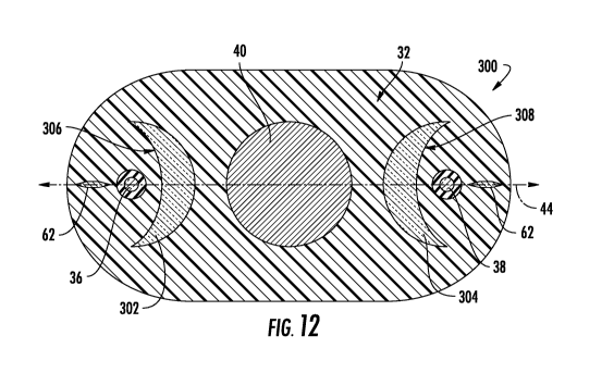
100861 Referring to FIG. 12, a strain or vibration sensing optical fiber cable
300 is shown
according to an exemplary embodiment. Cable 300 is substantially the same as
cable 30,
except for the differences discussed herein. Cable 300 includes one or more
acoustic
reflector, shown as reflectors 302 and 304, embedded in cable jacket 32. In
general,
reflectors 302 and 304 are formed from a material that has an acoustic
impedance greater
than the acoustic impedance of the material of cable jacket 32. Reflector 302
has a vibration-
reflecting surface, shown as concave surface 306, and reflector 304 has a
vibration-reflecting
surface, shown as concave surface 308. As shown in FIG. 12, reflectors 302 and
304 are
embedded in the material of cable jacket 32 such that the material of cable
jacket 32 is in
contact with surfaces 306 and 308, and specifically, cable jacket 32 may
surround reflectors
302 and 304 such the reflectors are completely embedded within cable jacket
32.
100871 Referring to FIG. 13, a detailed view of reflector 304 is shown
illustrating vibrational
reflection provided by reflector 304. It should be understood that reflector
302 functions the
same as reflector 304. Vibrational waves, shown schematically as horizontal
vibrations 310,
are transmitted through a portion of outer surface 34 into cable jacket 32.
The horizontal
vibrations 310 continue to travel through cable jacket 32 until they encounter
reflector 304.
As illustrated by Equation 1 above, a large portion of the power of vibrations
310 reflect off
of reflector 304 due to the acoustic impedance difference between the material
of reflector
304 and of the material ofjacket 32. The concave shape of surface 308 reflects
portions of
vibrations 310 (that would have otherwise missed sensing fiber 38) toward
sensing fiber 38.
[0088] As will be understood from Equation 1, the greater the acoustic
impedance difference
between the material of reflectors 302 and 304 and of cable jacket 32, the
larger the
proportion of vibrational power that is reflected back toward sensing fibers
36 and 38. In
various embodiments, the acoustic impedance of the material of reflectors 302
and 304 is at
least twice, specifically is at lease 5X and more specifically is at least 10X
of the acoustic
impedance of the material of cable jacket 32.
100891 A wide variety of materials may be used to form reflectors 302 and 304.
In some
embodiments, reflectors 302 and 304 may be formed from a high acoustic
impedance
polymer material, and in such embodiments reflectors 302 and 304 may be
coextruded with
21
CA 03065509 2019-11-28
WO 2018/222541
PCT/US2018/034672
jacket 32. In other embodiments, reflectors 302 and 304 may be separate
structures around
which jacket 32 is extruded. In exemplary embodiments, reflectors 302 and 304
may be a
metal material or a high density polymer material, and in a specific
embodiment, reflectors
302 and 304 may be formed from an aluminum Mylar material.
100901 As shown in FIG. 12, sensing fibers 36 and 38 are located along
horizontal axis 44
and are positioned adjacent opposite ends of cable jacket 32 with strength
member 40 in
between the two sensing fibers. In this arrangement, reflector 302 is located
between sensing
fiber 36 and tensile strength member 40 along horizontal axis 44, and
reflector 304 is located
between sensing fiber 38 and tensile strength member 40 along horizontal axis
44. In this
arrangement, reflecting surfaces 306 and 308 face in opposite directions from
each other
along horizontal axis 44. In the particular embodiment shown in FIG. 12,
strength element
40 is a centrally located strength element that is coaxial with the
longitudinal axis of cable
300 and is equidistant from reflectors 302 and 304 and from sensing fibers 36
and 38. In
other embodiments, two strength elements and/or additional optical fibers may
be located
along horizontal axis 44 between reflectors 302 and 304.
100911 As shown in FIG. 12, reflectors 302 and 304 are positioned and shaped
different from
other materials/layers that may be found in typical fiber optic cables. For
example, unlike
typical buffer tubes or wrapped armor layers, concave surfaces 306 and 308 of
reflectors 302
and 304 are in contact with the material of cable jacket 32. In addition,
concave surfaces 306
and 308 of reflectors 302 and 304 define arc angles less than 360 degrees
(i.e., they do not
circumscribe fibers 36 and 38), specifically less than 270 degrees, and more
specifically less
than 180 degrees.
100921 In specific embodiments, cable 300 has a width dimension (in the
horizontal direction
in the orientation of FIG. 12) between 3 mm and 4 mm, specifically of 3.5 mm,
and a height
dimension (in the vertical direction in the orientation of FIG. 12) between 1
mm and 2 mm,
specifically of 1.8 mm. In such embodiments, strength member 40 has an outer
diameter of 1
mm. In such embodiments, the height of reflectors 302 and 304 is between 0.5
mm and 2
mm and specifically is 1 mm. In such embodiments, sensing fibers 36 and 38 are
located a
distance of between .1 mm and .5 mm, and specifically 0.25 mm from surfaces
306 and 308,
respectively, along horizontal axis 44.
100931 Referring to FIG. 14, a strain or vibration sensing optical fiber cable
320 is shown
according to an exemplary embodiment. Cable 320 is substantially the same as
cable 300,
22
CA 03065509 2019-11-28
WO 2018/222541
PCT/US2018/034672
except for the differences discussed herein. Cable 320 includes a single
sensing optical fiber
36 generally located along the central longitudinal axis of cable 320.
[0094] Cable 320 includes a first pair of acoustic reflectors, 322 and 324,
and a second pair
of acoustic reflectors, 326 and 328. Like the reflectors of cable 300,
acoustic reflectors 322,
324, 326 and 328 are formed from a material having an acoustic impedance
greater than the
acoustic impedance of the material of cable jacket 32 and each has a concave
vibration
reflecting surface 329, 330, 332, 334, respectively.
[0095] The reflecting surfaces 329, 330, 332, 334, are shaped and positioned
such that
incoming vibration waves, shown schematically at 310, are reflected off of
reflecting surfaces
329, 330, 332, 334 and directed toward sensing fiber 36. Specifically, concave
reflecting
surfaces 329, 330, 332, 334 each face sensing fiber 36 and are concave
relative to sensing
fiber 36. In other embodiments, acoustic reflectors 322, 324, 326 and 328 may
have a variety
of other shapes including bead shaped or rectangular shapes.
[0096] In the embodiment shown in FIG. 14, reflectors 322, 324, 326 and 328
are coupled to
strength elements 40 and 42. In specific embodiments, reflectors 322, 324, 326
and 328 may
be integral (e.g., coextruded, molded, etc.) with strength members 40, and in
other
embodiments, reflectors 322, 324, 326 and 328 may separate components embedded
in jacket
32 adjacent to and contacting strength members 40 and 42. In some embodiments,
strength
members 40 and 42 and reflectors 322, 324, 326 and 328 are all formed from the
same high
acoustic impedance material as each other, and in another embodiment,
reflectors 322, 324,
326 and 328 are formed from a material that is different from and has a higher
acoustic
impedance than the material of strength members 40 and 42.
[0097] As shown, each of strength elements 40 and 42 have a convex outer
surface 336, and
reflectors 322, 324, 326 and 328 are each coupled to the convex outer surface
336 of one of
strength members 40 and 42. In such embodiments, reflectors 322, 324, 326 and
328 may
provide both acoustic reflecting and additional strength to cable 320. In the
particular
arrangement shown, reflectors 322 and 324 are located on opposite sides of
horizontal axis 44
from each other, and specifically are spaced 180 degrees from each other
around strength
element 40. Similarly, reflectors 326 and 328 are located on opposite sides of
horizontal axis
44 from each other, and specifically are spaced 180 degrees from each other
around strength
element 42.
[0098] Referring to FIG. 15, a strain or vibration sensing optical fiber cable
340 is shown
according to an exemplary embodiment. Cable 340 is substantially the same as
cable 320,
23
CA 03065509 2019-11-28
WO 2018/222541
PCT/US2018/034672
except for the differences discussed herein. Cable 340 has a cylindrically
shaped cable jacket
342 that defmes a cylindrical outer surface 344. Cable 340 has a centrally
located strength
member 40.
100991 Cable 340 includes a plurality of acoustic reflectors, shown as
reflectors 346, 348, 350
and 352 coupled to and surrounding strength member 40. Reflectors 346, 348,
350 and 352
may be integral (e.g., coextruded, molded, etc.) with strength members 40, and
in other
embodiments, reflectors 346, 348, 350 and 352 may separate components embedded
in jacket
342 adjacent to strength member 40. In some embodiments, strength member 40
and
reflectors 346, 348, 350 and 352 are all formed from the same high acoustic
impedance
material as each other, and in another embodiment, reflectors 346, 348, 350
and 352 are
formed from a material that is different from and has a higher acoustic
impedance than the
material of strength member 40.
1001001 As shown in FIG. 15, cable 340 includes sensing fibers 36 and 38
spaced from each
other along horizontal axis 44 and a pair of additional sensing fibers 356 and
358 that are
spaced from each other along the vertical axis of cable 340. Reflectors 346,
348, 350 and 352
have concave acoustic reflecting surfaces 360, 362, 364 and 366. Reflecting
surfaces 360,
362, 364 and 366 each face and are concave relative to an associated sensing
fiber such that
incoming vibrations are reflected toward the associated sensing fiber.
1001011 In this arrangement, cable 340 includes four sensing fibers each
spaced
approximately 90 degrees from each other. In this arrangement cable 340 is
radially
symmetric. In this arrangement, cable 340 is configured to detect vibrations
received from
360 degrees around the perimeter of cable 340 with one sensing fiber in each
quadrant of the
cable, while maintaining a small, compact form factor.
1001021 In a specific embodiment, cable 340 has an outer diameter between 1.5
mm and 3
mm, and specifically of 2 mm. In such embodiments, sensing fibers 36, 38, 356
and 358
have outer diameters of 250 microns. In such embodiments, the radial distance
from the
center point of strength member 40 to the center point of each sensing fibers
36, 38, 356 and
358 is between 0.2 mm and 1.3 mm and more specifically is 0.6 mm. In a
specific
embodiment, strength element 40 is a steel strength element having an outer
diameter of 0.7
mm. Table 2 below shows the relation between the fiber offset positioning,
bend radius and
fiber strain for different arrangements of cable 340.
24
CA 03065509 2019-11-28
WO 2018/222541 PCT/US2018/034672
Table 2
iMAL AddIt tondl Ft be, Stra.n Mgrcgote-rOffwt 03,01:mq+Offjp)
Send Rad}USW *A *5 05 al
EMENEEMENEIN = 'z
IIEEMEIMMIEN
7 0.24% magnmegg __=
CE121111111=111 0.50%
ilIZEKTEENEETE ,8/.
14 wool ram 0 lc; / -,r?
rEzmumn 0.2' O.354
EMI ECM EMI EMI
1001031 Referring to FIG. 16, a strain or vibration sensing optical fiber
cable 380 is shown
according to an exemplary embodiment. Cable 380 is substantially the same as
cable 30,
except for the differences discussed herein. Cable 380 has a cable jacket 382,
and a single
optical sensing fiber 36. In this embodiment, sensing fiber 36 is a tight-
buffered optical fiber
having a tight buffer layer 384 coupled to and surrounding sensing fiber 36.
1001041 Cable 380 includes an outer surface 388 that surrounds sensing fiber
36. In the
particular embodiment shown, cable jacket 382 defmes a part or all of outer
surface 388. In
contrast to typical cable arrangements, outer surface 388 includes a concave
portion 390 that
is concave relative to the exterior of cable 380.
1001051 In general, concave surface 390 is shaped and positioned relative to
sensing fiber 36
such that incoming vibrations, represented schematically at 310, are refracted
as the incoming
vibrations are transmitted into cable jacket 382. As shown schematically in
FIG. 16, as
vibrations 310 enter cable jacket 382 they are refracted to a new direction of
travel or path
392. Concave surface 390 is shaped and/or positioned relative to sensing fiber
36 in a
manner that increases the proportion of vibrations 310 that are directed
toward sensing fiber
36. In particular, concave surface 390 is positioned such that is symmetric
about an axis,
shown as horizontal axis 44 that intersects sensing fiber 36.
1001061 As will be understood, the appropriate radius of curvature for the
concave surface
390 will be determined based on the speed of sound in the jacket material
used. The exact
shape of the cable transition between region of planar only sensitivity to
combined
planar/reflected energy can be optimized depending on the strength of the
planar wave vs.
reflected wave. It is believed that the transition would be a function of
depth of bedrock and
distance from the vibration producing event to determine the ratio of planar
wave energy to
reflected wave energy.
1001071 Referring to FIGS. 17A, 17B and 18, in various embodiments, the
radiuses of cable
jackets (e.g., the radius of cylindrical cable jackets, the radiuses at the
comers of oblong cable
CA 03065509 2019-11-28
WO 2018/222541
PCT/US2018/034672
jackets, etc.) may be selected in relation to sensing fiber size and
positioning to increase the
proportion of vibrational energy directed toward the sensing fiber via
refraction as the
vibrations are transmitted into the cable jacket material. Referring to FIG.
17A and FIG.
17B, a model that takes into account the radius of curvature and dimensions of
the cable
jacket and of the fiber and how they apply to calculate a maximum potential
angle for direct
energy transfer are shown.
1001081 Based on this model, a limiting angle is determined based on the
potential angular
profile and the critical angle for reflectance that increase the proportion of
vibrational energy
directed toward the sensing fiber via refraction. Since the speed of sound in
the cable jacket
is higher than the surrounding soil, FIG. 17B shows that acoustic waves will
be refracted out
away from the center of the cable. Thus, to counter the tendency to refract
acoustic waves
away from the sensing fiber at the center of the cable, the curvature of the
cable can be
selected to increase the proportion of acoustic waves refracted toward the
sensing fiber.
1001091 Referring to FIG. 17A and 17B, the ability to transfer increased or
maximum
acoustic energy to a sensing fiber, such as fibers 36 and 38, from the soil is
a function of both
the cable materials and component dimensions. Assuming the sensing fiber is
centered inside
the radius of curvature of the outer surface of the jacket, the component
dimensions for the
sensing fiber and cable radius determine the potential angle for direct energy
transfer (20a)
from the acoustic wave (see FIG. 17A). The critical angle for refractive
energy transfer
(Snell's Law) Oci is a function of material properties between the soil (or
other environment)
and the cable jacket. A limiting angle for energy transfer is determined by
the limiting
(smallest) value between the dimensional cable properties and the critical
angle. This is
observed in FIG. 17B where the speed of sound for soil is assumed to be 250
m/s. For this
case, transfer of vibrations from soil to a polyethylene cable jacket, is
limited to a maximum
angular surface for energy transfer of 14.7 degrees due to the critical angle
between the two
materials. Above a cable radius of about 1 mm for 250 micron optical fiber and
a cable
radius of about 3.5 mm for 900 micron tight buffered optical fiber, the
maximum angular
surface for energy transfer is limited by the potential angle 20cr.
1001101 Incorporating a material with a lower speed of sound will increase the
effective
region of acoustic energy transfer (see cable 200 in FIG. 9). For example, Dow
Silastic
Rubber (shown in Table 1 above) is limited to a maximum angular surface for
energy transfer
of 28.4 degrees (significantly greater than polyethylene). To obtain the
benefit for 250
micron fiber, the cable radius should be below 1 mm, preferably at ¨ 0.5 mm.
To obtain the
26
CA 03065509 2019-11-28
WO 2018/222541
PCT/US2018/034672
benefit for 900 micron tight buffered fiber, the cable radius should be below
3.5 mm,
preferably at or below ¨ 1.8 mm.
1001111 Thus, based on this analysis, relative sizing/positioning for the
cable jacket radius
and fiber diameter and positioning can be determined to increase transfer of
vibrational
energy to sensing fibers. In an exemplary embodiment, FIG. 18 shows a
vibration sensing
cable 400 that utilizes these concepts. Vibration sensing cable 400 is
substantially the same
as cable 200 except as discussed herein. Vibration sensing cable 400 is
arranged based on the
modeling shown in FIGS. 17A and 17B to increase refraction-based vibration
direction to
sensing fibers 36 and 38.
1001121 As shown in FIG. 18, sensing fibers 36 and 38 each include a tight
buffered layer
402. In this embodiment where sensing fibers 36 and 38 are tight buffered
optical fibers, the
tight buffer layer 402 defines the outer fiber radius shown as R3. In
embodiments, where
sensing fibers 36 and 38 are not surrounded by tight buffer layer 402. R2 is
measured to the
outer surface of coating layer 52 shown for example in FIG. 2. In addition,
the end sections
of cable jacket 200 (adjacent to and surrounding sensing fibers 36 and 38) are
defined by a
radius shown as R2.
1001131 As discussed above regarding FIGS. 17A and 17B, R2 may be selected to
improve
the proportion of vibrational energy directed toward sensing fibers 36 and 38
via refraction.
Specifically, Applicant has determined that by shaping cable jacket 200 such
that R2 is less
than 8 times R3, vibrational energy transfer to sensing fibers 36 and 38 can
be increased. In
specific embodiments, R2 is less than eight times R3. In even more specific
embodiments,
R3 is 450 microns and R2 is less than 3.6 mm and more specifically is less
than or equal to
1.8 mm. In another specific embodiment, R3 is 125 microns and R2 is less than
1 mm and
more specifically is less than or equal to 0.5 mm.
1001141 In various embodiments, a method of detecting vibrations in an
environment
utilizing a vibration sensing optical cable is provided. In various
embodiments, the method
discussed herein may utilize any combination of the acoustic sensing
enhancement designs of
any of the cable embodiments discussed herein. In specific embodiments, the
method
includes the step of placing a vibration sensing cable in the environment
(e.g., ground 12). In
such embodiments, the vibration sensing cable includes a cable jacket defining
an outer
surface of the vibration sensing cable, and a vibration sensing optical fiber
embedded within
the cable jacket. The cable is positioned such that the outer surface of the
vibration sensing
cable is in contact with the environment forming an interface between the
outer surface and
27
CA 03065509 2019-11-28
WO 2018/222541
PCT/US2018/034672
the environment. The cable utilized in this method may be any of the cable
embodiments
discussed herein.
1001151 The method includes transmitting vibrational waves within the
environment into the
cable jacket through the interface. As will be understood, the vibrational
waves have a
direction of travel within the environment. The method includes altering the
direction of the
vibrational waves from the direction of travel within the environment to a
path of travel
within the cable jacket that intersects the vibrational-sensing optical fiber.
1001161 In one embodiment, the step of altering the direction of the
vibrational waves is
accomplished with an acoustic reflector (such as the reflectors of cables 300,
320 and/340
discussed above) positioned within the cable jacket that reflects vibrational
waves traveling
within the cable jacket toward the vibration sensing optical fiber. In another
embodiment, the
step of altering the direction of the vibrational waves is accomplished with a
concave surface
(e.g., the concave surface of cable 380 discussed above) located along the
outer surface of the
cable jacket. The concave surface is positioned relative to the vibrational
waves such that
refraction of the vibrational waves incident at the concave surface directs
the vibrational
waves traveling within the cable jacket toward the vibration sensing optical
fiber.
1001171 In yet other embodiments, the direction of vibrational wave travel is
altered
utilizing refraction by selecting the radius of curvature of the cable jacket
based on the size
and positioning of the sensing fiber. In one such embodiment, the cable used
in the method is
cable 400 as discussed above. In such embodiments, the direction of
vibrational waves is
altered through refraction by fonning the cable jacket such that R2 is less
than 8 times R3. In
a specific embodiment, the direction of vibrational waves is altered through
refraction by
forming the cable jacket such that R2 is less than 3.6 mm when R3 is 450
microns and more
specifically R2 is less than or equal to 1.8 mm when R3 is 450 microns. In a
specific
embodiment, the direction of vibrational waves is altered through refraction
by forming the
cable jacket such that R2 is less than 1 mm when R3 is 125 microns and more
specifically R2
is less than or equal to 0.5 mm when R3 is 125 microns.
1001181 The optical fibers discussed herein include optical fibers that may be
flexible,
transparent optical fibers made of glass or plastic. The fibers may function
as a waveguide to
transmit light between the two ends of the optical fiber. Optical fibers may
include a
transparent core surrounded by a transparent cladding material with a lower
index of
refraction. Light may be kept in the core by total internal reflection. Glass
optical fibers may
comprise silica, but some other materials such as fluorozirconate,
fluoroaluminate, and
28
CA 03065509 2019-11-28
WO 2018/222541
PCT/US2018/034672
chalcogenide glasses, as well as crystalline materials, such as sapphire, may
be used. The
light may be guided down the core of the optical fibers by an optical cladding
with a lower
refractive index that traps light in the core through total internal
reflection. The cladding may
be coated by a buffer and/or another coating(s) that protects it from moisture
and/or physical
damage. These coatings may be UV-cured urethane acrylate composite materials
applied to
the outside of the optical fiber during the drawing process. The coatings may
protect the
strands of glass fiber. The optical transmission elements discussed herein can
include a wide
variety of optical fibers including multi-mode fibers, single mode fibers,
bend
insensitive/resistant fibers, etc. In other embodiments, the optical cables
discussed herein
may include multi-core optical fibers, and in this embodiment, each optical
transmission
element may be a single, integral optical structure having multiple optical
transmission
elements (e.g., multiple optical cores surrounded by cladding).
1001191 In accordance with yet other aspects of the present disclosure,
vibration sensing
cables may include a cable jacket defining an outer surface having specific
contoured patterns
formed or provided on the outer surfaces of the cable to create an
interference fit with the
ground environment when the cable is installed into the ground environment.
For example,
the contoured pattern may include a pattern of ridges and valleys mechanically
formed into
the outer jacket wherein aspects of the ground environment may fill in or, for
example, in the
case of concrete or asphalt, flow into the contoured pattern to create
increased friction when
the ground environment settles or the concrete or asphalt cures. The increased
friction in
combination with aspects of a pliable polyethylene jacket and the strength of
the strain
sensing cables disclosed herein can assist in the survivability rate of cables
when cracks occur
in the ground environment, such as in a concrete bridge section or roadway. In
many cases,
the displacement that results from crack formation occurs instantaneously. The
contoured
patterns may enable the cable jacket to provide a degree of yield and absorb
the infinite
forces created by instantaneous displacement from zero to crack width so that
the optical
fibers and cable survive.
1001201 Unless otherwise expressly stated, it is in no way intended that any
method set forth
herein be construed as requiring that its steps be performed in a specific
order. Accordingly,
where a method claim does not actually recite an order to be followed by its
steps or it is not
otherwise specifically stated in the claims or descriptions that the steps are
to be limited to a
specific order, it is in no way intended that any particular order be
inferred. In addition, as
29
CA 03065509 2019-11-28
WO 2018/222541
PCT/US2018/034672
used herein, the article "a" is intended to include one or more than one
component or element,
and is not intended to be construed as meaning only one.
1001211 It will be apparent to those skilled in the art that various
modifications and
variations can be made without departing from the spirit or scope of the
disclosed
embodiments. Since modifications, combinations, sub-combinations and
variations of the
disclosed embodiments incorporating the spirit and substance of the
embodiments may occur
to persons skilled in the art, the disclosed embodiments should be construed
to include
everything within the scope of the appended claims and their equivalents.