Note: Descriptions are shown in the official language in which they were submitted.
IMPLOSION SHIELD APPARATUS AND METHOD
CROSS-REFERENCE TO RELATED APPLICATIONS
100011 None.
STA1LMENT REGARDING FEDERALLY SPONSORED RESEARCH OR
DEVELOPMENT
[0002] None.
FIELD OF THE INVENTION
[0003] This invention relates to an apparatus for shielding an implosion
device used
on a powerline, a method of installing an apparatus for shielding an implosion
device on
a powerline, and a method and apparatus for protecting adjacent apparatus such
as
insulators, tools, hoists, grips and slings.
BACKGROUND OF THE INVENTION
[0004] In the process of electrically joining two free ends of separate
electrical
powerline conductors to create a single, continuous electrically conductive
joint, a
mechanical connection is typically used to join the two free ends and maintain
electrical
integrity and requisite ampacity in the conductor. To achieve the requisite
mechanical
connection to provide an electrically sufficient electrical connection, an
implosion device
may be used to form the joint and mechanical connection with the two free ends
of the
separate conductors. While implosion devices have typically been adequate in
achieving
the desired mechanical connection properties to safely join the two free ends
of two
conductors, while achieving the desired electrical connection of the two free
ends, such
implosion devices are not without limitations, and room for improvement
exists. What is
desired is an apparatus and method of using an apparatus to reduce audible
implosion
noise and contain blast debris while maintaining the desired mechanical and
electrical
connection of two free ends of two separate electrical conductors.
BRIEF SUMMARY OF THE DISCLOSURE
The disclosure may include an implosion device such as an implosion sleeve or
implosion dead-end sleeve and a protective implosion cover or shield
surrounding the
12073261.1 1
CA 3065707 2019-12-20
implosion device. An implosion device, an implosion protective cover or shield
that at
least partially surrounds the implosion sleeve, and a frame that supports the
implosion
cover. The frame may be located at least partially above and below or around
the
implosion device. Also, at least a part of the frame may be approximately
perpendicular
to the implosion device. The implosion protective cover or shield may act as a
blast,
shock wave and sound attenuating protective barrier. The disclosure may
include a
method of installing an implosion device on a powerline (e.g. two separate
loose ends of
different abutting conductors or terminating a conductor end to hold tension),
and
installing an implosion protective cover or shield around the implosion
device.
BRIEF DESCRIPTION OF THE DRAWINGS
[0005] A more complete understanding of the present disclosure and
benefits thereof
may be acquired by referring to the follow description taken in conjunction
with the
accompanying drawings in which:
[0006] Figure 1 is a perspective view of a powerline with an implosion
cover placed
over and around an implosion sleeve, in accordance with the present
disclosure;
[0007] Figure 2 is a side view of an implosion sleeve in accordance with
the present
disclosure;
[00081 Figure 3 is a perspective view of an implosion cover enveloping
an implosion
sleeve in accordance with the present disclosure;
[0009] Figure 4 is a perspective view of an implosion cover enveloping
an implosion
sleeve in accordance with the present disclosure;
[0010] Figure 5 is a perspective view of an implosion cover surrounding
an implosion
sleeve in accordance with the present disclosure;
[0011] Figure 6 is an end view of an implosion cover rolled or wrapped
around an
implosion sleeve in accordance with the present disclosure;
100121 Figure 7 is a top view of Figure 6 of an implosion cover rolled
or wrapped
around an implosion sleeve in accordance with the present disclosure;
[0013] Figure 8 is a top view of material of an implosion cover in
accordance with
the present disclosure;
2
CA 3065707 2019-12-20
[0014] Figure 9 is a perspective view of an implosion sleeve with an
implosion cover
draped over the implosion shield;
[0015] Figure 10 is a perspective view of an implosion sleeve with an
implosion
cover surrounding an exterior of the implosion sleeve;
100161 Figure 11 is a perspective view of an implosion sleeve with an
implosion
cover surrounding an exterior of the implosion sleeve;
[0017] Figure 12 is a perspective view of an implosion dead-end sleeve
joining an
electrical conductor to a dead-end tower; and
[0018] Figure 13 is an enlarged view of the implosion dead-end sleeve
joining an
electrical conductor to a dead-end tower depicted in Figure 12.
DETAILED DESCRIPTION
[0019] Turning now to a detailed description of the present teachings
with reference
to Figures 1-8, features and concepts also may be manifested in other
arrangements and
so the scope of the teachings is not limited to the embodiments described or
depicted in
Figures 1-8. The following examples of certain embodiments of the teachings
are
provided. Each example is provided by way of explanation of the teachings, one
of many
examples of the teachings, and the following examples should not be read to
limit, or
define, the scope of the teachings.
[0020] Figure 1 depicts an example of an outdoor electrical powerline 10
with an
electrical conductor 16 attached to electrical powerline towers 12, 14.
Electrical
conductor 16 is attached to powerline tower 12 using an insulator 18, and to
powerline
tower 14 using an insulator 20. Due to extreme lengths of electrical
conductors used in
delivering electricity, electrical conductor 16 may be separate pieces joined
together to
form electrical conductor 16. As an example, electrical conductor 16 may be an
electrical
conductor 22 and electrical conductor 24 joined together by an implosion
sleeve 26.
Implosion sleeve 26 may be used to join conductor 22 and conductor 24 when a
lineman
or person residing within bucket 13 of bucket truck 11 installs implosion
sleeve 26 into
place over each loose end of conductor 22 and conductor 24. Figure 1 also
depicts an
implosion cover 34 in place over and around implosion sleeve 26, in accordance
with
3
CA 3065707 2019-12-20
teachings of the present disclosure. Implosion cover 34 may be manufactured
from an
explosion or blast reduction type of material, as will be explained herein.
[0021] Figure 2 depicts a larger view of implosion sleeve 26 whose
subcomponents
may be an aluminum tube 28 that is surrounded or wrapped by an explosive
product 30.
Explosive wrap product 30 may be detonation cord that is wrapped for
approximately the
entire length of aluminum tube 28. An additional layer of explosive wrap
product 32
(also detonation cord) may be wrapped around layer of explosive product 30 in
a
centralized fashion as depicted in Figure 2 to ensure an effective implosion
to join
electrical conductor 22, electrical conductor 24 and implosion sleeve 26 to
form a
properly welded, melted and compressed joint between electrical conductor 22,
electrical
conductor 24 and aluminum tube 28 of implosion sleeve 26. Alternatively,
explosive
wrap product 32 may additionally act as a protective wrap to keep explosive
product 30
in place in the central position of implosion sleeve 26.
[00221 Figure 3 depicts implosion sleeve 26 within an implosion cover
34. Implosion
cover 34 may be made of a ballistic fabric. Ballistic fabric is a fabric that
is capable of
absorbing and deflecting explosions and fragmentation depending upon its
arrangement
relative to an explosion. Energy of any projectile that reaches the ballistic
fabric is
absorbed by the ballistic fabric upon impact with the ballistic fabric. To be
effective,
ballistic fabric is woven of yarn that stretches at relatively low strain
rates before
reaching its yield stress. An explosion causes a longitudinal stress to be
transmitted
through a yarn pair, which allows the whole or entire yarn in a ballistic
fabric to absorb
the loading caused by an explosion. In other words, stress and strain loading
at one
location in the fabric is absorbed by the entire fabric structure, or at least
more of the
fabric structure than the local impact point. Relative to other fabrics,
ballistic fabric
absorbs greater energy as work is performed on more of the fabric surrounding
the impact
zone. The ballistic fabric of the present disclosure and teachings may be an
auxetic
structure or material. An auxetic structure or material is one that has a
negative Poisson's
ratio, which means that it is a structure or material that increases in
dimension (e.g.
becomes thicker) when a tensile force is applied perpendicular to that
increase in
dimension. The internal structure of the material is designed or exists in
such a way that
deformation increases perpendicular to a uniaxial load. A ballistic fabric in
accordance
4
CA 3065707 2019-12-20
with the present teachings and disclosure may be constructed of parallel yarns
with
independent wrap fibers weaved around the yarn. In one example, when a
projectile from
an explosion or from an imploding device, strikes the ballistic fabric, the
yams are loaded
by stretching and absorb any stress in the yams. The wrap fibers woven around
the yarn
under strain also absorb some of the strain energy, as the yarn is in tension
and expands
or grows into the wrap fibers. Thus, strain energy transferred into the wrap
fiber weaves
is enhanced, and thus strain energy transferred into the entirety of a piece
of ballistic fiber
is enhanced. Although a ballistic fabric has been described that can be used
in
accordance with the present teachings, a ballistic fabric that may be
purchased and used
as any of the implosion covers depicted and discussed in accordance with the
present
teachings may be sourced from Meridian.us in Mobile, Alabama, USA.
[0023] Continuing with Figure 3, implosion cover 34 may be a single
rectangular
piece of ballistic fabric that is folded once around implosion sleeve 26.
Thus, edge or
fold 36 is where implosion cover 34 would double-back or change direction so
that edge
38 could exist to be the mating location of loose ends of implosion cover 34.
Thus, to
transform edge 38 from an open end with two, unconnected pieces, to a closed
end, a
fastener 40, or series of fasteners, could be used along edge 38 to secure
implosion cover
34 over implosion sleeve 26. Thus, as depicted in Figure 3, implosion cover 36
has a first
side 42 and a second side 44 that are on opposite sides of implosion sleeve
26. Fastener
40 may be a rivet, screw with nut, stitching, or other fastener to secure edge
38 of
implosion cover 34. While edge 36 and edge 38 are closed edges, adjacent sides
of
implosion cover 36 are open as exhibited by opening 46 and opening 48, such
that the
area and volume between opening 46 and opening 48 is a pass-through to permit
air to
freely pass, such as in the event of activation of implosion sleeve 26, which
will be
explained later.
[0024] Figure 4 depicts an embodiment similar to Figure 3 except that
instead of a
single piece of an implosion cover with a fold at edge 36 (Figure 3), Figure 4
depicts two
pieces of ballistic fabric joined together to form a cover. First ballistic
cover 50 and
second ballistic cover 52 may be located on opposite sides of implosion sleeve
26 with a
select fastener 54 used to join First ballistic cover 50 and second ballistic
cover 52 at
edge 56 and edge 58. Fastener 54 may be a rivet, bolt and nut, stitching or
other secure
CA 3065707 2019-12-20
fastener. Similar to the construction of Figure 3, edges or sides adjacent to
edge 56 and
edge 58 may be open to permit the free flow of gases during implosion of
implosion
sleeve 26. Air and pressure waves may escape through open end 60 and open end
62 at
the same time any debris, pressure and shock waves are contained along edge 56
and
edge 58.
[0025]
Figure 5 depicts another embodiment in which two separate pieces of ballistic
fabric, each acting as an implosion cover, such as implosion cover 64 and
implosion
cover 66, which are located on opposite sides of implosion sleeve 26. To
securely place
implosion cover 64 and implosion cover 66 around implosion sleeve 26, multiple
installations of a fastener 68 may be used around the entire edge or periphery
of
implosion cover 64 and implosion cover 66. Fastener 68 may be a rivet, bolt
and nut,
stitching, or other suitable fastener able to withstand activation of
implosion sleeve 26
without failing. When implosion sleeve 26 is activated, implosion cover 64 and
implosion cover 66 prevent debris from passing beyond implosion cover 64 and
implosion cover 66. Tmplosion cover 64 and implosion cover 66 also lessen any
sound
waves and pressure shock waves caused by activation of implosion sleeve 26.
Thus, the
measured air pressure on a side of implosion cover 64 or implosion cover 66
that is
opposite to the side next to implosion sleeve 26, will be less than the
measured air
pressure next to implosion sleeve 26 during activation of implosion sleeve 26.
Thus,
implosion cover 64 and implosion cover 66 effectively reduce air pressure
during
implosion of implosion sleeve 26. Regardless of configuration, when an
implosion cover
of the present teachings is located between a person and a detonating
implosion sleeve
26, the sound, pressure shock wave, and air pressure experienced by a
bystander are all
less than if no implosion cover were in place between implosion sleeve 26 and
the
bystander. Sound and shock waves are an annoyance to people and animals in
proximity
to detonation of implosion sleeve 26. Although implosion cover 64 and
implosion cover
66 lessen any sound waves and pressure shock waves caused by activation of
implosion
sleeve 26, increased air pressure between implosion cover 64 and implosion
cover 66 due
to detonation can escape between any two fasteners 68 about the periphery or
edges of
implosion cover 64 and implosion cover 66 via paths 70.
6
CA 3065707 2019-12-20
[0026] Figure 6 depicts another embodiment of the disclosure in which a
single piece
of ballistic fabric, which may be rectangular, can be secured, fixed or
otherwise placed
around implosion sleeve 26 by wrapping or rolling ballistic fabric as an
implosion cover
72. Figure 6 is an end view (along a powerline) of implosion sleeve 26
depicting
implosion cover 72 in its wrapped-around or rolled installation position
around implosion
sleeve 26, which offers at least one advantage in that multiple layers can
provide
additional blast, debris, sound wave, and shock wave protection to the area
outside or
beyond the implosion cover 72, during an implosion of implosion sleeve 26.
Implosion
cover 72 has an end 74.
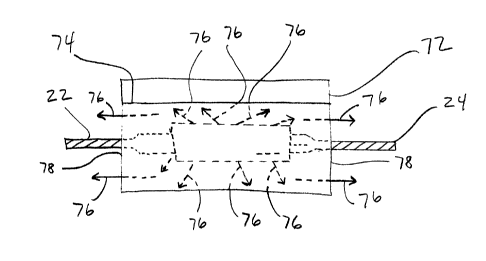
[0027] Figure 7 is a side view of Figure 6. Figure 7 depicts implosion
sleeve 26 with
a single piece of ballistic fabric, which may be rectangular, and secured or
otherwise
placed around implosion sleeve 26 by wrapping or rolling the ballistic fabric
to become
an implosion cover 72. Explosion debris, accelerated air, shock waves, and
sound waves
may travel, as a result of detonating and therefore imploding implosion sleeve
26, in
accordance with paths 76 which have an exist out of implosion cover 72 at ends
78 of
implosion cover 72. Thus, debris falling to the ground may be lessened, sound
may be
attenuated, and shock waves reduced when employing any implosion cover in
accordance
with the teachings of the present disclosure.
[0028] Figure 8 depicts how the material of implosion cover 34 could be
woven or
configured if an implosion cover material for implosion cover 34 is not
sourced
commercially. Core fibers 80 and wrap fibers 82 may be configured as depicted
in
Figure 8. That is, a single wrap fiber 82 may simply wrap or wind around a
single core
fiber 80. Parallel core fibers 80 may be joined or woven together with
connecting fibers
84, which as depicted, alternate in crossing above two core fibers 80, and
then crossing
under the next two core fibers 80 and may continue in that fashion for the
entire size of
implosion cover 34. The material used as an implosion cover may meet the
latest
revision, or any revision, of U.S. military specification MIL-STD-2105.
[0029] A method of utilizing an implosion cover 34 on a powerline 10 may
include
installing an implosion sleeve 26 on an electrical conductor 22 and an
electrical
conductor 24 (i.e. a powerline), such as by using a bucket truck 11 as
depicted in Figure
I, and then wrapping implosion cover 72 around implosion sleeve 26 as depicted
in
7
CA 3065707 2019-12-20
Figure 6. The method of wrapping or coiling implosion cover 72 around
implosion '
sleeve 26 may further include forming multiple layers of implosion cover 72
around
implosion sleeve 26. The method may include using multiple, completely
separate pieces
of implosion material that each are, and act as, an implosion cover. Such
separate pieces
may be square or rectangular sections that form an implosion cover when joined
or
fastened together, such as implosion cover 34 explained in connection with
Figures 3, 4
and 5. The method may include securing the implosion cover 72 using fasteners
such as
rivets, bolts, or stitching using plastic, nylon, or other natural or
synthetic materials,
including KEVLAR brand material. The method of utilizing an implosion cover
may
further include detonating the implosion sleeve, and attenuating shock waves
and sound
waves with the implosion cover.
[0030] Figure 9 depicts a perspective view of an implosion sleeve 26
with an
implosion cover 86 draped over and draped around implosion sleeve 26. In the
embodiment depicted in Figure 9, implosion cover 86 is not supported by any
type of
frame, but is merely draped or placed around implosion sleeve 26 such that an
inside
surface 88 of implosion cover 86 contacts a portion of implosion sleeve 26.
More
specifically, as an example, when implosion cover 86 is placed around
implosion sleeve
26, a top inside fold edge 90 may contact an outside surface of implosion
sleeve 26.
With this arrangement, shock waves, noise waves, and any debris from
detonating
implosion sleeve 26 may be attenuated, lessened, or contained due to placement
of
implosion cover 86.
[0031] Figure 10 depicts a perspective view of an implosion sleeve 26
with an
implosion cover 92 surrounding an exterior of the implosion sleeve 26. In the
embodiment depicted in Figure 10, implosion cover 92 may be supported by a
frame,
which may employ a top bar 94, and a first lower bar 96, and a second lower
bar 98. In
the embodiment depicted in Figure 10, implosion cover 100 and implosion cover
102,
may be two separate pieces of auxetic ballistic blast material, the same or
similar to that
explained in this disclosure, or the implosion cover instead may be a single
piece of a
auxetic ballistic blast material. Top bar 94 may support implosion cover 100
and
implosion cover 102 if it is two pieces, or if it is one piece. In either
configuration, a first
top clamp 104 and a second top clamp 106 may affix implosion cover 100 and
implosion
8
CA 3065707 2019-12-20
cover 102 to hold them in place at and to top bar 94. First lower bar 96 and
second lower
98 may respectively secure implosion cover 100 and implosion cover 102 at
their ends
opposite to top bar 94. Top bar 94 may be supported using a first top bar
support 108 and
a second top bar support 110, which each may span between top bar 94 and
conductor 22
and conductor 24, respectively. First adjustment device 112 may be used to
extend and
retract first top bar support, and second adjustment device 114 may be used to
extend and
retract second top bar support 110. As examples, first top bar support 108 may
secure to
conductor 22 with clamp 124, and second top bar support 110 may secure to
conductor
24 with clamp 126. First lower bar 96 and second lower bar 98 may be spaced
apart and
held in place using a first lower spacer bar 116 and a second lower spacer bar
118. First
lower spacer bar 116 and second lower space bar 118 each may be adjusted to
increase or
decrease the space between first lower bar 96 and second lower bar 98 using
adjustment
device 120 and adjustment device 122, respectively, which may permit first
lower spacer
bar 116 and second lower space bar 118 telescope, or otherwise account for
spacing
changes. With this arrangement, shock waves, noise waves, and any debris from
detonating implosion sleeve 26 may be attenuated, lessened, or contained due
to
placement of implosion cover 100 and implosion cover 102, if two covers are
utilized, or
alternatively if one continuous cover is utilized.
[00321
Figure 11 depicts another embodiment in a perspective view of an implosion
sleeve 26 with an implosion cover 100 and implosion cover 102 surrounding an
exterior
of implosion sleeve 26. In the embodiment of Figure 11, an alternative frame
arrangement is depicted when compared to Figure 10. More specifically, top bar
94 and
its connection and spacing from conductor 22 and conductor 24, are secured
using first
top bar support 108 and second top bar support 110, with each being adjustable
using first
adjustment device 112 and second adjustment device 114, respectively. As
examples,
first top bar support 108 may secure to conductor 22 with clamp 124, and
second top bar
support 110 may secure to conductor 24 with clamp 126. First top clamp 104 and
second
top clamp 106 may be used to secure implosion cover 100 and implosion cover
102 to top
bar 94. Implosion cover 100 may be supported by a frame, which may be a first
bar 128
and a second bar 130, while implosion cover 102 may be supported by a frame,
which
may be a third bar 132 and a fourth bar 134. With such a structure, an A-frame
structure
9
CA 3065707 2019-12-20
may be configured around implosion sleeve 26. To better stabilize the
implosion cover
100 and implosion cover 102, a first cross bar 136 and a second cross bar 138
may be
employed. A first cross bar adjustment device 140 and a second cross bar
adjustment
device 142 may be used to adjust the spacing between the ends of first bar 128
and third
bar 132, and the ends of second bar 130 and fourth bar 134, respectively.
Figure 12 is a perspective view of an implosion dead-end sleeve 144 joining
and
connecting an electrical conductor 146 to a dead-end tower 148 using
electrical insulator
150. More specifically, electrical conductor 146 is mechanically connected to
implosion
dead-end sleeve 144 using implosion techniques. Implosion dead-end sleeve 144
is
mechanically connected to an electrical insulator 150, which is mechanically
connected
to dead-end tower 148, such as to a cross arm or other structural part of dead-
end tower
148. Implosion dead-end sleeve 144 is used to terminate electrical conductor
146 and
maintain tension in and of electrical conductor 146. Implosion cover 152 is
depicted in
phantom and may be used to completely cover and surround an exterior of
implosion
dead-end sleeve 144. By completely covering and surrounding an exterior of
implosion
dead-end sleeve 144, when it is imploded to secure a mechanical connection
between
electrical conductor 146 and electrical insulator 150, with implosion cover
152, any
surrounding structures, tooling and equipment may be protected. For
example,
implosion cover 152 may be used as a barrier to protect insulator 150, which
in Figure
12, is a dead-end insulator because insulator 150 is installed on dead-end
tower 148.
Because implosion cover 152 is a physical barrier, it protects any adjacent
structures and
tooling, such as dead-end insulators, grips, hoists and slings used to support
the electrical
conductor 146 or tension in electrical conductor 146. Implosion cover 152 may
also
protect bypass jumpers (also known as bypass circuits) and permanent jumpers
installed
and used to carry line current and voltage, be it a dead-end sleeve or a
midspan sleeve.
Thus, any time an implosion sleeve or dead-end sleeve is installed, the
conductor tension
has to be supported (i.e. maintained), such as by using grips, hoists and
slings. If an
implosion sleeve or dead-end sleeve is installed during an energized project,
in which the
electricity continues to pass through the electrical conductor, a conductive
jumper has to
be run alongside to carry the load. This equipment is installed in parallel
(electrically
CA 3065707 2019-12-20
parallel, and physically parallel) to the conductor, and either the implosion
sleeve or
dead-end sleeve, as the case may be.
[0033] Figure 13 is an enlarged view of the implosion dead-end sleeve
144 joining
electrical conductor 146 and electrical insulator 150, which is mechanically
connected to
dead-end tower 148. More specifically, implosion dead-end sleeve 144 may be
equipped
with a ring to facilitate a mechanical connection between implosion dead-end
sleeve 144
and electrical insulator 150. Implosion dead-end sleeve 144 may also be
equipped with a
connector pad 156, which may facilitate electrical connection to an electrical
jumper to
transfer electricity to another electrical conductor (not shown). Figure 13
depicts how
implosion cover 152 may be folded over implosion dead-end sleeve 144 to
prevent debris
from implosion of implosion dead-end sleeve 144 from escaping outside of
implosion
cover 152 and striking anything. Implosion cover 152 may also attenuate noise
or sound
during imploding of implosion dead-end sleeve 144. In addition to being folded
over
and/or around implosion dead-end sleeve 144, because implosion cover 152 is
flexible
and pliable it may be wrapped completely around implosion dead-end sleeve 144
in the
same or similar manner as depicted in Figure 6.
[0034] Figure 14 depicts an energized electrical conductor 158 into
which an
implosion sleeve 160 has been installed and around which an implosion cover
162
resides. Implosion cover 162 may be folded over implosion sleeve 160, or
wrapped
around implosion sleeve 160. Also used during an energized installation of
implosion
sleeve 160 is a bypass circuit 164, also known as a bypass jumper, that is
clamped onto
energized electrical conductor 158 using clamp 166 and clamp 168. To establish
slack in
energized electrical conductor 158 to permit a non-tension installation of
implosion
sleeve 160 in energized electrical conductor 158, a hoist 170 is used to
impart tension in a
temporary tension line 172 that is clamped onto energized electrical conductor
158 using
clamp 174 and clamp 176. Temporary tension line 172 maintains tension in
energized
electrical conductor 158 during installation of implosion sleeve 160. Similar
to
depictions in Figures 10 and 11, implosion cover 152 may be held in place or
otherwise
supported with a frame that surrounds implosion sleeve 160 to prevent debris
from
striking grips/clamps 174, 176, hoist 170 and any slings, which are used
during
11
CA 3065707 2019-12-20
installation of implosion sleeve 160, or similarly, installation of a dead-end
implosion
sleeve 144 as depicted in Figures 12 and 13.
[0035] The teachings of the present disclosure may be employed on non-
energized
power lines or energized power lines. Energized power lines have electricity
flowing
through them. Thus, efficiencies may be increased while joining conductor 22
and
conductor 24 when compared to splicing in a non-energized state insofar as at
least the
process of de-energizing conductor 22 and, or conductor 24 may not have to be
undertaken to splice or join together conductor 22 and conductor 24. If an
implosion
cover is utilized in an electrically energized environment that employs an
electrically
conductive frame, such as a metal frame, such as in the case of the structures
depicted
and explained in connection with Figures 10 and 11, then during an implosion
of
implosion sleeve 26, metal frame parts will be at the same voltage as
conductor 22 and
conductor 24, and may be bonded-on to achieve such.
[00361 In closing, it should be noted that the discussion of any
reference is not an
admission that it is prior art to the present invention, especially any
reference that may
have a publication date after the priority date of this application. At the
same time, each
and every claim below is hereby incorporated into this detailed description or
specification as an additional embodiments of the present invention.
[0037] Although the systems and processes described herein have been
described in
detail, it should be understood that various changes, substitutions, and
alterations can be
made without departing from the spirit and scope of the invention as defined
by the
following claims. Those skilled in the art may be able to study the preferred
embodiments and identify other ways to practice the invention that are not
exactly as
described herein. It is the intent of the inventors that variations and
equivalents of the
invention are within the scope of the claims while the description, abstract
and drawings
are not to be used to limit the scope of the invention. The invention is
specifically
intended to be as broad as the claims below and their equivalents.
12
CA 3065707 2019-12-20