Note: Descriptions are shown in the official language in which they were submitted.
1
Description
OPTICAL EFFECT PIGMENT
Technical Field
[0001] The invention pertains to the field of optical effect pigments used for
different
purposes including security printing, particularly to effect pigments
comprising a
plurality of layers and a magnetic element.
Background Art
[0002] An optical effect pigment, also called "Optically Variable Pigment"
(OVP) among
other names, is a particle presenting the following basic features: a) It has
an
elongated flake, plate or platelet shape and therefore it has two faces, b)
its
structure is made up of a number of layers and c) it renders an optical effect
which
depends mostly on the number, composition, thickness and index of refraction
of its
layers. Optical effects comprise colour-changing effects, holographic effects
and
luminescent effects. The name "optical effect pigment", "effect pigment" or
simply
"pigment" shall be used throughout this patent.
[0003] Effect pigments have many industrial applications, especially in the
cosmetic,
coatings and security printing domains. Pigments can be dispersed in a liquid
medium, such as a carrier or varnish, typically composed of monomers or
polymers
and photo-iniciators. When exposed to UV light or other stimuli, said
components
reticulate, conforming a transparent solid matrix that holds the pigment in a
fixed
position on the substrate. Effect pigments according to the present invention
may
be used in any of those fields, but particularly in security printing.
[0004] Security printing is concerned with the printing of items such as
banknotes,
cheques, passports, identity cards and other valuable documents. A variety of
anti-
counterfeiting techniques are used in this field, one of them being colour
changing
inks, also called Optically Variable Inks (OVI). A document, or more commonly,
a
part of a document, printed with this ink will appear to change its colour
depending
on the angle the document is viewed at, i.e. depending of the angle of
incidence of
light to the surface of the document. This angle-dependent colour appearance
cannot be reproduced by colour copying equipment, thus making it a very
effective
and widely used printing technique, especially in screen-printing or intaglio
printing.
The different colour appearance effect is attained by using a printing ink
made up
of a carrier with effect pigments dispersed in it.
CA 3065755 2020-03-04
2
[0005] US 3087828 A (HOWARD R. LINTON) 28/06/1961 "Nacreous pigment
composition
", teaches a basic effect pigment structure with a micaceous substrate, which
is the
reflective core of the pigment, and a translucent layer. More common nowadays
are
pigments with a "dielectric / metal / dielectric" layer structure, although
there are
more complex structures. The optical variability of these pigments is due to
an
interference effect, whereby the light falling upon a pigment is partially
reflected
and partially transmitted or diffracted. The partially transmitted or
diffracted portion
reaches the reflector layer of the pigment and is reflected back, interfering
constructively or destructively with the other portion depending on factors
such as
the wavelength of the incident light, the thickness of the layers and the
incidence
angle.
[0006] As it has been said, effect pigments have not only been used in the
domain of
security printing, but also in the manufacturing of commercial coating
compositions
based on coated aluminum flakes (for instance, automotive paints) or in
cosmetic
preparations such as nail varnish. Although of a lesser quality in terms of
brightness and colour shifting, the cheap availability of these coatings has
weakened the security potential of effect pigments, since a document may be
reproduced by a high-quality colour printer or scanner and its optically
variable
portion can be added using a commercially available effect pigment.
[0007] This shortcoming has been addressed by designing effect magnetic
pigments, that
is to say, effect pigments one of whose layers has magnetic properties (i.e.
either
the layer is magnetic or magnetisable). The magnetic layer functions primarily
as a
covert security feature, since magnetism can be detected by a sensor in order
to
authenticate the document. WO 02/073250 A (SICPA HOLDING S.A.) 19/09/2002
[0017], [0023], Fig. 2 discloses a magnetic pigment with a symmetric seven-
layer
structure "absorber / dielectric / reflector / magnetic / reflector /
dielectric /
absorber".
[0008] Another advantage of magnetic effect pigments is that they make it
possible to
control, to a certain extent, the spatial orientation of the pigments during
the
printing or drying process. This is important because the pigments'
orientation on
the substrate will determine their optical effect. Typically, this is
performed by
submitting the magnetic pigments to an external magnetic field generated by a
set
of magnets or electro magnets located by the printing or drying machines.
Given
that the magnetic pigments are dispersed in a liquid medium, they are free to
move
and therefore will react to such external magnetic field. When the liquid
medium
CA 3065755 2020-03-04
3
evaporates during the printing or drying process, the pigments will be fixed
to the
substrate, no longer influenced by any external magnetic field.
[0009] According to a basic principle of Physics, a magnetic or magnetisable
material will
always align its magnetisation in parallel to an external magnetic field, such
as for
example a compass in respect to the Earth's magnetic field. Therefore, the
alignment of the magnetisation of an effect magnetic pigment with respect to
the
magnetic field generated by the printing machine, which takes place when the
magnetic pigment is dispersed in a liquid medium, will always be parallel to
such
magnetic field. A related question is how the pigment will orientate itself in
space
with respect to an external magnetic field. That question depends on another
factor, namely the magnetisation of the magnetic or magnetisable element of
the
pigment. It is known that a thin magnetic or magnetisable layer forming part
of an
elongated particle, such as the magnetic layer of prior-art magnetic effect
pigments, presents a parallel magnetisation, also called in-plane
magnetisation.
Parallel or in-plane magnetisation means that the magnetisation of the
magnetic or
magnetisable layer of the pigment is parallel to the plane of said layer
(since said
layer is an integral part of the pigment, for easy of reference "magnetisation
of the
pigment" will mean hereinafter "magnetisation of the magnetic or magnetisable
layer of the pigment". Likewise, it will be said that such magnetisation is
parallel or
out-of-plane with respect to "the plane of the pigment" or simply "to the
plane"
although it will be easily understood that, rectius, it is parallel to the
plane of the
magnetic or magnetisable layer of the pigment). Under the effect of said in-
plane
magnetisation, known pigments incorporating such magnetic or magnetisable
layer
will spatially orientate themselves with respect to an external magnetic field
in a
position that will be parallel to such magnetic field. The parallel
magnetisation
occurs because the easy axis of the magnetic or magnetisable layer (i.e. the
direction of the preferential magnetisation of the layer's material) is
contained in
the plane of the layer.
[0010] The above implies that the orientation of the pigments on the printing
substrate can
be controlled by way of magnetic fields generated by the magnets in the
printing
machine and whilst the pigments are dispersed in a liquid medium, because the
pigments will necessarily orientate themselves spatially in parallel to said
magnetic
fields. Therefore, by changing the direction of the magnetic fields as
desired, the
spatial orientation of the pigments will change.
[0011] However, another aspect of the position that a prior art magnetic
effect pigment
will have on the printed substrate cannot be controlled by way of magnetic
fields,
CA 3065755 2020-03-04
4
namely, which face of the pigment will fall "face down" on the substrate and
which
one "face up". The mentioned parallel magnetisation of pigments with respect
to
the plane does not have an influence on this aspect. A magnetic pigment in a
liquid
medium, due to its parallel magnetisation, will be restrained in a parallel
position
with respect to the magnetic field, but will rotate freely around that
magnetic field
direction. As the magnetisation is parallel to the plane of the pigment, this
free
rotation around the magnetic field direction implies a "face up ¨ face down"
motion,
as a result of which the pigment is liable to fall on the substrate on either
face at
random. This means that the face which will be visible on the substrate cannot
be
predetermined, and therefore the magnetic pigment must be designed with a
symmetric layer structure, to ensure that, whatever face will lie face up on
the
substrate, the optical effect will be the same, because the two faces are
identical.
For instance, the pigment disclosed at above-mentioned document WO 02/073250A
has a symmetric structure "in order to provide for equal properties on both
sides"
[0017]. In another embodiment disclosed in same document, Fig. 3, [0018] the
magnetic layer is adjacent to only one reflector layer, resulting in a
magnetic
structure with optical properties along solely one reflector layer side.
However, it
must be noted that this embodiment does not refer to a pigment, but to a foil
to be
applied in a controlled way, as it is clear from [0024]; "The device is
subsequently
applied to a substrate with the magnetic layer facing the substrate [in a
controlled
way, with the reflector side with optical properties facing upwards], by e.g.
using an
appropriate glue".
[0012] In other state-of-the-art documents concerned with effect pigments,
references are
as well to the pigments aligning in parallel to the magnetic field, for
example, US
20090072185 A (VIAVI SOLUTIONS INC.) 19/03/2009 , abstract; describes
magnetic flakes in a liquid carrier under influence of an external magnetic
field,
where the flakes attract one another side-by-side and form ribbons which
provide
higher reflectivity to a coating. The magnetisation of the pigments is an "in
plane
magnetic anisotropy" [0009]. US 7047883 B (VIAVI SOLUTIONS INC.) 23/05/2006
refers to an apparatus and related methods to align magnetic flakes in a
carrier. As
shown in FIG. 5C, orientation of the magnetic flakes is parallel to the lines
of the
magnetic field. US 7955695 B (VIAVI SOLUTIONS INC.) 07/06/2011 relates to an
Optic Effect Layer (OEL) with so-called grated magnetic or magnetisable
pigment
particles, where drawings, for instance figs. 4, 6 and 8, show that pigments
are
oriented in space in parallel to the magnetic fields.
CA 3065755 2020-03-04
5
[0013] Against this background, the effect pigment proposed in this patent has
a magnetic
or magnetisable element whose magnetisation with respect to the plane of the
pigment is out-of-plane, a feature which makes it possible to predetermine
which
face of the pigment will lie "face up" and which one "face down" on the
substrate.
This offers important advantages in the manufacturing and performance of
effect
pigments.
Summary of invention
[0014] The present invention refers to an effect pigment comprising a
plurality of layers
and a magnetic element. The "magnetic element" as referred to in this patent
might
be any of the pigment components presenting magnetic properties, for instance
one
or more magnetic layers. "Magnetic properties" means either that the magnetic
element is magnetized or that it is magnetisable, in either case along a
magnetic
easy axis. In this invention, the effect pigment characterizes itself in that
its
magnetic element has an out-of-plane magnetisation, i.e. in that its easy
magnetic
axis is predominantly perpendicular to the plane of the pigment.
"Predominantly
perpendicular" means that the easy magnetic axis defines an angle preferably
between 450 and 135 , more preferably between 60 and 120 and more preferably
between 80 and 100 with a line which is horizontal to the plane of the
pigment.
[0015] FIG.1 contains a schematic representation of a prior art effect
magnetic pigment (1)
with a conventional in-plane magnetisation. The pigment is dispersed in a
carrier,
forming a printing ink. It is subjected to a horizontal magnetic field (2).
The pigment
(1) has a multi-layer structure with a first stack of layers (3), a second
stack of
layers (4) (individual layers making up the stack are not shown) and a
magnetic
layer (5). The layers of the respective stacks are symmetric, in that they
have the
same disposition, composition, thickness and refractive index. The pigment (1)
is
revolving around the magnetic field (2). The drawing represents a sequence of
three stages in the rotation. In a first stage (A), the first stack of layers
(3) is facing
upwards, in a second stage (B) the pigment (1) is in the middle of a rotation
and in
a third stage (C) the pigment (1) has completed the rotation, so the second
stack of
layers (4), which at (A) was facing downwards, is now facing upwards, and so
on
and so forth. As a result of this free rotation around the magnetic field,
when the
carrier is applied to the substrate, the pigment (1) may at random fall on its
first (3)
or second (4) stack of layers. Hence that, to ensure that all the pigments on
the
viewing side produce the same optical effect, double-stack pigments with in-
plane
CA 3065755 2020-03-04
6
magnetisation must have a symmetrical layer structure, because this makes it
irrelevant on which side the pigments rest on the substrate.
[0016] The above-described behaviour of an effect magnetic pigment with a
conventional
in-plane magnetisation does not depend on the direction of the magnetic field.
The
same free rotation would take place if a pigment with in-plane magnetisation
were
subjected to a magnetic field with different direction, such as a vertical,
curved or
radial magnetic field. Its magnetisation with respect to the plane being
parallel, the
pigment would necessarily be in a spatial orientation parallel to the
direction of the
magnetic field, whatever the direction of the magnetic field. A different
magnetic
field would change the spatial orientation of the pigment with respect to the
substrate, but at all events the described "face up - face down movement"
revolving
around the magnetic field, with random falling positions, would still occur.
To
illustrate this, FIG. 2 shows the same schematic representation of same prior
art
pigment as in FIG. 1, this time under the effect of a vertical magnetic field,
where it
will be appreciated that the pigment (1) has changed its spatial orientation
with
respect to the pigment in FIG. 1, but is still subjected to identical "face up
¨ face
down" rotation around the vertical magnetic field.
[0017] FIG. 3 contains a schematic representation of a pigment (6) according
to this
invention. The pigment (6) is under a horizontal magnetic field (7) at three
different
stages of its rotation (A, B, C) around the magnetic field (7). Said pigment
(6)
presents an out-of-plane magnetisation, on account of which and as opposed to
pigments in FIGS. 1 and 2, the pigment (6) is spatially oriented in a
predominantly
perpendicular position with respect to the magnetic field (7). The pigment (6)
rotates around the magnetic field, but due to said orientation, the rotation
is from
left to right and the pigment does not flip, meaning that one stack of layers
(8) is
constantly looking up and the other (9) is constantly looking down, regardless
of the
stage of the rotation (A, B, C). When the carrier is applied to the substrate,
all the
pigments (6) will lie on the same stack of layers (in the example, on the
second
stack of layers (9), with the first stack of layers (8) facing up). Again,
nothing would
change if the perpendicularly magnetized pigments were subjected to a magnetic
field with different direction, as FIG. 4 illustrates with reference to a
vertical
magnetic field.
[0018] Finally, to illustrate the behaviour of effect pigments with
conventional in-plane
magnetisation, a prior-art example is given at FIG. 5 where a number of
pigments
(10) are dispersed in a liquid carrier over a substrate (11) and submitted to
a
curved magnetic field (12). The pigments have a first (13) and a second (14)
stacks
CA 3065755 2020-03-04
7
of layers and a magnetic layer (15) in between. An arrow (16) parallel to the
plane
of the pigments (10) indicates that their magnetisation is parallel to their
plane.
Three phenomena can be observed: first, the alignment of magnetisation of the
pigments (10), as of any other pigment or any other magnetic or magnetisable
element is, as a matter of principle, always in parallel with respect to the
direction
of the magnetic field (12), as represented by the arrow (16) which is parallel
to the
magnetic field (12). Second, regarding the spatial orientation of the pigments
(10)
in respect of the direction of the magnetic field (12), since, with respect to
the
plane, the pigments (10) have an in-plane magnetisation, the pigments (10)
orientate themselves in parallel to the magnetic field (12). And third, due to
the free
rotation "face up ¨ face down" around the magnetic field (12), resulting from
said
in-plane magnetisation with respect to their plane, some pigments (10) will
fall on
the substrate with the first stack of layers (13) facing upwards and some with
the
second stack of layers (14) facing upwards, an aspect which happens at random
and cannot be controlled.
[0019] According to a first preferred embodiment of the invention, the effect
pigment
comprises a plurality of layers arranged in two stacks of layers and it also
comprises a magnetic element. The magnetic element comprises a magnetic or
magnetisable layer, located between the two stacks of layers, its
magnetisation
with respect to the plane of the pigment being out-of-plane. The two stacks of
layers have an asymmetric structure, in the sense that either the respective
stacks
comprise a different number of layers, or the layers of the respective stacks
are
made of different materials or vary in their thickness or index of refraction.
In this
patent, the asymmetry feature implies that said two asymmetric stacks of
layers
produce a double optical effect, i.e. the optical effect produced by one stack
of
layers differs from the optical effect produced by the other.
[0020] This double-optical-effect pigments present the key advantage that two
distinct
optical effects can be obtained with one pigment, as opposed to existing
double
stack pigments with in-plane magnetisation in respect of the plane, which must
keep symmetry in their layers and therefore will produce just one and the same
optical effect on both layers. The double optical effect can be rendered in
practice
because, due to the perpendicular magnetisation of the pigment with respect to
their plane, the deposition of the pigments on the substrate can be
controlled.
[0021] The claimed pigment has applications in different fields, particularly
in security
printing. One of its uses in this field, specifically with regard to the first
embodiment with two asymmetric stacks of layers, is in relation to security
features
CA 3065755 2020-03-04
8
destined to be viewed from both sides of the marked document, for instance
where
the printing substrate is transparent, such as a polymer. In this case, a
security
feature printed on the substrate will produce one optical effect on one side
of the
substrate and a different one on the reverse side. This effect is not possible
with
existing in-plane-magnetized pigments, because due to the unpredictability of
falling positions on the substrate, both sides would have to be symmetrical
and
therefore would render the same optical effect of both sides of the
transparent
substrate, which would be useless as a security feature.
[0022] FIG. 6 exemplifies the above-mentioned advantageous application of the
claimed
effect pigments in said first preferred embodiment. A number of out-of-plane-
magnetized pigments (16), with first (17) and second (18) stacks of layers and
a
magnetic layer (19) and submitted to a radial magnetic field (20) are
dispersed on a
liquid carrier over a transparent substrate (21). First and second stacks (17,
18) are
asymmetrical. An arrow (22) in the pigments (16), which is perpendicular with
respect to the plane of the pigments, indicates that the magnetisation of the
pigments (16) is predominantly perpendicular with respect to the plane. But it
must
be kept in mind that, according to the above-mentioned basic principle of
Physics,
the alignment of the magnetisation of the pigment with respect to the magnetic
field is always in parallel to such magnetic field, hence that the arrows
indicating
the radial magnetic field (20) and the arrows (22) in the pigments (16) are
parallel
to each other. As can be seen, said alignment of the magnetisation of the
pigments
(16) with respect to the magnetic field (20) necessarily causes a spatial
orientation
of the pigments (16) which is predominantly perpendicular to the magnetic
field
(20), due to the claimed pigments' out-of-plane magnetisation with respect to
the
plane. This behaviour is different from that observed in FIG. 5, where the
spatial
orientation of pigments (10) with respect to the magnetic field (12) was
parallel,
due to their conventional in-plane magnetisation.
[0023] As already explained with respect to FIGS. 3 and 4 and can be
appreciated in FIG.
6, all the pigments (16) present the same side up, because according to their
out-
of-plane magnetisation, their free rotation around the magnetic field (20) is
from
left to right and the pigments (16) do not flip. Since in this embodiment the
stacks
of layers (17, 18) are asymmetric, the optical effect produced by the first
stack of
layers (17) will be different to the optical effect produced by the second
stack of
layers (18). Since the substrate (21) is transparent, when viewed from above
the
optical effect will be different from the optical effect produced when viewed
from
its reverse side. Besides, as in this example the magnetic field is radial
(20), there
CA 3065755 2020-03-04
9
will be a so-called "rolling-bar effect", whereby the observer will see a
specular
reflection zone which moves away or towards him as the image is tilted. This
is a
known security printing effect, basically described in US 2005/0106367 A
(VIAVI
SOLUTIONS INC.) 19/05/2005 and based on the orientation of pigment particles
imitating a curved surface across the coating. The use on a transparent
substrate
of claimed double-stack, asymmetric and out-of-plane-magnetized pigments
achieves a double-sided rolling-bar effect, as opposed to the known single-
sided
effect which is due to the limitation of having to use symmetric pigments.
[0024] Claimed pigments in this first preferred embodiment offer an
alternative to
holographic foils or patches whose appearance changes when the marked
document is rotated, generally known as diffractive optically variable image
devices
(DOVIDs). This can be exemplified by FIG. 7 which shows a number of magnetized
pigments (23) with an out-of-plane magnetisation, as indicated by the arrow
(24),
dispersed on a liquid carrier over a substrate (25) and submitted to a
slightly curved
magnetic field (26). The alignment of the magnetisation of pigments (23) is
forcefully in parallel with respect to the magnetic field (26), which as has
been
explained necessarily causes that the out-of-plane-magnetised pigments (23)
orientate themselves in space perpendicularly to the magnetic field (26). Due
to the
predictability in the deposition of the claimed pigments with out-of-plane
magnetisation, their stacks of layers do not have to be symmetrical. Thus, in
the
example the pigments are built with asymmetric stacks of layers (27, 28) and
therefore the marked document will present two optical effects on the same
side
depending on the position of the viewer. The advantage of the present
embodiment
is that this sort of optical effect can be incorporated to a document by using
printing techniques, for instance silkscreen or intaglio, instead of the known
and
more expensive process of hot-stamping a holographic device on the document.
[0025] By rearranging the direction of the magnetic field, further optical
effects can be
attained using double-stack, asymmetric and out-of-plane-magnetized pigments,
for instance as shown in FIG. 8 with a radial magnetic field with inverted
polarization. In this example, the pigments (29) dispersed on a liquid carrier
will
arrange themselves perpendicularly to a magnetic field with two polarizations
(30.1,
30.2) and they will be deposited on the substrate with one or the other stack
of
layers facing up or down according to the polarization (30.1, 30.2) that
affects them.
However, all pigments affected by the same polarization will fall in the same
way;
therefore, two different optical effects will be produced in two distinct
areas of the
same substrate. Thanks to the use of perpendicularly magnetized pigment and
the
CA 3065755 2020-03-04
10
advantage of their controlled deposition on the substrate, to obtain this
optical
effect there is no need to print the same substrate twice with a different
colour of
ink each time, because a single printing ink with the pigments of this
embodiment
will procure the two distinct optical effects produced by their asymmetric
stacks of
layers.
[0026] In a variant of the first embodiment and as an additional security
measure for a
printed document, the effect pigment comprises a luminescent material which,
when excited by an energy source, emits a response in the form of an
electromagnetic wave. The luminescent material can be added preferably to the
dielectric layers (35a, 35b) or it can be incorporated in the form of a
luminescent
layer added as a respective additional layer to each of the stacks of layers
(31, 32).
In either case, the luminescent material has different features on each layer,
in
order to obtain a different luminescent response on each side of the pigment,
this
being another example of a double response obtained with just one pigment.
[0027] According to a second preferred embodiment of the invention, the layers
in the
effect pigment are arranged in one stack of layers comprising an absorber
layer, a
dielectric layer and a reflector layer and the pigment also comprises a
magnetic
element consisting of at least one magnetic layer with an out-of-plane
magnetisation.
[0028] As already mentioned, known security pigments with a parallel
magnetisation with
respect to their plane need two symmetrical stacks of layers in order to
ensure that
the desired optical effect is produced, whereas according to the first
preferred
embodiment of this invention, a double-stack magnetic effect pigment can
produce
two different optical effects. Now this second preferred embodiment has the
advantage that a single-stack pigment with out-of-plane magnetisation renders
the
same optical effect that a symmetric double-stack pigment with in-plane
magnetisation. The reason is evident from the preceding description: the
perpendicular magnetisation can be used to ensure that all pigments will lie
on the
substrate with the magnetic element facing downwards to the substrate and the
single stack of layers facing upwards to produce the optical effect.
Therefore, the
additional stack of layers becomes unnecessary and can be disposed with,
bringing
substantial production costs savings.
[0029] According to a third preferred embodiment of the invention, the layers
in the effect
pigment are arranged in a single stack of layers comprising an absorber layer
and a
dielectric layer and not comprising a reflector layer. The pigment also
comprises a
magnetic element consisting of at least one magnetic layer with an out-of-
plane
CA 3065755 2020-03-04
11
magnetisation. Said magnetic element comprises nickel particles and Aluminum.
The presence of Aluminum allows the magnetic element to function as well as a
reflector layer. Therefore, this embodiment can save yet another layer in the
structure of the effect pigment.
[0030] According to a fourth preferred embodiment, the layers in the effect
pigment are
arranged in two stacks of layers each one comprising an absorber layer and a
dielectric layer and not comprising a reflector layer. The pigment also
comprises a
magnetic element consisting of at least one magnetic layer with an out-of-
plane
magnetisation. Said magnetic element comprises nickel particles and Aluminum.
The presence of Aluminum allows the magnetic element to function as well as a
reflector layer for both stacks of layers. Therefore, this embodiment allows a
saving
of two layers in the structure of a double-stack effect pigment.
[0031] The claimed effect pigments with an out-of-plane magnetisation, as
opposed to the
effect pigments with an in-plane magnetisation as known in the state of the
art, are
based on the general principle of Physics that the combination of two uniaxial
magnetic anisotropies (of different physical origin) with easy axis in
perpendicular
directions produces a single uniaxial anisotropy whose easy axis lies in the
direction of the stronger one, and whose magnitude is the difference between
them, this effect being particularly relevant where the magnetic element is a
thin
layer. The claimed pigments are made with magnetic layers with an anisotropy
constant Ku, which are given an appropriate geometry to create a shape
anisotropy
Ks in a direction perpendicular to Ku and weaker than it. The resulting
anisotropy
has an effective anisotropy Kef = Ku ¨ Ks. This phenomena is explained in,
among
others, GRAHAM, et al. Introduction to magnetic materials. New Jersey: Wiley,
2009. p.234-238.
Brief description of drawings
[0032] FIG. 1: Effect pigment with in-plane magnetisation in different stages
of rotation
around a horizontal magnetic field.
[0033] FIG. 2: Effect pigment with in-plane magnetisation in different stages
of rotation
around a vertical magnetic field.
[0034] FIG. 3: Effect pigment with out-of-plane magnetisation in different
stages of
rotation around a horizontal magnetic field.
[0035] FIG. 4: Effect pigment with out-of-plane magnetisation in different
stages of
rotation around a vertical magnetic field.
CA 3065755 2020-03-04
12
[0036] FIG. 5: Effect pigments with in-plane magnetisation over substrate
under curved
magnetic field.
[0037] FIG. 6: Effect pigments with out-of-plane magnetisation over substrate
under radial
magnetic field.
[0038] FIG. 7: Effect pigments with out-of-plane magnetisation over a
substrate under a
curved magnetic field.
[0039] FIG. 8: Effect pigments with out-of-plane magnetisation over a
substrate under a
polarized magnetic field.
[0040] FIG. 9: Effect pigment according to a first embodiment of the
invention.
[0041] FIG. 10: Effect pigment according to a second embodiment of the
invention.
[0042] FIG. 11: Effect pigment according to a third embodiment of the
invention.
[0043] FIG. 1.2: Effect pigment according to a fourth embodiment of the
invention.
Description of embodiments
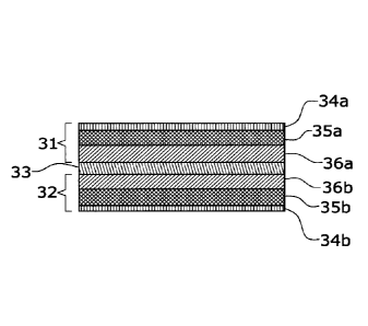
[0044] With reference to FIG. 9, according to a first preferred embodiment,
the effect
pigment with magnetic element comprises a first (31) and a second (32) stacks
of
layers and a magnetic layer (33), said magnetic layer (33) located in between
first
(31) and second (32) stacks of layers and having an out-of-plane magnetisation
with respect to the plane of the pigment.
[0045] The first stack of layers (31) comprises at least an absorber layer
(34a), at least a
dielectric layer (35a) and at least a reflector layer (36a). The second stack
of layers
(32) comprises at least a reflector layer (36b), at least a dielectric layer
(3513) and
at least an absorber layer (34b). The first stack of layers (31) has a
different
configuration than the second stack of layers (32), in that at least one of
the layers
(34a, 34b, 35a, 35b, 36a, 36b) is different from its counterpart, e.g. it is
made of a
different material or it has a different thickness or a different refractive
index; or in
that first (31) and second (32) stacks of layers have a different number of
layers,
producing in any event a double optical effect.
[0046] The absorber layers (34a, 34b) are made up of metallic absorbers,
including
chromium, aluminum, nickel, silver, copper, palladium, platinum, titanium,
vanadium, cobalt, iron, tin, tungsten, molybdenum, rhodium and niobium, as
well as
their corresponding oxides, sulphides, and carbides. Other suitable absorber
materials include carbon, graphite, silicon, germanium, cermet, ferric oxide
or other
metal oxides, metals mixed in a dielectric matrix, and other substances that
are
capable of acting as a nonselective or selective absorber in the visible
spectrum.
Various combinations, mixtures, compounds, or alloys of the above absorber
CA 3065755 2020-03-04
13
materials, known to the skilled in the art, may be used to form the absorber
layers.
In this embodiment, the absorber layer preferably has a thickness of 2 to 40
nm,
more preferably of 3 to 30 nm and yet more preferably of 3,5 to 15 nm, these
ranges
being adequate for all embodiments herein described.
[0047] The dielectric layers (35a, 35b) are made up of high refractive index
materials,
including zinc sulphide, zinc oxide, zirconium oxide (ZrO2), titanium dioxide
(TiO2),
diamond-like carbon, indium oxide (1n203), indium-tin-oxide (ITO), tantalum
pentoxide (Ta205), ceric oxide (Ce02), yttrium oxide (Y203), europium oxide
(Eu203),
iron oxides such as (11)diiron(III) oxide (Fe304) and ferric oxide (Fe2O3),
hafnium
nitride (HfN), hafnium carbide (HfC), hafnium oxide (Hf02), lanthanum oxide
(La203), magnesium oxide (MgO), neodymium oxide (Nd203), praseodymium oxide
(Pr6011), samarium oxide (Sm203), antimony trioxide (Sb203), silicon monoxide
(Si0),
selenium trioxide (Se203), tin oxide (Sn02), tungsten trioxide (W03), and
combinations of those materials. Also, said dielectric layers (35a, 35b) can
be made
up of low refractive index materials, including silicon dioxide (SiO2),
aluminum oxide
(A1203), metal fluorides such as magnesium fluoride (MgF2), aluminum fluoride
(AIF3), cerium fluoride (CeF3), lanthanum fluoride (LaF3), sodium aluminum
fluorides (e.g., Na3AIF6, Na5A13F14), neodymium fluoride (NdF3), samarium
fluoride
(SmF3), barium fluoride (BaF2), calcium fluoride (CaF2), lithium fluoride
(LIE),
combinations thereof, or any other low index material having an index of
refraction
of about 1.65 or less. For example, organic monomers and polymers can be
utilized
as low index materials, including dienes or alkenes such as acrylates (e.g.,
methacrylate), perfluoroalkenes, polytetrafluoroethylene (Teflon), fluorinated
ethylene propylene (FEP) or combinations thereof. The thickness of the
dielectric
layer determines the effect pigment colour and is of the order of 200 to 800
nm.
[0048] The reflector layers (36a, 36h, 41) can be made up of a variety of
reflective
materials, including aluminum, silver, copper, gold, platinum, tin, titanium,
palladium, nickel, cobalt, rhodium, niobium, chromium, iridium, and
combinations or
alloys thereof. Appropriate thickness is preferably from 10 to 2000 nm, more
preferably from 20 to 1000 nm and yet more preferably from 50 to 100 nm, these
ranges being adequate for first and second embodiments described.
[0049] It will be clear to the person skilled in the art that variations of
materials and/or
variations of thickness, all within the acceptable ranges described, with
respect to
the material or thickness of its counterpart layer; and variations of
refractive index
in one of the layers, or a variation in the number of layers in one of the
stacks (31,
CA 3065755 2020-03-04
14
32), will entail an asymmetrical layer structure and therefore the optical
effect
produced by the two stacks of layers (31, 32) will be different.
[0050] With respect to the magnetic layer (33) with out-of-plane
magnetisation, its
composition is Cobalt-based, because due to this mineral crystal structure, it
is
highly suitable to make thin layers with a predominantly perpendicular easy
axis. To
increase the magneto crystalline anisotropy constants, cobalt is allied with
Platinum or chromium. CoPt and CoCr monolayer and multilayer structures can be
used, the monolayer structure being preferable. Stoichiometry of said alloys
are:
Co75Pt25 and Co90Cr10 because these proportions optimize the out-of-plane
anisotropy of the layer. The thickness of the magnetic layer (33) is
preferably from
20 to 1000 nm, more preferably from 30 to 150 nm and yet more preferably from
50
to 100 nm, these ranges being adequate for the first and second embodiments.
[0051] In a variant of the first embodiment, the effect pigment comprises a
luminescent
material which is added to the at least two dielectric layers (35a, 35b).
Suitable
luminescent materials are disclosed in WO 02/040599 A (FLEX PRODUCTS INC.)
23/05/2002 . Addition of the luminescent material is made by the same
deposition
process that will be described hereinafter, by including the luminescent
material
together with the dielectric material in the target employed for the
deposition. In a
further variant, the luminescent material can be incorporated in the form of a
luminescent layer added to each of the stacks of layers (31,32). Suitable
materials
for these layers are the same described in above-mentioned WO 02040599 A. The
luminescent material is added according to the same process applicable to the
other layers which will be referred hereinafter. The luminescent response may
or
may not be in the visible spectrum. In the latter case, the response must be
detected using an appropriate sensor. A key feature of the invention is that
the
luminescent material incorporated to the respective stacks of layers (31, 32)
is
different, thereby the pigment will show a double optical effect in the form
of a
different luminescent response on each of its sides.
[0052] With reference to FIG. 10, according to a second preferred embodiment,
the effect
pigment with magnetic element comprises a stack of layers (37) and a magnetic
layer (38), said magnetic layer having perpendicular magnetisation. The stack
of
layers (37) comprises an absorber layer (39), a dielectric layer (40) and a
reflector
layer (41), the magnetic layer (38) being located next to the reflector layer
(41). The
material composition and thickness of the layers making up the stack of layers
(37)
and the magnetic layer (38) in this second preferred embodiment are the same
as
described for the first embodiment.
CA 3065755 2020-03-04
15
[0053] With reference to FIG. 11, according to a third preferred embodiment of
the
invention, the effect pigment with magnetic element comprises a stack of
layers
(42) comprising an absorber layer (43) and a dielectric layer (44), with the
same
features as described above. The stack of layers (42) does not comprise a
reflector
layer. The magnetic element is a layer (45) made of A1203 containing magnetic
nanoparticles. Due to the aluminium-based composition, this element also works
as
reflector layer. To achieve a perpendicular anisotropy, said magnetic layer
(45)
contains embedded nickel particles. Approximate nickel particle size is 20 nm.
The
thickness of the magnetic layer (45) is preferably from 10 to 2000 nm, more
preferably from 20 to 1000 nm and more preferably from 50 to 150 nm.
[0054] With reference to FIG. 12, according to a fourth preferred embodiment
of the
invention, the effect pigment with magnetic element comprises a first stack of
layers (46) and a second stack of layers (47), each of them comprising an
absorber
layer (48a, 48b) and a dielectric layer (49a, 49b), with the same features as
described above and neither of them comprising a reflector layer. The magnetic
element is a layer (50) made of A1203 containing magnetic nanoparticles. Due
to
the aluminium-based composition, this element also works as reflector layer.
To
achieve a perpendicular anisotropy, said magnetic layer (50) contains embedded
nickel particles. Approximate nickel particle size is 20 nm. The thickness of
the
magnetic layer (50) is preferably from 10 to 2000 nm, more preferably from 20
to
1000 nm and more preferably from 50 to 150 nm.
[0055] Claimed pigments conforming to the described embodiments are
manufactured by
deposition of successive layers' materials onto a carrier substrate, according
to the
known technique of physical-vapor-deposition (PVD). The carrier is preferably
a
flexible web, e.g. a release-coated polyethylene there- phthalate (PET) foil.
The
vapor-deposition can be carried out as a roll-to-roll process in a high vacuum
coater. The materials are evaporated using material- specific, appropriate
evaporation sources and processes known to the skilled person, such as
sputtering,
reactive sputtering, magnetron sputtering, thermal evaporation, electron-beam,
laser-beam assisted evaporation or ion-beam evaporation.
[0056] Magnetic layers (33, 38) made of CoPt alloy as incorporated to the
first and second
embodiments are obtained by electron beam co-evaporation, a technique that can
also be employed to produce the stack (37) or stacks (31, 32) of layers. The
composition of the magnetic layer (33, 38) is controlled by changing the
deposition
rate of Co, while deposition rate of Pt is held at 0.05 nm/sec. The base
pressure of
the chamber must be approximately 5x10⁻⁹Torr prior to evaporation and well
below
CA 3065755 2020-03-04
16
5x10⁻⁷ Torr during evaporation. According to this process, layers of Co75Pt25
deposited onto A1203 substrates held at temperatures from 180 C to 400 C
exhibit a strong perpendicular magnetic anisotropy of 1.5x10⁷erg/cm3; as
described
in YAMADA, et al. Magnetic properties of electron beam evaporated CoPt alloy
thin
films. IEEE TRANSACTIONS ON MAGNETICS. September 1997, vol.33, no.5,
p.3622-3624.
[0057] Magnetic layers (33, 38) made of CoCr alloy as incorporated to the
first and second
embodiments are obtained by a process whereby both elements are co-deposited
by RE sputtering, from a cobalt target on which a number of electrolytic
chromium
pellets are placed at regular intervals in a grid pattern. The composition of
the layer
is controlled by changing the surface area of the chromium pellets. An alloy
target
of CoCr can also be used for RE sputtering. The RF sputtering is carried out
in an
Argon gas atmosphere after baking the vacuum chamber and the substrate holder
at about 300 C. The background pressure was kept under 2 x 10 -7 Torr. The
thickness of the layer is controlled by the sputtering time. The deposition
rate is
mainly influenced by the RE power density and the Argon pressure. An
acceptable
deposition rate is 0.33 micron/hour, the Argon pressure is 0.01 Torr and the
RE
power density is 0.44 watt/cm2. This process is described at IWASAKI, et al.
Co-Cr
recording films with perpendicular magnetic anisotropy. IEEE TRANSACTIONS ON
MAGNETICS. September 1978, vol.MAG-14, no.5, p.849-851.
[0058] Magnetic layers (45) with reflector properties as incorporated to the
third
embodiment are obtained by sol-gel techniques described as follows in KRAUS,
et
al. Synthesis and magnetic properties of Ni-Al2o3 thin films. J. appl. phys..
1997,
no.82, p.1189-1195. : sol-gel layers are deposited from NiA1204 spinel
precursors
derived by mixing stoichiometric quantities of solutions prepared from nickel
2-
ethylhexanoate and aluminum tri-sec-butoxide in 2-methoxyethanol. The nickel
solution is prepared by mixing nickel 2-ethylhexanoate with 2-methoxyethanol
in a
molar ratio of 1:5, refluxing at 140 C for 12 h, centrifuging, and decanting
to
produce a 0.6M solution. In a separate flask, aluminum tri-sec-butoxide is
dissolved
in 2-methoxyethanol in a molar ratio of 1:10 and refluxed for 30 min at 140
C. The
volume is reduced by distillation at a temperature of 140 C and 200 mm Hg.
Acetic acid is then added to the aluminum precursor in a molar ratio of 7:1.
This
solution is stirred at 120 C until clear, and cooled to room temperature.
Magnetic
layers (45) are produced by spin casting a 0.4M N1A1204 precursor solution at
3000
rpm onto (100) Si wafers, (1102) A1203 electronic grade substrates, or
polished
fused silica plates. Layers of various thicknesses are formed by the
successive
CA 3065755 2020-03-04
17
application and drying of the precursor solution. As-deposited films are
converted
to spinel by heating at 1200 C in air for 5 min. Once formed, the spinel is
reduced
to Ni+A1203 in hydrogen (low p02) using a Kidd Electronics rapid thermal
annealed
(RTA). The RTA is purged three times with 99.99% hydrogen and the reduction is
carried out at 950 C using a heating rate of 50 C/s, for 5 min in 200 cc/min
flowing H2.
CA 3065755 2020-03-04