Note: Descriptions are shown in the official language in which they were submitted.
'
RUBBER EDGE SEAL. RETENTION DEVICE
BACKGROUNV0P.11A:':INVENTION
Field of the Invention .. [0001] The present invention
relates : generally to 'assemblies on door panels for
transit vehicles, such as subway and comilu4erlailca0.: More particularly, the
present
invention relates to a sealingassembly-iiywhich a sealing member is assembled
within a
C-shaped channel member:
Description of Related Art
[0002] Several designs ,of transit : door panels fitted with-
rubber edge seals have been
described in the prior art:400Utilized:O4AranSit railcara. In several of these
designs, the
door panel structure is made frolu'extrudedprofiles;:pioSt frequently aluminum
profiles.
The extruded profile easily lends itselftoProviding continuous built-in
retention feature
for the rubber seal member. One example of such Atiuilt-in retention feature
for the rubber
seal member applied to the: extruded profile iS disclosed in United States
Patent Application
, .
Publication No. 2017/0305247.
[0003] A prior art example cif :a tetention3T6.atigo'gipti4tio channel members
is shown
in FIG. 1. When stock stainless steel Cshaped: channel members are used as
structural
members. of the panel, a:differ* method must be used.: to create the retention
feature on
the channel memberS. The retention featOrei:islimpleniented :in this example
by bending
the edges of wings of the C-shaped channel taftber toward the inside of the C-
shaped
channel member to form two L=estenticin.400)Øflif.Fetaining the seal member
on the channel
member. This method, *hile, inexpensiv;V:nanufacture, does not provide optimum
results because it is difficult to obtain cOnsigtent,and:accurate bending
angles and lengths
of the wings. Moreover, the wings do not entirely fill the mating groove of
the rubber seal
member. These drawbacks
altioSei:aasenibly of the seal member on the channel
member, which allows the seal MembettOlOOk sideways, illustrated in FIG. 1.
[0004] An alternative example of a retention feature is shown in FIG. Z In
this example,
the rubber seal member is rigidly-faStened!V:i:a..00cpfid C-shaped channel
member known
as a seal carrier. The seal :carrierhas:SIO&::01,Jta side disposed at an angle
with respect to
its length. These slots mate with piiis':dispOsed iUi!the: firstg-..thaped
channel member that
-1-
.: :
Date recue/Date received 2023-04-10
is part of the door panel struenire, so that the seal carrier/rubber seal
member assembly is
hung on the door panel edge: This solution :provides good seal retention but
has the
disadvantage of adding to the overall weight Of 'aitid :enat of the door
panel, including
substantial additional labor forassembly;
toithe need for the additional seal carrier and
pins inserted into the atot C4shood channelvember on the door panel edge. The
cost of
the seal carrier is also intreaSed"When the:dOorpanel prOie: is curved.
summmor OTflEThVENTION
[0005] According to an eltatripWathepreadtit disclosure, a rubber edge seal
retention
device is provided that features both cost-effectiveness., and repeatable and
excellent
retention performance for transit door parols=-using :a. stainless steel C-
channel structure.
The device adds little to no extra weight to the door panel. The device
requires only one
C-shaped channel member Instead of bending C-shaped channel member to create
retention wings and hooks, as described -abOve, a punch and die is used to
create
depressions in the C-shaped 'channel mentbet Each:depresSion is a few inches
long and
spaced apart by a few inclies.,. The width Or the depression is adjusted to be
substantially
the same as the width of the.:niatitig grooVe.::Of: *lubber:seal member. The
punch and die
manufacturing process is inexpensive, highjy.repetitiyoi-.andochieves good
manufacturing
tolerances. The rubber seal member may: be remOted fOr maintenance purposes.
The
device provides sufficient retention On: the: tubber seal member to preclude
ridership
vandalism, while being easily installed, :The device. may be installed on
stainless steel
structure door panels used on railcar tranaltarid conlintiter vehicles.
[0006] According to an :embodiment of.the present .disclosure, a rubber edge
seal
retention device is provided. The device includes a rubber seal made up of a
front section
and a back section. The baek section::has4 Wedge and:two rectangular retention
grooves
having a depth and a:width disposed on eaokiaide Of the *mgt. The device also
includes
a metallic Cchatitiei made up or first and:,k;Second wings, the wings being
substantially
parallel, and a section joining the parallel wings The C,channel has
depressions disposed
on both the first and the:second wing of thechannel along ita!long axis with
the depressions
on the first wing substantially facing the depteasiono on the. second wing.
The depressions
are created using t.piMokand.die:10oVor :alternate method of producing the
same with
substantially similar accuracy; Eacbdeptessiowi made of one straight section
parallel to
-2-
CA 3066131 2019-12-24
its associated wing and locatedanbstantially.away.from its associated wing and
toward its
opposite wing so as to define the 'depth oftheldepression, and two curved
sections joining
the straight section with its associated:Whig. The straight and curved
sections are obtained
by maidng two cuts, both parallel to the edge: ef the Gichannel and spaced
apart by the
width of the straight section and by Plastic: diaplapenient of the material
located between
the two cuts. The depth and Width Of each depression is substantially same as
the depth
and width of the mating rubber seal retention groove The :C-channel may have
adjacent
depressions on the same Wing or s-ubstantially spaced-apart depressions. The
rubber seal
may have a cavity disposed: .*r.ithin the wedge cross section to facilitate
insertion of the
rubber seal into the C-chatinel.
[0007] According to a particular exampleOf the prOSent disclosure, a sealing
system for
an openable panel on a vehicle is provided,. The sealing system comprises a
channel
member configured to be: disposed on: :The openable panel and extending along
a
longitudinal alas. The Channel 'blether comprises at least.: two side portions
extending
substantially parallel to each other along the. longitUdirial aida and a
recess defined between
the at least two side portions. The .at least twe sideportions each comprise a
plurality of
depressions defined therein &lending filongthe longitudinal axis and into the
recess of the
channel member, the depressions arranged facingeach Other. along the
longitudinal axis.
The system also compriseaa seal memberfastened to the channel member and
extending
along the longitudinal axis. The seal :member Comprises a proximal portion
disposed
within the recess of the channel meniber and a:diStal portion extending away
from the
channel member. The prOximal portiOn the seal rdereber has grooves defined on
opposing sides thereof extending along the longittclhial axis. The plurality
of depressions
on each side portion of the channel are received in a respective groove on the
seal member
to fasten the seal member to the channel Member.
[0008] According to pother particular example Of the. Present disclosure, an
openable
panel for a vehicle is provided. The openable
comprises a rigid panel configured to
be movably connected ti-a.vehicle Wall in an: opening defined in the vehicle
wall, and a
sealing system disposed .00 At least One, .side: of the rigid panel. The
sealing system
comprises, a channel member configured: be .disposed on the openable panel and
extending along a longitilditiOt The
Channel ;member comprises at least two side
CA 3066131 2019-12-24
,
portions extending substantially parallel to. pack-other along the
longitudinal axis and a
recess defined between the at least two side portions. The at least two side
portions each
comprise a plurality of depre$SiOns dOned therein eXtending along the
longitudinal axis
and into the recess of the channel inentberJhedeptesSions arranged facing each
other along
the longitudinal axis. The system also comprises a scalinember fastened to the
channel
member and extending along the longitudinalaXiS,: The seal member comprises a
proximal
portion disposed within the recess.:of the channel member and a distal portion
extending
away from the channel member, The proximal portion Of the seal member has
grooves
defined on opposing sides thereof extending.,along the longitudinal axis. The
plurality of
depressions on each side portion of the channel are received in a respective
groove on the
seal member to fasten the seal member to the channel member.
[00091 According to anothetparticular :07t.aMpleof the present disclosure, a
method for
assembling the above-described sealing :SyStern=: iS :provided. The method
comprises
providing the channel member, fomfing thephtrality: of depressions in the side
portions of
the channel member by punching inward. the Side portions of the channel member
at a
plurality of locations along the longitudinal axis and inserting the proximal
portion of the
seal member into=.:the:reeess of the oharinclffiernber such that the plurality
of depressions
engages the grooves in the opposiog gide0 oftheSealmember.
[00101 These and other features and characteristics of the present invention,
as well as
the methods of operation. and ftinctions of the related- elements of
structures and the
combination of parts and economies of manufacture, will become more apparent
upon
consideration a the following 'description: and with reference to the
accompanying
drawings, all of which forth !part of this specifiCation, wherein like
reference numerals
designate corresponding 'parts in the various fignre.s: It is to be expressly
understood,
however, that the drawings are fer:the purpose of illustration and description
only and are
not intended as a definition of the: linlita Of:the !inVention. As used in the
specification and
the claims, the singular forms:of:4W', 'an!',:. and "the!' inelude plural
referents unless the
context clearly dictates otherwise.
BRIEF DESCRIPTIONOF THE DRAWINGS
[00111 FIG. 1 is a cross-sectional view of ".a :retention mechanism for a door
panel
member according to a prior art example;
CA 3066131 2019-12-24
[0012] FIG. 2 is a side,VieW and crosseetiOnal-: view of a retention mechanism
for a
door panel seal member according to motor prior #t example;
[0013] FIG: 3 is a perspective Vie* of APOrtiOn of a __________________
vehicle having an openable
door panel according to an exatnple-of the present cligelOsure;
[0014] FIG. 4 is a pet tie
view ofaõ: channel member of a sealing system for an
openable door panel according to an examle.ofthe present:disclosure;
[0015] FIG. 5 is an enlarged perspective View of the channel member taken from
area V
shown in FIG. 4;
1.0016.1 FIG. 6 is:A PersPeeti*.e view 'cf the channel member of FIG. 4 with
door skins
mounted on the channel member;
[0017] FIG. 7 is a perspective view oft*. sealing system with a seal member
fastened
to-the channel member of FIG. 4 aecord*:::td'ffn example of the present
disclosure;
[0018] FIG. 8 is a cross-sectional view -------------------------------- of.
the sealing system of FIG. 7 taken along
lines VIII-VIII shown in and
[0019] 'FIG. 9 is a cross-sectional view Of the sealing :System of FIG. 7
taken along lines
IX-IX shown in FIG. 8:
DETAILED DESCRIPTION OF TM:INVENTION
[0020] For purposes of the description tiereinafter; the terms "end", "upper",
"lower",
"tight", "left", 'vertical',,"hOrizOntal",, "top"; "bottom", "lateral",
"longitudinal", and
derivatives thereof shall relate to the invention as it: is:. oriented in the
drawing figures.
However, it is to be -nriderstood that the 'invention may assume various
alternative
variations and step sequences, except where expressly specified to the
contrary. It is also
to be understood that the specific deyicesandprocesses illustrated in the
attached drawings
and described in the followitig:vecification.are simply exemplary embodiments
or aspects
of the inVention. Hence, specific dirnensionswgt Pei& PhySical characteristics
related to
the embodiments or aspects disclosed herek,arenot to be considered as
limiting.
[0021] With reference te FIG.. 3; a transit vehicle 10, such as a subway car,
trolley car,
other rail transit vehicle;:or:siinilar vehicle; IS;Sh*naceeircling to an
example of the present
disclosure. The vehicle 10 includes a door -Assernbly that includes a pair of
outside bi-
parting rigid openable panels. Or doors 12, 14 and' a door operator system 22.
As shown,
the openable panels :12,14 are .cloSed and the transit vehicle 10 is stopped
at a platform 16.
-5-
CA 3066131 2019-12-24
,
The openable panels 12, 14 cover a passenger:portal or opening 18 formed in a
wall 20 of
the transit vehicle 10. The openable panels 1.2., 14 are disposed adjacent to
the wall 20 and
are slidably suspended from the door operatotilsystetn 22, which is disposed
on the wall 20
above the door opening 18. The door operater:Systern22Moves the pair of
openable panels
12, 14 in opposing directions along the door:Opening 18 between open and
closed positions.
According to another example of the present :disclosure, only a single
openable panel 12
may be provided to the opening 18. The door operator- system 22 moves the
single
openable panel 12 between the open and closed:positions.
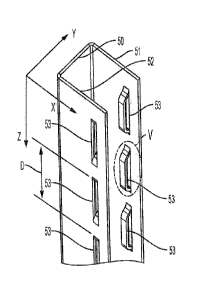
[00221 With reference to FIGS. 4,9, one Of both of the openable panels 12, 14
has a
sealing system or rubber edge seal retention:devide according to an example of
the present
disclosure disposed on at least one side thereof for sealing an engagement
between the
openable panels 12, 14 and/or an engagement between one openable panel 12 and
the wall
20 of the transit vehicle 10 and/or-for sealing: a. gap between one or two
openable panels
and the wall 20 of the transit Vehicle:10. Stich a gap may be formed between
the top of the
openable panel 12, 14 and the wall 20 of the *Olt ::itthiCle 10 or between the
trailing edge
of the openable panel 12, 14 and thewall 20 Odle transit vehicle 10. It is to
be appreciated
that the openable panel, described below with,reference to FIGS. 4-9, may be a
window or
other type of panel other than a door for entry and exit ofpassengers from the
transit vehicle
10.
[00231 As shown in: FIG 4, the scalnig :ay:stein includes a metallic C-shaped
channel
member 50 where the two side portions .or wing 51, 52 of the channel member
50 have
been punched with depressions 53 extending over the whole length of the
channel member
50. The channel member 50 is configured dispOsed on an openable panel, such as
one of
the openable door panels:12;14 .deseribedaboye with reference to FIG. 3, and
extends
tdong a longitudinal clireetion or axis Z. The:wings 51,52 Wend substantially
parallel to
each other along the longitudinal axis Z, and a: .recesS is :defined between
the two wings 51,
52. Both wings 51, 52 include a plurality Of
depressions 53 defined therein extending
along the longitudinal axis Z and into the recess of the channel member 50.
The
depressions 53 are arranged facing each her or: at least substantially facing
each other
along the longitudinal axis Z.
-6-
CA 3066131 2019-12-24
3 ,
[00241 As shown in FIG. 5, which provides a detailed View of a single
depression 53,
each depression is formed byg.:Straight reetarwlar section 54 joined to the
respective wing
51 of the channel member 50 by t*Ck! CurVedSections 55, 56 disposed at either
end of the
straight section 54. The straight tion 54 has,a width A .and a length C and
defines a
depression : depth B. As shown in Ka 4, the
Of depressions 53 in each wing 51,
52 have a repetition pitch O.: The depressions 53 On One wing 51 of the
channel member
50 are positioned to be sObstantially facii...., level in the Z and X
directions of FIG. 4,
the depressions 53 in the. other wing 52: This..layont 'causes maximum
retention force of
the rubber seal member 60, which is pinched between the facing depressions 53,
as shown
in:FIGS. 7-9.
100251 As shown in F.j0.4. 6.; doer panel:Ski:OS:57, 58 are fastened to the
channel member
50 on:each wing 51, 52.... The depressionS=aareferified:irilhe wings 51, 52
along a line in
each wing 51, 52 that is located in, the X direction sufficiently away from
the edge of each
wing 51, 52 so that the door panel
can:.be bent around the edges of the wings
51, 52 and allow for connection of the door skinS157,:: s_g to the channel
member 50.
[00261 It is to be appreciated that the Channel trierribet 50 may be formed
from any
Material, such as stainleas:steel oratimainAM,:foUrid:to be suitable to those
having ordinary
Skill in the art. The charMel Merriber 50:andithe :wings :51, 52 may also have
a different
shape configuration other than C-shaped, Which is found to be suitable to
those having
ordinary skill in the art. The depressions 53 may also be formed with
different
configurations, at different Sizes;: andat different positions and spacing
along the X, Y, and
Z directions of the channel:Member 50 a$:found to be suitable to those having
ordinary
skill in the art. According to an alternative example :Of the present
disclosure, the
depressions 53 have a minimal pitch spacing p along the longitudinal axis Z
such that the
depressions 53 are formed subStantiallyadjacOat to each other.
[0027] As shown in FIGS. 7-9, the rub Seal member 69 is mounted on and
fastened
to the channel member 50 disposed on the edgeof the openable panel 12 and
extends along
:the longitudinal axis Z of the channel mem* 50. The seal member 60 is
retained on the
channel Member 50 by the:.depreaSioris .53, engaged within the retention
grooves 61, 62
formed in the seal member 60. The seal rneMher 60. inclndea a prOXimal portion
disposed
within the recess of the channel member 50 between the wings 51, 52 and a
distal portion
-7-
CA 3066131 2019-12-24
extending away from the channel member 50. The proximal portion of the seal
member
60 includes a wedge profile 64 facing the bottom of the channel member 50. The
seal
member 60 may also have a cavity 63 defined within the wedge 64. The wedge 64
is
provided to facilitate assembly of the seat member 60 on the openable panel 12
by forcing
the wedge 64 into the recess of the channel.member 50, This can be
accomplished using a
mallet or similar tool. The cavity 63 additionally facilitates insertion of
the wedge 64 into
the recess of the channel member 50. The retention grooves 61, 62 are defined
on opposing
sides of the proximal portion Of the seal member 6Q adjacent to the wedge 64
and extend
along the longitudinal axis Z.
[00281 Each depression 53 is :received within and mates with the respective
retention
groove 61, 62 of the seal member 60 to fasten the seal member 60 to the
channel member
50. Each depression 53 is mated within the respectiYe tete,ntion groove 61, 62
without a
substantial void being formed between the dereSSion 53 and the retention
groove 61, 62
with respect to both the width F and the depth E of the retention groove 61,
62. According
to a particular example of the: present disclosure; the depth B and width A of
each
depression 53 is equal to or ;substantially cqual to the depth E and the width
F of the
respective groove 61, 62 in the seal member 60.
[0029] It is to be appreciatathat the sealmember 60 may be formed from rubber
or any
other material found to be suitable to those having ordinary skill in the art.
It is also to be
appreciated that the seal member 60, including the. wedge 64, the cavity 63,
and the
retention grooves 61, 62, may beformed according to any shape configuration
found to be
suitable to those having ordinary skill in the art. According to some
examples, the proximal
portion of the seal member ............................................. 60
May be fonnecl without the wedge 64, and/or the proximal
portion may be formed without the cavity 63.
[0030] According to an example of the present disclosure, a method of
assembling the
above-described sealing system or rubber edge: seal retention device is
provided. A
plurality of depressions 53 is formed in the side portions or wings 51, 52 of
the channel
member 50 by punching the wings 51, 52 inward at a plurality of locations
along the
longitudinal axis Z. According to a. particular example, the depressions 53
are formed
using a punch and die. This Method provide typical dimensional tolerances of
+/- 0.005
inch along the X and Y directions, Which are the most important axes for
controlling a
-8-
CA 3066131 2019-12-24
precise mating of the depressions 53 with teletention grooves 61, 62.
Tolerance control
along th:e Z direction is::of lesser importance:, It is tO appreciated that
any other method
and tooling that provides similar dimensional control and tolerances may be
utilized in
place of a punch and die system and nieth4
[00311 After the depressions 53 are formed in the channel member, the proximal
portion
of the seal member 60 is inserted into thelecess of:the channel member 50 such
that the
plurality of depressions 53 engages the retention grooves 61, 62 in the
opposing sides of
the seat member 60.
[00321 According to .a.particular examrile Of the preSent disclosure, the
channel member
50 and the seal member 60 can be appliedito..operiablevanels 12, 14 having
curved edges
SO long as the radius ofcurvatureiSsnffi.Oieritly loge. The depressions 53 are
first formed
in a straight channel member 50. The ehannettriember 50 is then bent to obtain
the desired
curvature profile corresPoncling to the curveclette of operiable panels 12,
14. For openable
panels 12, 14 having a profile with two sections joined-by a sharp bend, the
depressions 53
may be located in the Z direction so that they do not overlap with the sharp
bend and so
that they still substantially face each other ofter:bendiritof the: channel
member 50.
[00331 According to another particular example ofthe present disclosure, a
fastening
. means is provided at the extremities of the assembled channel member 50 and
seal member
60 to further solidify thaaSsegibly and:prevent:unwanted disconnection of the
seal member
60 from the channel member 50; Example4 Of srich fastening means are provided
in United
States Patent Application Publication No; 2017/0305247.
[00341 According to the above-described examples of the present disclosure,
the
extraction force of the seal member 60 frOrk:the channel member 50 is
important to the
overall construction and functioning of the:Sealing system.. The extraction
force should be
Sufficiently high such that the seal member :60 cannot be pulled away from the
channel
member 50 by hand pulling. 1716Wever, :it Should also be possible to remove
the seal
member 60 from the channel member 50 with :a:reasonable amount of force to
allow for
periodioreplacerrient olthe seal member..60: isóai
of the seal member 60 can
normally be accomplishedby accessing the,ripper Hower ends of the assembled
channel
member 50 and seal meniber..:60 and prying.off the seal member 60 at one of
the ends.
Assistance can be provided by a tool inserted between..the channel member 50
and the
CA 3066131 2019-12-24
,
wedge 64 of the seal member 60 to facilitate initiation of the removal of the
seal member
60.
[0035] According to a particular example :Of, thepresent disclosure, the
configuration
and dimensions of the depressions 53 the channel member 50 and the retention
grooves
61, 62 of the seal member-60 are optiniized=to obtain an appropriate balance
between an
insertion force that is sufficiently low and:.: extraction, force that is
sufficiently high to
prevent unwanted removal, but sufficiently :liamK to allow for removal during
regular
maintenance. The main pararneteracontroliing the insertion and extraction
forces include
the dimensions of the straight section 5*0f0Oh:depression 53, including the
width A, the
length C, the depth B, and the pitch D between adjacent depressions 53. The
width A and
depth B should substantially correspond to the:Width and depth E of the
retention grooves
61, 62 of the seal member 60 The main parameters also include the duro
hardness of the
seal member 60, the angled.shape of thewedge 6.4 :and the: shape and
configuration of the
cavity 63.. within the wedge 64, if present In any typo example of the present
disclosure,
all of these parameters are selected to obtain. thedesired insertion and
extraction forces.
[0036] According to theabevekleseribesiexaniples, a sealing system or rubber
edge seal
retention device is provided that adds minimal weight to the openable panels
12, 14. The
sealing system or rubber edge seal retention ,.device has a low material and
manufacturing
cost The sealing system or rubber edge:seatete0o4.device provides for easy
installation
of the seal member 60 on the. openablepariels: 12, 14 and allows for
calibration of the
extraction force required toremove the seal Meniber 60 from the channel member
50. The
sealing system or rubber edge seal retentiOn: device provides for good control
of
manufacturing tolerances:ler: repeatable retention performance. The sealing
system or
rubber edge seal retention: device aceointriOdates openable panels 12, 14
having curved
profiles. The sealing system or rubberedgeteal retention device can be used
for installing
the seal member 60 on the leading edges, the trailing edges, and/or the top
edges.
10037] Further examples ofthe present:diselegure will now be described in the
following
numbered clauses.
[0038] Clause 1: A sealing system for ati onenable panel (12, 14) on a vehicle
(10),
!comprising: a elatiriel member (50 eori#g*ecl to be disposed on the openable
panel (12,
14) and extending alonga longitudinal axis..(Z); the channel member (50)
comprising at
-10-
CA 3066131 2019-12-24
. õ
least two
side
portions (51, 52) extending sabstantiany parallel to each other along the
longitudinal axis
(Z) and a recess defined between the at least tvvo side portions (51, 52), and
the at least two
side portions (51, 52) each comprising a plurality of depressions (53) defined
therein
extending along the longitudinal axis (Z) and into the recess of the channel
member (50),
the depressions (53) arranged facing each:other Along the longitudinal axis
(Z); and a seal
member (60) fastened to the channel m,ember (50) aix1 eVencling along the
longitudinal
axis (Z), the seal member (60) comprising a proximal portion disposed within
the recess of
the channel member (50) ancl..a distal portion extending away from the channel
member
(50), the proximal portion of the seal member (60) having grooves defined on
opposing
sides thereof extending along the longitudinal axis (Z),.and the plurality of
depressions (53)
on each side portion (51, 52) of the than being received in a respective
groove (61, 62)
on the Seal Member (60) to fasten the seal:member. (60) to the channel member
(50).
[0039] Clause 2: The sealing system according to .clause. 1, wherein the
plurality of
depressions (53) is formed in the side portions (51, 52) of the channel member
(50) by a
punch and die.
(00401 Clause 3: The sealing system adecrditig to clause.! or clause 2,
wherein each of
the plurality of depressions (53) comprises a straightsection (54) extending
parallel to the
side portion (51, 52) and two curved sections (55, 56) connecting the straight
section (54)
to the side portion (51, 52).
[0041] Clause 4: The sealing system according to any one of clauses 1-3,
wherein a
depth (B) and width (A) of each of the pl urality of depressions (53) in the
channel member
(50) is substantially the same as a depth (E) and width (F) of the respective
groove (61, 62)
in the Seal member (60).
[0042] Clause 5: The sealing system according to any one of clauses 1-4,
wherein the
depressions (53) in each side portion (51, 52) of the channel member (50) are
spaced apart
along the longitudinal axis V).
[0043] Clause 6: The sealing system according to any one of clauses 1-5,
wherein the
proximal portion of the seal member (60) cmnprises a wedge (64).
-11-
CA 3066131 2019-12-24
[00441 Clause 7: The sealing system according to clause 6, wherein the wedge
(64)
comprises a cavity (63) defined therein to facilitate insertion of the
proximal portion of the
seal member (60) into the recess of the *Magi Member (50).
[0045] Clause 8: The sealing system ate:ogling=tO.any one of clauses 1-7,
wherein the
plurality of depressions (53) is formed in the side portions (51, 52) of the
channel member
(50) at positions configured to allow for connection of door skins (57, 58) to
the channel
member (50).
[0046] Clause 9: The sealing system according to any one of clauses 1-8,
wherein the
channel member (50) is a C-shaped channel member.
[0047] Clause 10: An openable panel (12, 14) for a vehicle (10), comprising: a
rigid
panel configured to be movably connectedIO:a Vehicle:wall (20) in an opening
(18) defined
in the vehicle wall (20); and a sealing systerndispOsed on atleast one side of
the rigid panel
(12, 14), the sealing system COMPrising; k channel member (50) configured to
be disposed
on the openable panel (1:2, 14) and eitending along a longitudinal axis (Z),
the channel
member (50) comprising at least two side pOrtions (51, 52): extending
substantially parallel
to each other along the longitudinal axis (Z) anda recess defined between the
at least two
side portions (51, 52); :and the at least two side (51,
52) each comprising a plurality
of depressions (53) defined. therein- extending'alortg: the longitudinal axis
(Z) and into the
recess of the channel member (50), the depressions (53) arranged facing each
other along
the longitudinal axis (Z); and a seal member (60) fastened to the channel
member (50) and
extending along the longitndinal. axis (Z)Ohe seal, member (60) comprising a
proximal
portion disposed within the. recess .of the:, 04401 member (50) and a distal
portion
extending away from the channel member! (54 the proximal portion of the seal
member
(60) having grooves defined on opposing *ides thereof extending along the
longitudinal
axis (Z), and the plurality of clepressiona(53)on each side portion (51, 52)
of the channel
= = =
being received in a respective groove 01; p on the seal member (60) to fasten
the seal
member (60) to the channel Member (50),
[0048] Clause 11: The openable panel (12, :14) according to clause 10, wherein
the rigid
panel comprises a vehicle door panel.
[0049] Clause 12: The openable panel: (12i. 14) according to clause 10 or
clause 11,
wherein each of the plurality of depressions (53) comprises a straight section
(54)
.12-
CA 3066131 2019-12-24
extending parallel to the side portion (51, 52) :and two curved sections (55,
56) connecting
the straight section (54) to the side portion (51, 52).
[0050] Clause 13: The operable panel (12, 14) according to any one of clauses
10-12,
wherein a depth (B) and width(A) of each of the plurality of depressions (53)
in the channel
member is substantially the same as a depth (E) and width (F) of the
respective groove (61,
62) in the seal member (60).
[0051] Clause 14: The openable panel (12, 14) according to any one of clauses
10-13,
wherein the depressions (53) in each side portion (51, 52) of the channel
member (50) are
spaced apart along the longitudinal axis (Z).
[0052] Clause 15: The openable panel (12, 14) according to any one of clauses
10-15,
wherein the proximal portion of the seal Member (60) comprises a wedge (64).
[0053] Clause 16: The openable panel (12,. 14) according to clause 15, wherein
the
wedge (64) comprises a cavity (63) defined therein to facilitate insertion of
the proximal
portion of the seal member (60) into the recessOf the channel member (50).
[0054] Clause 17: The openable panel 02, 14) according to any one of clauses
10-16,
wherein the channel member (50) is a C-shaped channel member.
[0055] Clause 18: A method for assembling the sealing system according any one
of
clauses 1-9, comprising: providing the channel member (50); forming the
plurality of
depressions (53) in the side portions (51, 52) of the channel member (50) by
punching
inward the side portions (51, 52) of the channel member (50) at a plurality of
locations
along the longitudinal axis (Z); and inserting the proximal portion of the
seal member (60)
into the recess of the Channel member (50) stich that the plurality of
depressions (53)
engages the grooves (61, 62) in the opposing sides of the seal member (60).
[0056] Clause 19: The method according to clause 18, further comprising
bending the
channel member (50) to obtain a curvature consesponding to a curved edge of
the openable
panel (12, 14).
[00571 Clause 20: The method according to clause 18 or clause 19, wherein the
depressions (53) are formed with a width (A) and depth (B) equal to a width
(F) and depth
(E) of the grooves (61, 62) in the seal member (60).
[0058] It is to be understood that the invention may assume various
alternative variations
and step sequences, except where expressly specified to the contrary. It is
also to be
-13-
CA 3066131 2019-12-24
,
understood that the specific devices and processes illustrated in the attached
drawings and
described in the specification are simply exemplary .embodiments or aspects of
the
inventiOn. Although the invention has been described in detail for the purpose
of
illustration based on what is:currently consWered to be the most practical and
preferred
embodiments or aspects, it is to be understood that such detail is solely for
that purpose
and that the invention is not limited to the disclosed embodiments or aspects,
but on the
contrary is intended to cover niodifications and equivalent arrangements that
are within the
spirit and scope thereof For .example, it is to be understood that the present
invention
contemplates that to the extent possible, one or more features of any
embodiment or aspect
can be combined with one or more features of any other embodiment or aspect.
-14-
CA 3066131 2019-12-24