Note: Descriptions are shown in the official language in which they were submitted.
CA 03066405 2019-12-05
WO 2018/227009
PCT/US2018/036540
ELECTRICAL OUTLET WITH INTERCHANGEABLE FACEPLATE MODULES
RELATED APPLICATION(S)
[0001] This application is based on U.S. Provisional Application Serial No.
62/516,932, filed June 8, 2017, the disclosure of which is incorporated herein
by reference in its entirety and to which priority is claimed.
FIELD
[0002] Various exemplary embodiments of the invention relate to electrical
outlets.
BACKGROUND
[0003] Electrical devices, specifically electrical receptacles capable of
receiving electrical plugs, generally include two or three sets of blade
apertures, with each set arranged to receive an electrical plug. The
electrical
receptacle or device is sold as a single unit or a multi-pack in home
improvement stores and is then wired in by either a professional electrician
or
by the homeowner if he or she is comfortable with electrical wiring. For the
average homeowner, replacing the electrical device can be expensive due to
hiring an electrician or dangerous should they attempt the replacement
themselves. Different outlet types are increasingly being used in homes,
including USB outlets.
SUMMARY
[0004] According to an exemplary embodiment, an electrical outlet
assembly includes a sub-faceplate having a front surface and first set of
contacts position on the front surface. An outer faceplate includes an outer
surface and an inner surface, the inner surface having a second set of
contacts.
The outer faceplate is releasably connected to the sub-faceplate so that the
first set of contacts connect to the second set of contacts.
CA 03066405 2019-12-05
WO 2018/227009
PCT/US2018/036540
[0005] According to another exemplary embodiment, an electrical outlet
assembly includes a sub-faceplate having a front surface and first set of
contacts position on the front surface. The sub-faceplate is configured to
connect to a receptacle opening. A first outer faceplate includes an outer
surface and an inner surface, the inner surface having a second set of
contacts,
and the outer surface having a first configuration. A second outer faceplate
includes an outer surface and an inner surface, the inner surface having a
third set of contacts, and the outer surface having a second configuration
different than the first configuration. The first outer faceplate and the
second
outer faceplate are selectively, releasably connectable to the sub-faceplate
so
that the first set of contacts connect to either the second or third set of
contacts.
[0006] Another exemplary embodiment includes a method of providing
a modular electrical outlet assembly. A sub-faceplate is provided having a
front surface and first set of contacts position on the front surface, wherein
the
sub-faceplate is configured to connect to a receptacle opening. A plurality of
outer faceplates are provided, each faceplate having an outer surface and an
inner surface, the inner surface having a second set of contacts, and the
outer
surface having different configurations. The outer faceplates are selectively,
releasably connectable to the sub-faceplate so that the first set of contacts
connect to the second set of contacts.
BRIEF DESCRIPTION OF THE DRAWINGS
[0007] The aspects and features of various exemplary embodiments will be
more apparent from the description of those exemplary embodiments taken
with reference to the accompanying drawings, in which:
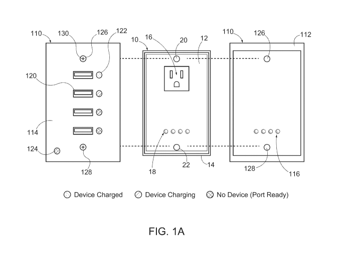
[0008] FIG. IA is a front view of a sub-faceplate and a front and rear view
of an outer faceplate;
[0009] FIG. iB is a side view of an outer faceplate;
[0010] FIG. iC is a side view of another outer faceplate;
¨ 2 ¨
CA 03066405 2019-12-05
WO 2018/227009
PCT/US2018/036540
[0011] FIG. 2 is a front view of another outer faceplate;
[0012] FIG. 3 is a front view of another outer faceplate; and
[0013] FIG. 4 is a front view of a sub-faceplate and a front view of a pair of
outer faceplates.
DETAILED DESCRIPTION OF EXEMPLARY EMBODIMENTS
[0014] Various exemplary embodiments relate to an electrical outlet having
interchangeable faceplates. The faceplates can be interchanged without
exposing a high voltage connection. The outlet can include a base or rear
section that is configured to be recess mounted in a wall or other structural
feature and a front section connected to the rear section. The front section
can
be connected to the rear section by a mechanical fastener, such as a screw or
a
snap fit connection. The front and rear sections may be permanently secured
to one another with any suitable process, including but not limited to plastic
or sonic welding, rivets, or adhesive. The rear section also includes the
inner
working of the electrical device, including but not limited to the electrical
contacts, mounting structures, and any tamper resistant shutters. The rear
section also includes mounting tabs or a mounting strap to mount the
electrical device to an electrical box also well known in the art.
[0015] FIG. iA shows an exemplary embodiment of an outlet having a front
section configured as a sub-faceplate 10. The sub-faceplate 10 includes an
outer surface having a recessed portion 12 surrounded by an outer rim 14. A
set of receptacle openings 16 are provided in an upper portion of the sub-
faceplate 10. The receptacle openings 16 are in a standard three-prong
configuration having hot, neutral, and ground openings. Other outlet opening
configurations can be used including any residential, commercial, or
industrial standard outlets. A first set of contacts 18 are positioned at a
lower
portion of the sub-faceplate 10. The contacts 18 can be spring contacts, pin
contacts, or other suitable contacts. The contacts 18 can provide low voltage,
AC, or DC power, and/or communication (Serial, UART, I2C, SPI) between
¨ 3 ¨
CA 03066405 2019-12-05
WO 2018/227009
PCT/US2018/036540
the sub-faceplate 10 and the faceplate. The contacts 18 offer a low-voltage
connection that is not dangerous to a user or requires a professional
electrician for installation. The sub-faceplate 10 also includes one or more
connecting features, illustrated here as an upper opening 20 and a lower
opening 22 for receiving a fastener such as a screw.
[0016] As shown in FIG. IA, the sub-faceplate 10 connects to an outer
faceplate 110 that is positioned over and at least partially covers the sub-
faceplate 10. The outer faceplate 110 has an inner portion 112 and an outer
portion 114. The inner portion 112 includes a second set of contacts 116
positioned to align with, or otherwise electrically connect to, the first set
of
contacts 18 on the sub-faceplate 10.
[0017] The outer portion 114 includes one or more receptacle openings.
The exemplary embodiment of FIG. IA shows a set of four USB openings 120.
An indicator light 122 is associated with each opening 120. The indicator
lights
can convey the status of the load connected to the openings, for example green
meaning charged, red meaning charging, or blue meaning open or ready to
charge. A faceplate indicator light 124 can be positioned separately from the
opening indicator lights to show the status of the faceplate no. This can
convey to a user that the outer faceplate no is properly connected to the sub-
faceplate 10. The outer faceplate 110 also includes an upper opening 126 and a
lower opening 128 for receiving a fastener such as a screw 130.
[0018] FIG. iB shows the side view and interior design of an outer faceplate
noA with an outer surface 152A and an inner surface 154A. The outer surface
152A is in contact with an environment and the inner surface 154A is in
electrical communication with the sub-faceplate 10 via a set of second
contacts
ii6A positioned to align with, or otherwise electrically connect to, the first
set
of contacts 18 on the sub-faceplate 10. The outer faceplate noA includes an
internal assembly 170A, such as a printed circuit board (PCB), coupled to a
set
of four side view USB openings 120A on one side and the set of second
contacts ii6A on the other side. The internal assembly 170A governs the
¨ 4 ¨
CA 03066405 2019-12-05
WO 2018/227009
PCT/US2018/036540
behavior, intelligence, and communication of outer faceplate noA. The set of
four side view USB openings 120A extend from the outer surface 152A to the
internal assembly 170A. A side view indicator light 122A is associated with
each USB opening 12oA. Based on color, the side view indicator light 122A can
convey the status of a load connected to the corresponding USB opening 12oA.
[0019] FIG. iC shows the side view and interior design of another outer
faceplate noB with an outer surface 152B and an inner surface 154B. The
inner surface 154B is coupled to an extruded back 150 used to nest the outer
faceplate noB to the sub-faceplate 10. The extruded back 150 includes an
internal assembly 17oB coupled to the inner surface 154B on one side and a set
of second contacts 116B on the other side. The internal assembly 170B governs
the behavior, intelligence, and communication of outer faceplate noB.
Communication information and power between the outer faceplate noB and
the sub-faceplate 10 is transmitted via the set of second contacts 116B
positioned to align with, or otherwise electrically connect to, the first set
of
contacts 18 on the sub-faceplate 10. A set of four side view USB openings 12oB
extend from the outer surface 152B to the inner surface 154B and are in
electrical communication with the internal assembly 17oB. A side view
indicator light 122B is associated with each USB opening 12oB. Based on
color, the side view indicator light 122B can convey the status of a load
connected to the corresponding USB opening 12oB. The extruded back 150 in
the illustrated embodiment provides added depth to the outer faceplate noB
to accommodate longer USB openings 12oB.
[0020] FIG. 2 shows another exemplary embodiment of another outer
faceplate 210. The outer faceplate 210 can have an inner portion with a set of
contacts similar to the one shown in FIG. iA. The outer portion 212 includes a
3-prong receptacle opening 214 and a pair of USB openings 216. Indicator
lights 218 are respectively associated with each of the USB openings 216. A
faceplate indicator light 220 can be positioned separately from the opening
indicator lights 218 to show the status of the outer faceplate 210. The outer
¨ 5 ¨
CA 03066405 2019-12-05
WO 2018/227009
PCT/US2018/036540
faceplate 210 also includes an upper opening 222 and a lower opening 224 for
receiving a fastener 226 such as a screw.
[0021] FIG. 3 shows another exemplary embodiment of an outer faceplate
310. The outer faceplate 310 can have an inner portion with a set of contacts
similar to the one shown in FIG. IA. The outer portion 312 includes a wireless
charger 314. A support or connecting feature 316 (illustrated here as a ledge
or
shelf) is positioned below the wireless charger 314 so that a device, such as
a
cell phone, can be supported and aligned with the wireless charger 314. The
support 316 can be configured to contain a light unit that includes an LED
light source that provides illumination in a desired direction. The wireless
charger 314 can include one or more inductive coils that provide inductive
power or charging to the supported device. A charger indicator light 318 can
be associated with the wireless charger 310 to convey the status of the
charger
and/or the connected device. A faceplate indicator light 320 can be positioned
separately from the charger indicator light 318 to show the status of the
faceplate 310. The outer faceplate 310 also includes an upper opening 322 and
a lower opening 324 for receiving a fastener 326 such as a screw.
[0022] FIG. 4 shows another exemplary embodiment of a sub-faceplate
410. The sub-faceplate 410 includes an outer surface having a recessed portion
412 surrounded by an outer rim 414. A switch 416 is positioned in an upper
portion of the sub-faceplate 410. The switch 416 is illustrated as a two
position
(on/off) switch to control an electrical load and can use either a mechanical
or
capacitive mechanism. Other switches, for example a dimmer switch, can also
be used. A first set of contacts 418 are positioned at a lower portion of the
sub-
faceplate 410. The contacts 418 can be spring contacts, pin contacts, or other
suitable contacts. The sub-faceplate 410 also includes one or more connecting
features, illustrated here as an upper opening 420 and a lower opening 422 for
receiving a fastener such as a screw.
[0023] FIG. 4 also shows an exemplary embodiment of an outer faceplate
510. The outer faceplate 510 can have an inner portion with a set of contacts
¨ 6 ¨
CA 03066405 2019-12-05
WO 2018/227009
PCT/US2018/036540
similar to the one shown in FIG. IA. The outer portion 512 includes a display
514. The display 514 can be any type of screen (e.g. LCD, LED, OLED).
Information is provided to the display 514, such as weather, time, charging
status, and load status. The display 514 can be touch sensitive and allow a
user
to access different options or setting and to control one or more electrical
loads in a given area such as a room or a house. A faceplate indicator light
516
can be positioned separately from the display 514 to show the status of the
faceplate 510. The outer faceplate 510 also includes an upper opening and a
lower opening for receiving a fastener such as a screw. In an exemplary
embodiment, the faceplate 510 can communicate with other devices using
WiFi, Bluetooth, Zigbee, or other lower energy communications or near field
communications (NFC).
[0024] FIG. 4 also shows another exemplary embodiment of an outer
faceplate 610. The outer faceplate 610 can have an inner portion with a set of
contacts similar to the one shown in FIG. 1. The outer portion 612 includes an
outer switch 614. The outer switch 614 aligns with the switch 416 on the sub-
faceplate 410 and can include a mechanical or capacitive mechanism. A light
unit 616 is positioned on the bottom portion of the switch. The light unit 616
can include an LED light that provides illumination in a desired direction or
mark the borders of a pathway or room. A faceplate indicator light 618 can be
positioned to show the status of the faceplate 610. The outer faceplate 610
also
includes an upper opening and a lower opening for receiving a fastener such
as a screw.
[0025] In using the components described above, one can provide a
number of different outer faceplates having different configurations. A single
type of sub-faceplate can be installed to a hard-wired connection and
different
outer faceplates can be installed and changed by a user as desired without
exposing the user to a high-voltage connection.
[0026] The foregoing detailed description of the certain exemplary
embodiments has been provided for the purpose of explaining the principles
¨ 7 ¨
CA 03066405 2019-12-05
WO 2018/227009
PCT/US2018/036540
of the invention and its practical application, thereby enabling others
skilled
in the art to understand the invention for various embodiments and with
various modifications as are suited to the particular use contemplated. This
description is not necessarily intended to be exhaustive or to limit the
invention to the exemplary embodiments disclosed. Any of the embodiments
and/or elements disclosed herein may be combined with one another to form
various additional embodiments not specifically disclosed. Accordingly,
additional embodiments are possible and are intended to be encompassed
within this specification and the scope of the appended claims. The
specification describes specific examples to accomplish a more general goal
that may be accomplished in another way.
[0027] As used in this application, the terms "front," "rear," "upper,"
"lower," "upwardly," "downwardly," and other orientational descriptors are
intended to facilitate the description of the exemplary embodiments of the
present invention, and are not intended to limit the structure of the
exemplary
embodiments of the present invention to any particular position or
orientation. Terms of degree, such as "substantially" or "approximately" are
understood by those of ordinary skill to refer to reasonable ranges outside of
the given value, for example, general tolerances associated with
manufacturing, assembly, and use of the described embodiments.
¨ 8 ¨