Note: Descriptions are shown in the official language in which they were submitted.
MULTIPLE SUTURE PASSING DEVICE
CROSS-REFERENCE TO RELATED APPLICATIONS
100011 The present application claims priority to U.S. Provisional App, No.
62/524,776,
filed on June 26, 2017, US, Provisional App. No. 62/549,121, filed on August
23, 2017 and
US. Provisional App. No. 62/549,180, filed on August 23, 2017.
BACKGROUND OF THE INVENTION
1. Field of the Invention
100021 The invention relates generally to a passing suture device and more
particularly,
to a multiple stitch passing suture device for completing a stitch without
withdrawal and
reloading of the inserter.
2. Description of Related Art
100031 In order to gain intra-articular access to the hip joint for
arthroscopic repair of
certain hip pathologies, a surgical incision through the hip's capsule, also
known as a
capsulotomy, is required. After repair of the pathology, it is often desirable
to repair and
close the capsular incision to restore its anatomical function. This technique
requires the
passing of sutures through each leaflet of the incision and the tying of
surgical knots to stitch
it closed. Other suture passing devices currently available have to be
completely withdrawn
from the hip joint in order to be reloaded with suture at the device's distal
and for each stitch.
A more efficient method is needed to complete the stitch.
10041 Therefore, there is a need for a system and method for completing the
stitch
without the additional steps of withdrawal and reloading the inserter
instrument.
10004A1 In the claims and in the description of the invention, except where
the context requires
otherwise due to express language or necessary implication, the word
"comprise" or variations such as
"comprises" or "comprising" is used in an inclusive sense, i.e. to specify the
presence of the stated
features but not to preclude the presence or addition of further features in
various embodiments of the
invention.
SUMMARY OF THE INVENTION
100051 The present invention is directed to, inter alio, a system and
method for
completing one or more stitches without withdrawal and reloading of the
inserter, In one
aspect, the present invention is a suture passer. The suture passer includes a
distal end
having a body with a gripping portion and a suture holding portion. The
gripping potion and
1
Date Recue/Date Received 2021-07-30
the suture holding portion are spaced, defining a recess in the body
therebetween.õõA Ube of
the gripping portion extends toward the suture holding portion and maintains a
needle therein.
The needle is slidable within the tube between a retracted position and an
extended position,.
The 'ludic: has .0 .notelt at its distal end for eatchi,ng and securing a limb
of suture, In the
retracted position, the distal end of the .needle is within the tube of the
Jripping portion and in
the extended position, the distal end of the needle extends into the suture
ltolding, portionõ
The suture holding portion comprises a toggle gate hingedly connected to an
actuator rod, the toggle
gate rotatable between a locked state and an unlocked state, wherein the
toggle gate is configured to
lock a suture in the locked state and to move the suture within the notch of
the needle when being
moved to the unlocked state. In another aspect, the present invention is a
loaded suture passer. The
loaded suture passer additionally includes a suture extending between a first
side of the suture
holding portion and a second side of the suture holding portion.
100061 ha another aspect, the present invention is a method for passing
suture through
au Objectõ, The method comprises the steps of: (i) providing a distal end of
the suture passer
havitill, a both with a Etipping portion and a suture holding portion, wherein
the grippin
portion .T,:nd the, suture holding .portion are spaced, definins a recess in
the body therchetweenõ
a tube of the gripping portion extending toward the suture holding portion, a
needle ,s.hdable
.v,...ithitt the tube Ifici.rn a reti:tc.ted position to an extended position,
the needle having a notch at
a distal end, said notch being sized or otherwise dimensioned to accommodate a
suture;
wherein in the retracted position, the distal end of the needle is within the
tube of the gripping portion and
in the extended position, the distal end of the needle extends into the suture
holding portion; and wherein
the suture holding portion comprises a toggle gate hingedly connected to an
actuator rod, the toggle gate
rotatable between a locked state and an unlocked state, wherein the toggle
gate is configured to lock a
suture in the locked state and to move the suture within the notch of the
needle when being moved to the
unlocked state; (ii) positioning an object having a proximal side and a distal
side in the recess between the
gripping portion and the suture holding portion; (iii) advancing the tube and
the needle through a first
stitching location on the proximal side of the object to the distal side of
the object; (iv) advancing the
distal end of the needle into the suture holding portion; (v) retracting the
needle from the suture holding
portion; (vi) catching a first limb of suture within the notch on the distal
end of the needle; and (vii)
retracting the needle within the tube such that the notch on the distal end of
the needle abuts the tube,
securing the first limb of suture within the notch. In another aspect, the
present invention is directed to a
use of a suture passer for passing suture through an object.
lA
Date Recue/Date Received 2021-07-30
BRIEF DESCRIPTION OF THE DRAWINGS
[0007] One or more aspects of the present invention are particularly
pointed out and
distinctly claimed as examples in the claims at the conclusion of the
specification. The
foregoing and other objects, features, and advantages of the invention are
apparent from the
following description taken in conjunction with the accompanying drawings in
which:
[0008] FIG. 1 is a perspective top view schematic representation of a
distal end of a
suture passing device according to an embodiment,
[0009] FIG. 2 is a close-up perspective top view schematic representation
of the gripping
portion of the device in a loaded configuration, between retracted and
extended positions,
according to an embodiment;
[0010] FIG. 3 is a close-up perspective side view schematic representation
of the distal
end of the clamp tube in the loaded configuration, retracted position,
according to an
embodiment;
[0011] FIG. 4 is a perspective side view schematic representation of the
device in the
loaded configuration, retracted position around a tissue according to an
embodiment;
2
Date Recue/Date Received 2021-07-30
CA 03066474 2019-12-05
WO 2019/005733 PCMJS2018/039406
[0012] FIG. 5 is a close-up perspective top view schematic representation
of the needle
in the suture holding portion of the body of the device according to an
embodiment
[0013] FIG. 6 is a perspective side view schematic representation of the
toggle gate of
the suture holding portion of the device according to an embodiment,
[0014] FIG. 7 is a cross-sectional perspective side view schematic
representation of the
distal jaw of the suture holding portion of the device according to an
embodiment;
[0015] FIG. 8 is a cross-sectional perspective side view schematic
representation of the
toggle gate in the unlocked state and the needle in the loaded configuration,
extended
position, according to an embodiment;
[0016] FIG. 9 is a cross-sectional perspective side view schematic
representation of the
toggle gate in the locked state and the needle in the unloaded configuration,
extended
position, according to an embodiment;
[0017] FIG. 10 is a cross-sectional perspective side view schematic
representation of the
toggle gate in the locked state and the needle in the unloaded configuration,
between the
retracted and extended positions, according to an embodiment;
[0018] FIG. 11 is a perspective side view schematic representation of the
needle in the
unloaded configuration, retracted position, according to an embodiment;
[0019] FIG. 12 is a perspective top view schematic representation of the
toggle gate in
the locked state and the needle in the unloaded configuration, extended
position, according to
an embodiment;
[0020] FIG. 13 is a cross-sectional side view schematic representation of
the distal end
of the device in FIG. 12, according to an embodiment;
[0021] FIG. 14 is a cross-sectional perspective side view schematic
representation of the
toggle gate in the unlocked state and the needle in the loaded configuration,
extended
position, according to an embodiment;
[0022] FIG. 15 is a close-up cross-sectional side view schematic
representation of the
distal end of the needle in FIG. 14;
[0023] FIG. 16 is a perspective view schematic representation of the needle
in the loaded
configuration, retracted position and the device removed from the tissue
according to an
embodiment;
[0024] FIG. 17 is a perspective view schematic representation of the needle
in the loaded
configuration, retracted position and the device removed from the tissue
according to another
embodiment;
3
CA 03066474 2019-12-05
WO 2019/005733 PCMJS2018/039406
[0025] FIG. 18 is a perspective side view schematic representation of the
needle in the
unloaded configuration, between the retracted and extended positions,
according to an
alternative embodiment;
[0026] FIG. 19 is a perspective side view schematic representation of the
needle in the
unloaded configuration, extended position according to an alternative
embodiment;
[0027] FIG. 20 is a perspective side view schematic representation of the
needle in the
loaded configuration, between the retracted and extended positions, according
to an
alternative embodiment; and
[0028] FIG. 21 a close-up perspective top view schematic representation of
the needle in
the unloaded configuration between the retracted and extended positions
according to an
alternative embodiment.
DETAILED DESCRIPTION OF THE INVENTION
[0029] Aspects of the present invention and certain features, advantages,
and details
thereof, are explained more fully below with reference to the non-limiting
examples
illustrated in the accompanying drawings. Descriptions of well-known
structures are omitted
so as not to unnecessarily obscure the invention in detail. It should be
understood, however,
that the detailed description and the specific non-limiting examples, while
indicating aspects
of the invention, are given by way of illustration only, and are not by way of
limitation.
Various substitutions, modifications, additions, and/or arrangements, within
the spirit and/or
scope of the underlying inventive concepts will be apparent to those skilled
in the art from
this disclosure.
[0030] Referring now to FIG. 1, there is shown a perspective top view
schematic
representation of a distal end of a suture passing device according to an
embodiment. FIG. 1
shows a suture passing device 10 comprising a body 12 which extends along a
distal end 14
of the suture passing device 10. In particular, the body 12 extends along a
central
longitudinal axis x ¨ x of the device 10. The body 12 of the device 10
includes a proximal
gripping portion 16 and a distal suture holding portion 18. As shown in FIG.
1, the suture
holding portion 18 comprises the most distal portion of the body 12. Further
shown in the
embodiment of FIG. 1, the griping portion 16 and the suture holding portion 18
are spaced
such that there is a recess 20 in the body 12 between the gripping and suture
holding portions
16, 18. The recess 20 is configured or otherwise sized such that a tissue,
biological body, or
other object may be placed between the gripping portion 16 and the suture
holding portion
18. As described in detail herein, the gripping portion 16 and the suture
holding portion 18
4
CA 03066474 2019-12-05
WO 2019/005733 PCT/US2018/039406
comprise features which facilitate the formation of complete stitches without
the withdrawal
of the device 10 from the tissue (biological body or object) and reloading of
the device 10.
[0031] Turning now to FIG. 2, there is shown a close-up perspective top
view schematic
representation of the gripping portion 16 of the device 10 in a loaded
configuration, between
retracted and extended positions, according to an embodiment. In the
embodiment shown in
FIG. 2, the gripping portion 16 comprises a clamp tube 22 which extends
distally in a
direction substantially parallel to the central longitudinal axis x ¨ x toward
the suture holding
portion 18. In the depicted embodiment, the clamp tube 22 comprises one or
more
protrusions 24 at its distal end 26 for engaging a tissue or other biological
body in the recess
20. However, the clamp tube 22 may also have a smooth distal end 26 (with no
protrusions
24), if desired.
[0032] Still referring to FIG. 2, the gripping portion 16 additionally
comprises a movable
(i.e., slidable) tube or tubular sheath 28 which extends through the clamp
tube 22 also in a
direction parallel to the central longitudinal axis x ¨ x. The sheath 28
extends at least in a
portion of a first inner volume 30 of the clamp tube 22. Further, as also
shown in the
depicted embodiment, the sheath 28 comprises a second inner volume 32 (not
shown), which
is configured and otherwise sized for a movable (i.e., slidable) needle 34. As
shown in FIG.
2, the needle 34 extends within the second inner volume 32 of the sheath 28
and extends in a
direction parallel to the central longitudinal axis x ¨ x. The needle 34
comprises a notch 36 at
its distal end 38. The notch 36 is sized or otherwise dimensioned to
accommodate a suture 40
(or other comparable stitching material).
[0033] As shown in FIG. 2, the needle 34 grabs and secures the suture 40 in
the loaded
configuration when the suture 40 extends through the notch 36 in the needle 34
and the notch
36 is abutted by the distal end of the sheath 28. The distal end of the sheath
28 holds the
suture 40 in place within the adjacent and abutting notch 36. In one
embodiment, a
tensioning mechanism holds the sheath 28 in place relative to the notch 36 in
the loaded
configuration. The tensioning mechanism can be a spring within the clamp tube
22, for
example.
[0034] Referring now to FIG. 3, there is shown a close-up perspective side
view
schematic representation of the distal end 26 of the clamp tube 22 in the
loaded configuration,
retracted position, according to an embodiment. From the loaded configuration
between the
retracted and extended positions, shown in FIG. 2, the needle 34 and the
sheath 28 are moved
proximally along an axis parallel to the central longitudinal axis x ¨ x away
from the suture
CA 03066474 2019-12-05
WO 2019/005733 PCMJS2018/039406
holding portion 18. As the needle 34 and the sheath 28 move proximally, they
are withdrawn
into clamp tube 22 to a loaded configuration, retracted position, as shown in
FIG. 3. In the
depicted embodiment, the clamp tube 22 can be forked, having a pair of
opposing prongs 42
with opening 44 therebetween. The forked distal end 26 of the clamp tube 22
allows the
suture 40 to extend in the openings 44 between the prongs 42 when the needle
34 and the
sheath 28 are withdrawn proximally into the clamp tube 22. In the depicted
embodiment, the
suture 40 extends in a direction approximately perpendicular to the central
longitudinal axis x
¨ x within the openings 44 between the prongs 42. Thus, the needle 34 and the
sheath 28 can
be withdrawn into the clamp tube 22 without disturbing the suture 40.
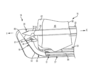
[0035] Turning now to FIG. 4, there is shown a perspective side view
schematic
representation of the device 10 in the loaded configuration, retracted
position around a tissue
46 according to an embodiment. After the suture 40 is loaded into the notch 36
of the needle
34 (FIG. 2) and the needle 34 and sheath 28 are retracted into the clamp tube
22 (FIG. 3), the
device 10 can engage a tissue 46 or other biological body for stitching. In
the depicted
embodiment, a tissue 46 to be stitched is positioned within the recess 20 of
the body 12
between the gripping portion 16 and the suture holding portion 18. When the
tissue 46 is
within the recess 20, the clamp tube 22 is advanced distally along an axis
parallel to the
central longitudinal axis x ¨ x to contact and engage a first stitching
location on the tissue 46.
In the depicted embodiment, the protrusions 24 on the distal end 26 of the
clamp tube 22 are
distally advanced with the clamp tube 22 until the protrusions 24 engage the
tissue 46
[0036] Referring now to FIG. 5, there is shown a close-up perspective top
view
schematic representation of the needle 34 in the suture holding portion 18 of
the body 12 of
the device 10 according to an embodiment. The suture holding portion 18
comprises a distal
jaw 48 with a toggle gate 50. As shown in FIG. 5, the toggle gate 50 extends
between a first
side 52 of the distal jaw 48 and a second side 54 of the distal jaw 48. In the
depicted
embodiment, the distal jaw 48 has a jaw slot 56 which corresponds and aligns
with a toggle
gate slot 58 in the toggle gate 50 (also shown in FIG. 6).
[0037] From the loaded configuration, retracted position shown in FIG. 4,
the sheath 28,
needle 34, and secured suture 40 are advanced from a proximal side 60 of the
tissue 46
through to a distal side 62 of the tissue 46. Once the needle 34 and the
sheath 28 extend
through the distal side 62 of the tissue 46, the needle 34 and the sheath 28
continue to extend
to a loaded configuration, extended position shown in FIG. 5. In the loaded
configuration,
extended position, the needle 34 extends into the toggle gate 50 between the
first and second
6
CA 03066474 2019-12-05
WO 2019/005733 PCMJS2018/039406
sides 52, 54 of the distal jaw 48 of the suture holding portion 18.
Accordingly, the suture 40
carried by the needle 34 enters the aligned toggle gate slot 58 and jaw slot
56. In the depicted
embodiment, a distance that the needle 34 extends distally is greater than a
distance at which
the sheath 28 extends distally. As a result, in the retracted position, the
sheath 28 no longer
abuts the notch 36 of the needle 34. In an embodiment wherein the tensioning
mechanism is
a spring within the clamp tube 22, the spring tension is released between the
notch 36 and the
sheath 28. As the tension is released, the suture 40 is released from the
notch 36, dropping
the suture 40 into the toggle gate slot 58 and the jaw slot 56.
[0038] Referring now to FIGs. 6-7, there are shown various views schematic
representations of the components of the suture holding portion 18 of the
device 10 according
to an embodiment. As shown in FIG. 6, the toggle gate 50 is connected to an
actuator rod 64
via a hinge 51. The actuator rod 64 controls movement of the toggle gate 50 in
a rotary track
66 in the distal jaw 48 of the suture holding portion 18. In the depicted
embodiment, the
toggle gate 50 is curved and comprises a pair of prongs 53 which extend in a
direction
parallel to the central longitudinal x ¨ x axis when the toggle gate 50 is in
the unlocked state
(as shown in FIG. 8). The extension of the prongs 53 from the toggle gate 50
defines the
toggle gate slot 58, which is configured to receive the suture 40 from the
needle 34.
[0039] FIG. 7 shows a cross-sectional perspective side view of the distal
jaw 48 of the
suture holding portion 18 of the device 10, according to an embodiment. The
rotary track 66
extends between the first side 52 (not shown) and second side 54 of the distal
jaw 48. As
shown in FIG. 7, the rotary track 66 has a curved portion 55 to accommodate
the curved
toggle gate 50 and a substantially straight portion 57 to accommodate a
substantially straight
actuator rod 64. The distal jaw 48 comprises a proximal wall 59 and a distal
wall 61 for
defining the curved portion 55 of the rotary track 66. The distance between
the proximal wall
59 and the distal wall 61 is greater than a width of the toggle gate 50 such
that the toggle gate
50 can rotate within the curved portion 55 of the rotary track 66. As shown in
FIGs. 8-10, the
actuator rod 64 moves the toggle gate 50 in both a clockwise and
counterclockwise manner
such that the toggle gate 50 moves away from and towards, respectively, the
rotary track 66.
[0040] Turning now to FIGs. 8-10, there are shown cross-sectional side view
schematic
representations of the suture holding portion 18 moving from the loaded
configuration,
extended position toward an unloaded configuration, retracted position. As
shown in FIG. 8,
the needle 34 extends within the toggle gate 50 in the loaded configuration,
extended
position. In the loaded configuration, extended position, the toggle gate 50
is in the unlocked
7
CA 03066474 2019-12-05
WO 2019/005733 PCT/US2018/039406
state, at its greatest distance from the rotary track 66. The actuator rod 64
is engaged to move
the toggle gate 50 from the unlocked state in FIG. 8 to the locked state in
FIG. 9. As shown
in FIG. 8, the hinge 51 connecting the toggle gate 50 to the actuator rod 64
is within the
curved portion 55 of the rotary track 66 when the toggle gate 50 is in the
unlocked state. To
move the toggle gate 50 to the locked state, the actuator rod 64 is moved or
otherwise pulled
proximally within the rotary track 66, pulling the hinge 51 into the
substantially straight
portion 57 of the rotary track 66. In the locked state, the toggle gate 50 is
at its smallest
distance from the rotary track 66. In the embodiment in FIG. 9, the toggle
gate 50 abuts the
distal wall 66 of the distal jaw 48 in the locked state. When the toggle gate
50 is in the
locked state, the needle 34 and the sheath 28 can be retracted proximally out
from suture
holding portion 18, as shown in FIG. 10.
[0041] Referring briefly now to FIG. 11, there is shown a perspective side
view
schematic representation of the device 10 in the unloaded configuration,
retracted position.
As the needle 34 and the sheath 28 moves proximally, as shown in FIG. 10, the
needle 34 and
the sheath 28 are retracted or withdrawn proximally along an axis parallel to
the central
longitudinal axis x ¨ x into the clamp tube 22 until the unloaded
configuration, retracted
position is reached. In the unloaded configuration, retracted position shown
in FIG 11, the
needle 34 and the sheath 28 are withdrawn entirely into the clamp tube 22 such
that the distal
end 38 of the needle 34 is within the clamp tube 22. Also, in the unloaded
configuration,
retracted position, the tissue 46 remains in the recess 20 in the body 12
between the suture
holding portion 18 and the gripping portion 16 As shown, a first limb 41 of
suture 40
extends through the tissue 46 and is locked in the toggle gate 50 (in the
locked state).
[0042] Turning now to FIG. 12, there is shown a perspective top view
schematic
representation of the device 10 in the unloaded configuration, extended
position. From the
unloaded configuration, retracted position shown in FIG. 11, the device 10 is
moved along
the tissue 46 to a second stitching location. Generally, the second stitching
location is
adjacent the first stitching location and is close enough to the second
stitching location to
form a strong connection between the first and second stitching locations.
However, the first
and second stitching locations cannot be so close that tension on the suture
40 will pull the
suture 40 from the first stitching location to the second stitching location.
After the device 10
is moved along the tissue 46 to the second stitching location, the clamp tube
22 is extended
distally toward the tissue 46 until it engages the tissue 46 at the second
stitching location.
Thereafter, the needle 34 and the sheath 28 are fully extended distally
through the tissue 46 at
8
CA 03066474 2019-12-05
WO 2019/005733 PCT/US2018/039406
the second stitching location and into toggle gate 50. In FIG. 12, the toggle
gate 50 is in the
locked state and the needle 34 is in the unloaded configuration, extended
position within the
toggle gate 50.
[0043] Referring now to FIG. 13, there is shown a cross-sectional side view
schematic
representation of the distal end 14 of the device 10 in FIG. 12. As shown in
FIG. 13, the
needle 34 and the sheath 28 are fully extended through the distal side 62 of
the tissue 46 and
into the toggle gate 50. As described above, the toggle gate 50 is in the
locked state against
the rotary track 66. In the unloaded configuration, extended position, the
notch 36 of the
needle 34 is positioned above the suture 40 in the toggle gate slot 58 and jaw
slot 48 (in the
locked state). As shown in the depicted embodiment, the notch 36 is
approximately aligned
with the suture 40.
[0044] Turning now to FIG. 14-15, there are shown cross-sectional side view
schematic
representations of the toggle gate 50 in the unlocked state. From the locked
state, shown in
FIG. 13, the toggle gate 50 is rotated to the unlocked state in the rotary
track 66 through
movement of the actuator rod 64 by the surgeon (or other user). When the
toggle gate 50 is
moved to the unlocked state, the toggle gate 50 moves the suture 40 within the
notch 36 of
the needle 34, as shown in FIG. 14. The suture 40 is then captured again by
the notch 36 as
the tension supplied by a tensioning mechanism moves the sheath 28 toward the
notch 36,
and the sheath 28 and the needle 34 are withdrawn and pulled in the proximal
direction
toward the distal side 62 of the tissue 46, as shown in FIG. 15
[0045] Referring now to FIG. 16, there is shown a perspective view
schematic
representation of the device 10 in the loaded configuration, retracted
position removed from
the tissue 46 according to an embodiment. As shown in FIG. 16, the device 10
can be
withdrawn from the tissue 46 at the surgical site upon completion of the
procedure. For
example, a surgeon can complete a mattress stitch at a hip joint using the
device 10 followed
by the formation of surgical knots to approximate and close the tissue 46 (in
FIG. 16). After
use of the device 10, the surgeon can withdraw the device 10 from the surgical
site at the hip
joint, removing the device 10 from the surgical site through a cannula.
[0046] Turning briefly to FIG. 17, there is shown a perspective view
schematic
representation of the device 10 in the loaded configuration, retracted
position removed from
the tissue 46 according to another embodiment. In an alternative embodiment,
more stitches
can be formed if desired by the surgeon. As shown in FIG. 17, more stitches
can be formed
in the tissue 46 by continuing to move the device 10 (as shown in FIG. 11) to
one or more
9
CA 03066474 2019-12-05
WO 2019/005733 PCMJS2018/039406
additional stitching locations. Again, after the stitches are formed with the
device 10 and the
surgical knots are tied to approximate and close the tissue 46, the device 10
can be removed
from the surgical site through a cannula.
[0047] Referring now to FIGs. 18-21, there are shown various views
schematic
representations of an alternative embodiment of the distal end 114 of the
device 100. Turning
first to FIG. 18, the device 100 comprises a gripping portion 116 with a
tubular sheath 128
and a needle 134 having a notch 136, similar to that shown in FIG. 2. In the
depicted
embodiment, the suture holding portion 118 of the device 100 comprises an end
piece 168
extending in a direction substantially perpendicular to the central
longitudinal axis x ¨ x. As
shown in FIG. 18, the end piece 168 comprises an approximately central
aperture 170
extending through the end piece 168. The aperture 170 is substantially aligned
with the
needle 134 such that the needle 134 may be extended and retracted through the
aperture 170.
[0048] Still referring to FIG. 18, the suture 140 is loaded onto the end
piece 168. The
end piece 168 comprises a prong 172 (or other protrusion) extending therefrom.
To use the
device, the suture 140 is wrapped around the prong 172 such that a first limb
141 of suture
140 extends on a first side 113 of the device 100 and a second limb 143 of
suture 140 extends
on a second side 115 of the device 100.
[0049] Turning now to FIG. 19, after the device 100 is in the unloaded
configuration
between the retracted and extended positions (FIG. 18), the needle 134 is
extended through
the tissue (not shown for clarity). As shown in FIG. 19, the needle 134 moves
through the
tissue (not shown) and into the aperture 170 in the end piece 168. In the
depicted
embodiment, the notch 136 of the needle 134 faces a first direction as the
needle 134 extends
into the aperture 170. After the needle 134 is full extended in the unloaded
configuration,
extended position, as shown in FIG. 19, the needle 134 is retracted, as shown
in FIG. 20. As
the needle 134 is retracted, the notch 136 of the needle 134 catches or grabs
the first limb 141
of suture 140. Similar to the device 10 shown in FIGs. 1-17, the sheath 128 of
the device 100
in FIG. 20 maintains and secures the first limb 141 of suture 140 within the
notch 136 as the
needle 134 is retracted. When the needle 134 is retracted, the sheath 128
abuts the notch 136
and secures the first limb 141 within the notch 136. As described above with
reference to the
device shown in FIGs. 1-17, a tensioning mechanism, such as a spring within
the gripping
portion 116 of the device 100, tensions the sheath 128 at the notch 136 of the
needle 134.
The needle 134 is completely withdrawn from the tissue (not shown) to a loaded
configuration, retracted position.
CA 03066474 2019-12-05
WO 2019/005733 PCMJS2018/039406
[0050] Referring now to FIG. 21, there is shown a close-up perspective top
view
schematic representation of the distal end 114 of the device 100 in the
unloaded configuration
between the retracted and extended positions according to an embodiment. After
the needle
134 is fully retracted from the tissue (not shown) in FIG. 20, the needle 134
is rotated such
that the notch 136 of the needle 134 faces a second direction. In one
embodiment, the first
direction opposes the second direction such that the needle 134 is rotated
approximately 180
from the first direction to the second direction. With the notch 136 of the
needle 134 facing
the second direction, the needle 134 is extended through the tissue (not
shown), as depicted in
FIG. 21. To complete the stitch, the needle 134 is, again, extended through
the aperture 170
in the end piece 168 and retracted therefrom to catch or grab the second limb
143 of suture
140 (as shown in FIG. 20 but in the opposing direction). After the notch 136
in the needle
134 catches or grabs the second limb 143 of the suture 140, the needle 134 is
retracted. The
needle 134 is first retracted such that the notch 136 in the needle 134 abuts
the sheath 128,
securing the second limb 143 of suture 140 in the notch 136. Thereafter, the
needle 134 is
fully retracted from the tissue to complete the stitch. As described with
reference to the
embodiment shown in FIGs. 1-17, the first and second limbs 141, 143 of suture
140 are
withdrawn from the device, tensioned to approximate the tissue, and tied in a
surgical knot
formation to secure the stitch.
[0051] The teiminology used herein is for the purpose of describing
particular
embodiments only and is not intended to be limiting of the invention. As used
herein, the
singular forms "a", "an" and "the" are intended to include the plural forms as
well, unless the
context clearly indicates otherwise. It will be further understood that the
terms "comprise"
(and any form of comprise, such as "comprises" and "comprising"), "have" (and
any form of
have, such as, "has" and "having"), "include" (and any foul' of include, such
as "includes"
and "including"), and "contain" (any form of contain, such as "contains" and
"containing")
are open-ended linking verbs. As a result, a method or device that
"comprises", "has",
"includes" or "contains" one or more steps or elements. Likewise, a step of
method or an
element of a device that "comprises", "has", "includes" or "contains" one or
more features
possesses those one or more features, but is not limited to possessing only
those one or more
features. Furthermore, a device or structure that is configured in a certain
way is configured
in at least that way, but may also be configured in ways that are not listed.
[0052] The corresponding structures, materials, acts and equivalents of all
means or step
plus function elements in the claims below, if any, are intended to include
any structure,
11
CA 03066474 2019-12-05
WO 2019/005733 PCT/US2018/039406
material or act for performing the function in combination with other claimed
elements as
specifically claimed. The description of the present invention has been
presented for
purposes of illustration and description, but is not intended to be exhaustive
or limited to the
invention in the form disclosed. Many modifications and variations will be
apparent to those
of ordinary skill in the art without departing from the scope and spirit of
the invention. The
embodiment was chosen and described in order to best explain the principles of
one or more
aspects of the invention and the practical application, and to enable others
of ordinary skill in
the art to understand one or more aspects of the present invention for various
embodiments
with various modifications as are suited to the particular use contemplated.
12