Note: Descriptions are shown in the official language in which they were submitted.
85831270
INTEGRATED ACCESS SYSTEM, CONFIGURATION METHOD,
AND BASEBAND UNIT
TECHNICAL FIELD
[0001] Embodiments of this application relate to the communications
field, and in
particular, to an integrated access system, a configuration method, and a
baseband unit.
BACKGROUND
[0002] A radio dot system (Lampsite) is an indoor coverage solution.
LampSite is mainly
dedicated to indoor coverage of mobile broadband data. Through digitalization
of indoor
coverage, construction and maintenance costs of indoor coverage are greatly
reduced, and
mobile broadband experience is improved.
[0003] With the rapid development of the mobile communication market, a
user
increasingly expects to access a high-quality communications network anytime
and anywhere.
Therefore, a mobile communication service provider starts to dispose repeaters
outdoors,
inside a building, underground, and in another blind area difficult to be
covered by an electric
wave, to meet a requirement of the user for a call service to a maximum
extent. An integrated
access system implemented based on LampSite is a dedicated distributed system
architecture
that supports a plurality of standards and a plurality of frequency bands. As
shown in FIG 1, a
current integrated access system further includes a plurality of product
function modules, such
as a baseband unit (Base Band Unit, BBU), a data exchange unit (which is also
referred to as
an RHUB), a pico remote radio unit (pico Remote Radio Unit, pRRU), a base
station network
management subsystem, and the like.
[0004] The BBU serves as a convergence node. The BBU is connected to the
RHUB, the
base station network management subsystem is connected to the BBU, and the
RHUB is
connected to the pRRU. The BBU is configured to perform centralized control
and
management on an entire base station system. The RHUB implements communication
i
CA 3066912 2020-01-22
85831270
between the BBU and the pRRU, and the pRRU implements a radio frequency signal
processing function.
[0005] At least the following technical problems exist in the current
integrated access
system: As a cell capability of the BBU increases, the BBU connects the RHUB
and the base
station network management subsystem as a convergence node. An operator may
configure
and manage a baseband resource by using the base station network management
subsystem. In
the prior art, a radio frequency resource and a baseband resource of the BBU
are managed by
using a same base station network management subsystem. As a result,
configuration and
management of different resources cannot be decoupled, and service activation
and service
upgrade cannot be decoupled, either. Consequently, both reliability and
maintainability of the
integrated access system are low in the prior art.
SUMMARY
[0006] Embodiments of this application provide an integrated access
system, a
configuration method, and a baseband unit, to implement internal decoupling of
the integrated
access system, and improve reliability and maintainability of the integrated
access system.
[0007] According to a first aspect, an embodiment of this application
provides an
integrated access system, including a first baseband unit BBU, a second BBU, a
first data
exchange unit, a first base station network management subsystem, a second
base station
network management subsystem, and a first pico remote radio unit pRRU. The
first BBU is
connected to the first data exchange unit, the first BBU is connected to the
first base station
network management subsystem, and the first BBU is connected to the second
BBU. The
second BBU is connected to the second base station network management
subsystem. The
first pRRU is connected to the first data exchange unit.
[0008] In this embodiment of this application, the integrated access
system includes two
types of BBUs: the first BBU and the second BBU. The first BBU and the second
BBU are
connected to communicate with each other. In addition, the first BBU is
connected to the first
base station network management subsystem, and the second BBU is connected to
the second
base station network management subsystem. Therefore, a radio frequency
resource of the
first BBU may be separately configured and managed by using the first base
station network
2
CA 3066912 2020-01-22
85831270
management subsystem, and a baseband resource of the second BBU may be
separately
configured and managed by using the second base station network management
subsystem. In
this way, a radio frequency resource and a baseband resource can be
independently managed,
and reliability and maintainability of the integrated access system are
greatly improved.
[0009] In a possible design of this embodiment of this application, the
integrated access
system further includes a third BBU and a third base station network
management subsystem.
The first BBU is connected to the third BBU, and the third BBU is connected to
the third base
station network management subsystem. In the foregoing embodiment of this
application, in
the integrated access system, the first BBU is disposed as a host BBU, and
both the second
BBU and the third BBU are disposed as client BBUs. In addition, the second BBU
and the
third BBU are connected to respective base station network management
subsystems. For
example, the second BBU is connected to the second base station network
management
subsystem, and the third BBU is connected to the third base station network
management
subsystem. Therefore, in a scenario in which a plurality of operators
establish a network
together and share a network resource after establishment, the different
operators may
separately use the second base station network management subsystem and the
third base
station network management subsystem, thereby implementing asset decoupling,
operation
and maintenance decoupling, and service activation and upgrade decoupling
between the
plurality of operators.
[0010] In a possible design of this embodiment of this application, the
integrated access
system further includes a fourth BBU, a second data exchange unit, a fourth
base station
network management subsystem, and a second pRRU. The fourth BBU is connected
to the
second data exchange unit, the fourth BBU is connected to the fourth base
station network
management subsystem, the fourth BBU is connected to the second BBU, and the
second
pRRU is connected to the second data exchange unit. In the integrated access
system, both the
first BBU and the fourth BBU may serve as host BBUs. For example, the first
BBU and the
fourth BBU may be separately in different buildings. The first BBU and the
fourth BBU may
be separately connected to the second BBU through different fiber channels.
The second BBU
may be disposed in a central equipment room, to support an inter-subrack
connection between
a client BBU and a plurality of host BBUs, so that one central equipment room
covers a
plurality of surrounding buildings.
3
CA 3066912 2020-01-22
85831270
[0011] According to a second aspect, an embodiment of this application
further provides a
configuration method based on an integrated access system. The integrated
access system
includes a first baseband unit BBU and a second BBU, and the first BBU is
connected to the
second BBU. The method includes: obtaining, by the first BBU, first clock
synchronization
information, where the first clock synchronization information includes a
clock frequency and
a clock phase of the first BBU; and sending, by the first BBU, the first clock
synchronization
information to the second BBU. The first BBU may send the first clock
synchronization
information to the second BBU, so that the second BBU can configure local
clock information
of the second BBU based on the first clock synchronization information,
thereby
implementing inter-subrack clock synchronization between BBUs. For example, a
BBU mode
is configured. Through an OM channel of a base station network management
subsystem, the
first BBU may be configured as a host BBU mode, and the second BBU may be
configured as
a client BBU mode. Inter-subrack convergence of a plurality of BBUs is
supported, so that a
plurality of operators access different BBUs, thereby resolving a problem of
operation and
maintenance decoupling between the operators, and implementing future large-
capacity
evolution based on BBU access. In addition, inter-subrack connection between a
plurality of
host BBUs and a plurality of client BBUs is supported in this embodiment of
this application,
so that one central equipment room covers a plurality of surrounding
buildings.
[0012] In a possible design of this embodiment of this application, the
integrated access
system further includes a third BBU, the third BBU is connected to the first
BBU, and the
method further includes: sending, by the first BBU, the first clock
synchronization
information to the third BBU. When the first BBU is connected to two client
BBUs as a host
BBU, after the first BBU obtains the first clock synchronization information,
the first BBU
may separately send the first clock synchronization information to the second
BBU and the
third BBU, so that the third BBU, as a client BBU, can also receive the first
clock
synchronization information of the first BBU. The third BBU may use the first
clock
synchronization information to correct a local clock source of the third BBU,
thereby
implementing inter-subrack clock synchronization between BBUs.
[0013] According to a third aspect, an embodiment of this application
further provides a
configuration method based on an integrated access system. The integrated
access system
includes a first baseband unit BBU and a second BBU, and the first BBU is
connected to the
4
CA 3066912 2020-01-22
85831270
second BBU. The method includes: receiving, by the second BBU, first clock
synchronization
information sent by the first BBU, where the first clock synchronization
information includes
a clock frequency and a clock phase of the first BBU; and configuring, by the
second BBU,
local clock information of the second BBU based on the first clock
synchronization
information. The first BBU may send the first clock synchronization
information to the
second BBU, so that the second BBU can configure the local clock information
of the second
BBU based on the first clock synchronization information, thereby implementing
inter-subrack clock synchronization between BBUs.
[0014] In a possible design of this embodiment of this application, the
integrated access
system further includes a fourth BBU, the fourth BBU is connected to the
second BBU, and
the method further includes: receiving, by the second BBU, second clock
synchronization
information sent by the fourth BBU, where the second clock synchronization
information
includes a clock frequency and a clock phase of the fourth BBU; and the
configuring, by the
second BBU, local clock information of the second BBU based on the first clock
synchronization information includes: configuring, by the second BBU, the
local clock
information of the second BBU based on the first clock synchronization
information and the
second clock synchronization information. In addition to receiving the first
clock
synchronization information, the second BBU receives the second clock
synchronization
information of the fourth BBU. The second BBU may parse the second clock
synchronization
information to obtain the clock frequency and the clock phase of the fourth
BBU. When both
the second BBU and the fourth BBU serve as host BBUs, the second BBU and the
fourth
BBU may separately send the clock synchronization information to the second
BBU serving
as a client BBU, and the second BBU may separately obtain the clock frequency
and the clock
phase of the first BBU, and the clock frequency and the clock phase of the
fourth BBU.
[0015] In a possible design of this embodiment of this application, the
configuring, by the
second BBU, the local clock information of the second BBU based on the first
clock
synchronization information and the second clock synchronization information
includes:
selecting, by the second BBU, clock synchronization information with higher
clock quality
from the first clock synchronization information and the second clock
synchronization
information, and configuring the local clock information of the second BBU
based on the
clock synchronization information with higher clock quality. The second BBU
may select the
5
CA 3066912 2020-01-22
85831270
clock synchronization information with higher clock quality from the clock
synchronization
information separately sent by the first BBU and the fourth BBU to the second
BBU, and
configure the local clock information of the second BBU based on the clock
synchronization
information with higher clock quality, so as to ensure that the second BBU
uses clock
.. information with high clock quality.
[0016] According to a fourth aspect, an embodiment of this application
further provides a
configuration method based on an integrated access system. The integrated
access system
includes a first baseband unit BBU and a second BBU, the first BBU is
connected to the
second BBU, and the method includes: updating, by the first BBU, a first line
rate, and
sending a data frame to the second BBU at an updated first line rate after
each update;
receiving, by the first BBU, a data frame that is sent by the second BBU at an
updated second
line rate after each time the second BBU updates a second line rate; when the
first line rate is
equal to the second line rate, sending, by the first BBU, networking
relationship information
of the first BBU to the second BBU at the first line rate, and receiving
networking relationship
information of the second BBU that is sent by the second BBU at the second
line rate;
allocating, by the first BBU, a communication address to the second BBU based
on the
networking relationship information of the second BBU, and sending a
communication
address of the first BBU to the second BBU; and establishing, by the first
BBU, a
bidirectional upper-layer communication channel with the second BBU based on
the
communication address of the second BBU. The first BBU and the second BBU may
perform
line rate auto-negotiation. The first BBU allocates the communication address
to the second
BBU, and the second BBU may obtain the communication address of the first BBU.
The first
BBU establishes the bidirectional upper-layer communication channel with the
second BBU
based on the communication address of the second BBU. Through line rate auto-
negotiation,
networking relationship information exchange, and communication address
allocation, the
upper-layer communication channel may be automatically established between the
first BBU
and the second BBU without manual configuration, thereby reducing manual costs
and
decreasing an error probability. For example, an upper-layer communication
channel is
automatically established between a host BBU and a client BBU, thereby
reducing a
configuration workload of service personnel and complexity of site setup.
6
CA 3066912 2020-01-22
85831270
[0017] In a possible design of this embodiment of this application, when
the first line rate
is equal to the second line rate, the method further includes: sending, by the
first BBU, line
rate capability information of the first BBU to the second BBU at the first
line rate; receiving,
by the first BBU, line rate capability information of the second BBU that is
sent by the second
BBU at the second line rate; and determining, by the first BBU based on the
line rate
capability information of the first BBU and the line rate capability
information of the second
BBU, a line rate used for performing physical layer communication between the
first BBU
and the second BBU. Line rate capability information is a maximum transmission
capability
of a BBU on a physical layer channel. The first BBU and the second BBU
exchange the
respective line rate capability information, and then determine, based on the
line rate
capability information of the first BBU and the line rate capability
information of the second
BBU, the line rate used for performing physical layer communication between
the first BBU
and the second BBU. For example, a maximum line rate in an intersection set of
the line rate
capability information of the first BBU and the line rate capability
information of the second
BBU may be selected as the line rate used for performing physical layer
communication
between the first BBU and the second BBU, so as to implement line rate auto-
negotiation
without occupying manual resources to perform manual configuration.
[0018] In a possible design of this embodiment of this application, the
updating, by the
first BBU, a first line rate includes: updating, by the first BBU, the first
line rate based on a
first period, where the first period and a second period are different
periods, and the second
period is a period based on which the second BBU updates the second line rate.
Both the first
BBU and the second BBU update respective line rate values based on respective
periods, and
the first period and the second period are different periods. Therefore, there
is necessarily a
longer period and a shorter period in the first period and the second period.
The first BBU and
the second BBU periodically update respective line rates, so as to attempt
blind line rate
matching between the first BBU and the second BBU, thereby implementing line
rate
auto-negotiation without occupying manual resources to perform manual
configuration.
[0019] According to a fifth aspect, an embodiment of this application
further provides a
configuration method based on an integrated access system. The integrated
access system
includes a first baseband unit BBU and a second BBU, the first BBU is
connected to the
second BBU, and the method includes: updating, by the second BBU, a second
line rate, and
7
CA 3066912 2020-01-22
85831270
sending a data frame to the first BBU at an updated second line rate after
each update;
receiving, by the second BBU, a data frame that is sent by the first BBU at an
updated first
line rate after each time the first BBU updates a first line rate; when the
second line rate is
equal to the first line rate, sending, by the second BBU, networking
relationship information
of the second BBU to the first BBU at the second line rate, and receiving
networking
relationship information of the first BBU that is sent by the first BBU at the
first line rate;
obtaining, by the second BBU, a communication address of the first BBU; and
establishing,
by the second BBU, a bidirectional upper-layer communication channel with the
first BBU
based on the communication address of the first BBU. The first BBU and the
second BBU
may perform line rate auto-negotiation. The first BBU allocates a
communication address to
the second BBU, and the second BBU may obtain the communication address of the
first
BBU. The first BBU establishes the bidirectional upper-layer communication
channel with the
second BBU based on the communication address of the second BBU. Through line
rate
auto-negotiation, networking relationship information exchange, and
communication address
allocation, the upper-layer communication channel may be automatically
established between
the first BBU and the second BBU without manual configuration, thereby
reducing manual
costs and decreasing an error probability.
100201 In a possible design of this embodiment of this application, when
the second line
rate is equal to the first line rate, the method further includes: sending, by
the second BBU,
line rate capability information of the second BBU to the first BBU at the
second rate;
receiving, by the second BBU, line rate capability information of the first
BBU that is sent by
the first BBU at the first line rate; and determining, by the second BBU based
on the line rate
capability information of the second BBU and the line rate capability
information of the first
BBU, a line rate used for performing physical layer communication between the
first BBU
and the second BBU. Line rate capability information is a maximum transmission
capability
of a BBU on a physical layer channel. The first BBU and the second BBU
exchange the
respective line rate capability information, and then determine, based on the
line rate
capability information of the first BBU and the line rate capability
information of the second
BBU, the line rate used for performing physical layer communication between
the first BBU
and the second BBU. For example, a maximum line rate in an intersection set of
the line rate
capability information of the first BBU and the line rate capability
information of the second
8
CA 3066912 2020-01-22
85831270
BBU may be selected as the line rate used for performing physical layer
communication
between the first BBU and the second BBU, so as to implement line rate auto-
negotiation
without occupying manual resources to perform manual configuration.
[0021] In a possible design of this embodiment of this application, the
updating, by the
second BBU, a second line rate includes: updating, by the second BBU, the
second line rate
based on a second period, where the second period and a first period are
different periods, and
the first period is a period based on which the first BBU updates the first
line rate. Both the
first BBU and the second BBU update respective line rate values based on
respective periods,
and the first period and the second period are different periods. Therefore,
there is necessarily
a longer period and a shorter period in the first period and the second
period. The first BBU
and the second BBU periodically update respective line rates, so as to attempt
blind line rate
matching between the first BBU and the second BBU, thereby implementing line
rate
auto-negotiation without occupying manual resources to perform manual
configuration.
[0022] According to a sixth aspect, an embodiment of this application
further provides a
configuration method based on an integrated access system. The integrated
access system
includes a first baseband unit BBU, a second BBU, a first data exchange unit,
a second base
station network management subsystem, and a first pico remote radio unit pRRU.
The first
BBU is separately connected to the second BBU and the first data exchange
unit, the first data
exchange unit is connected to the first pRRU, and the second BBU is connected
to the second
base station network management subsystem. The method includes: performing, by
the first
BBU, slicing processing on a resource corresponding to the first data exchange
unit and a
resource corresponding to the first pRRU, to obtain a plurality of sector
device group object
resources; selecting, by the first BBU, a first sector device group object
resource from the
plurality of sector device group object resources based on a resource
configuration request of
the second base station network management subsystem; and notifying, by the
first BBU, the
second BBU of the first sector device group object resource. The first BBU
performs slicing
processing on the resource corresponding to the first data exchange unit and
the resource
corresponding to the first pRRU, to obtain the plurality of sector device
group object
resources. The first BBU allocates the first sector device group object
resource to the second
base station network management subsystem based on the resource configuration
request of
9
CA 3066912 2020-01-22
85831270
the second base station network management subsystem, so that operator devices
can
independently invoke common resources such as an RHUB and a pRRU.
[0023] In a possible design of this embodiment of this application, the
integrated access
system further includes a third BBU and a third base station network
management subsystem,
the first BBU is connected to the third BBU, the third BBU is connected to the
third base
station network management subsystem, and the method further includes:
selecting, by the
first BBU, a second sector device group object resource from the plurality of
sector device
group object resources based on a resource configuration request of the third
base station
network management subsystem; and notifying, by the first BBU, the third BBU
of the second
sector device group object resource. If the first BBU is connected to the
second BBU and the
third BBU through a fiber channel, the first BBU may further allocate the
second sector
device group object resource to the third base station network management
subsystem based
on the resource configuration request of the third base station network
management
subsystem, so that operator devices can independently invoke common resources
such as an
RHUB and a pRRU.
[0024] In a possible design of this embodiment of this application, the
resource
corresponding to the first data exchange unit includes a radio frequency
combination cell
capability resource and a transmission channel bandwidth resource, and the
resource
corresponding to the first pRRU includes a radio frequency resource.
[0025] According to a seventh aspect, an embodiment of this application
further provides
a configuration method based on an integrated access system. The integrated
access system
includes a first baseband unit BBU, a second BBU, a first data exchange unit,
a second base
station network management subsystem, and a first pico remote radio unit pRRU.
The first
BBU is separately connected to the second BBU and the first data exchange
unit, the first data
exchange unit is connected to the first pRRU, and the second BBU is connected
to the second
base station network management subsystem. The method includes: obtaining, by
the second
BBU, a first sector device group object resource notified by the first BBU;
and binding, by the
second BBU, the first sector device group object resource to a baseband
resource of the
second BBU, and activating a physical cell corresponding to the first sector
device group
object resource. The second BBU obtains the first sector device group object
resource notified
by the first BBU, and the second BBU binds the first sector device group
object resource to
CA 3066912 2020-01-22
85831270
the baseband resource of the second BBU, and activates the physical cell
corresponding to the
first sector device group object resource, so that operator devices can
independently invoke
common resources such as an RHUB and a pRRU.
[0026] According to an eighth aspect, an embodiment of this application
further provides
a BBU. The BBU is specifically a first BBU, and the first BBU belongs to an
integrated
access system. The integrated access system further includes a second BBU, and
the first
BBU is connected to the second BBU. The first BBU includes: an obtaining
module,
configured to obtain first clock synchronization information, where the first
clock
synchronization information includes a clock frequency and a clock phase of
the first BBU;
and a sending module, configured to send the first clock synchronization
information to the
second BBU. The first BBU may send the first clock synchronization information
to the
second BBU, so that the second BBU can configure local clock information of
the second
BBU based on the first clock synchronization information, thereby implementing
inter-subrack clock synchronization between BBUs. For example, a BBU mode is
configured.
Through an OM channel of a base station network management subsystem, the
first BBU may
be configured as a host BBU mode, and the second BBU may be configured as a
client BBU
mode. Inter-subrack convergence of a plurality of BBUs is supported, so that a
plurality of
operators access different BBUs, thereby resolving a problem of operation and
maintenance
decoupling between the operators, and implementing future large-capacity
evolution based on
BBU access. In addition, inter-subrack connection between a plurality of host
BBUs and a
plurality of client BBUs is supported in this embodiment of this application,
so that one
central equipment room covers a plurality of surrounding buildings.
[0027] In the eighth aspect of this application, composition modules of
the first BBU may
further perform the steps described in the second aspect and the possible
implementations. For
details, refer to the descriptions in the second aspect and the possible
implementations.
[0028] According to a ninth aspect, an embodiment of this application
further provides a
BBU. The BBU is specifically a second BBU, and the second BBU belongs to an
integrated
access system. The integrated access system further includes a first BBU, and
the first BBU is
connected to the second BBU. The second BBU includes; a receiving module,
configured to
receive first clock synchronization information sent by the first BBU, where
the first clock
synchronization information includes a clock frequency and a clock phase of
the first BBU;
11
CA 3066912 2020-01-22
85831270
and a configuration module, configured to configure local clock information of
the second
BBU based on the first clock synchronization information. The first BBU may
send the first
clock synchronization information to the second BBU, so that the second BBU
can configure
the local clock information of the second BBU based on the first clock
synchronization
information, thereby implementing inter-subrack clock synchronization between
BBUs.
[0029] In the ninth aspect of this application, composition modules of
the second BBU
may further perform the steps described in the third aspect and the possible
implementations.
For details, refer to the descriptions in the third aspect and the possible
implementations.
[0030] According to a tenth aspect, an embodiment of this application
further provides a
BBU. The BBU is specifically a first BBU, and the first BBU belongs to an
integrated access
system. The integrated access system further includes a second BBU, and the
first BBU is
connected to the second BBU. The first BBU includes: a line rate update
module, configured
to: update a first line rate, and send a data frame to the second BBU at an
updated first line
rate after each update; a receiving module, configured to receive a data frame
that is sent by
the second BBU at an updated second line rate after each time the second BBU
updates a
second line rate; a sending module, configured to: when the first line rate is
equal to the
second line rate, send networking relationship information of the first BBU to
the second
BBU at the first line rate, and receive networking relationship information of
the second BBU
that is sent by the second BBU at the second line rate; an address allocation
module,
configured to: allocate a communication address to the second BBU based on the
networking
relationship information of the second BBU, and send a communication address
of the first
BBU to the second BBU; and a channel establishment module, configured to
establish a
bidirectional upper-layer communication channel with the second BBU based on
the
communication address of the second BBU. The first BBU and the second BBU may
perform
line rate auto-negotiation. The first BBU allocates the communication address
to the second
BBU, and the second BBU may obtain the communication address of the first BBU.
The first
BBU establishes the bidirectional upper-layer communication channel with the
second BBU
based on the communication address of the second BBU. Through line rate auto-
negotiation,
networking relationship information exchange, and communication address
allocation, the
upper-layer communication channel may be automatically established between the
first BBU
and the second BBU without manual configuration, thereby reducing manual costs
and
12
CA 3066912 2020-01-22
85831270
decreasing an error probability. For example, an upper-layer communication
channel is
automatically established between a host BBU and a client BBU, thereby
reducing a
configuration workload of service personnel and complexity of site setup.
[0031] In the tenth aspect of this application, composition modules of
the first BBU may
further perform the steps described in the fourth aspect and the possible
implementations. For
details, refer to the descriptions in the fourth aspect and the possible
implementations.
[0032] According to an eleventh aspect, an embodiment of this
application further
provides a BBU. The BBU is specifically a second BBU, and the second BBU
belongs to an
integrated access system. The integrated access system further includes a
first BBU, and the
first BBU is connected to the second BBU. The second BBU includes: a line rate
update
module, configured to: update a second line rate, and send a data frame to the
first BBU at an
updated second line rate after each update; a receiving module, configured to
receive a data
frame that is sent by the first BBU at an updated first line rate after each
time the first BBU
updates a first line rate; a sending module, configured to: when the second
line rate is equal to
the first line rate, send, by the second BBU, networking relationship
information of the second
BBU to the first BBU at the second line rate, and receive networking
relationship information
of the first BBU that is sent by the first BBU at the first line rate; an
address obtaining
module, configured to obtain a communication address of the first BBU; and a
channel
establishment module, configured to establish a bidirectional upper-layer
communication
channel with the first BBU based on the communication address of the first
BBU. The first
BBU and the second BBU may perform line rate auto-negotiation. The first BBU
allocates a
communication address to the second BBU, and the second BBU may obtain the
communication address of the first BBU. The first BBU establishes the
bidirectional
upper-layer communication channel with the second BBU based on the
communication
address of the second BBU. Through line rate auto-negotiation, networking
relationship
information exchange, and communication address allocation, the upper-layer
communication
channel may be automatically established between the first BBU and the second
BBU without
manual configuration, thereby reducing manual costs and decreasing an error
probability.
[0033] In the eleventh aspect of this application, composition modules
of the second BBU
may further perform the steps described in the fifth aspect and the possible
implementations.
For details, refer to the descriptions in the fifth aspect and the possible
implementations.
13
CA 3066912 2020-01-22
85831270
[0034] According to a twelfth aspect, an embodiment of this application
further provides a
BBU. The BBU is specifically a first BBU, and the first BBU belongs to an
integrated access
system. The integrated access system further includes a second BBU, a first
data exchange
unit, a second base station network management subsystem, and a first pico
remote radio unit
pRRU. The first BBU is separately connected to the second BBU and the first
data exchange
unit, the first data exchange unit is connected to the first pRRU, and the
second BBU is
connected to the second base station network management subsystem. The first
BBU
includes: a slicing module, configured to perform slicing processing on a
resource
corresponding to the first data exchange unit and a resource corresponding to
the first pRRU,
to obtain a plurality of sector device group object resources; a resource
allocation module,
configured to select a first sector device group object resource from the
plurality of sector
device group object resources based on a resource configuration request of the
second base
station network management subsystem; and a notification module, configured to
notify the
second BBU of the first sector device group object resource. The first BBU
performs slicing
processing on the resource corresponding to the first data exchange unit and
the resource
corresponding to the first pRRU, to obtain the plurality of sector device
group object
resources. The first BBU allocates the first sector device group object
resource to the second
base station network management subsystem based on the resource configuration
request of
the second base station network management subsystem, so that operator devices
can
independently invoke common resources such as an RHUB and a pRRU.
[0035] In the twelfth aspect of this application, composition modules of
the first BBU
may further perform the steps described in the sixth aspect and the possible
implementations.
For details, refer to the descriptions in the sixth aspect and the possible
implementations.
[0036] According to a thirteenth aspect, an embodiment of this
application further
provides a BBU. The BBU is specifically a second BBU, and the second BBU
belongs to an
integrated access system. The integrated access system further includes a
first BBU, a second
BBU, a first data exchange unit, a second base station network management
subsystem, and a
first pico remote radio unit pRRU. The first BBU is separately connected to
the second BBU
and the first data exchange unit, the first data exchange unit is connected to
the first pRRU,
and the second BBU is connected to the second base station network management
subsystem.
The second BBU includes: a resource obtaining unit, configured to obtain a
first sector device
14
CA 3066912 2020-01-22
85831270
group object resource notified by the first BBU; a resource use module,
configured to: bind the first
sector device group object resource to a baseband resource of the second BBU,
and activate a
physical cell corresponding to the first sector device group object resource.
The second BBU obtains
the first sector device group object resource notified by the first BBU, and
the second BBU binds
.. the first sector device group object resource to the baseband resource of
the second BBU, and
activates the physical cell corresponding to the first sector device group
object resource, so that
operator devices can independently invoke common resources such as an RHUB and
a pRRU.
[0037]
In the thirteenth aspect of this application, composition modules of the
second BBU may
further perform the steps described in the seventh aspect and the possible
implementations. For
.. details, refer to the descriptions in the seventh aspect and the possible
implementations.
[0038]
According to a fourteenth aspect of this application, a computer-readable
storage medium
is provided. The computer-readable storage medium stores an instruction, and
when the instruction
is run on a computer, the computer is enabled to perfoim the method according
to each of the
foregoing aspects.
[0039] According to a fifteenth aspect of this application, a computer
program product including
an instruction is provided. When the instruction is run on a computer, the
computer is enabled to
perform the method according to each of the foregoing aspects.
10039a1
According to another aspect of the present invention, there is provided
an integrated
access system, comprising a first baseband unit (BBU), a second BBU, a first
data exchange unit, a
first base station network management subsystem, a second base station network
management
subsystem, and a first pico remote radio unit (pRRU), wherein the first BBU is
connected to the first
data exchange unit, the first BBU is connected to the first base station
network management
subsystem, and the first BBU is connected to the second BBU; the second BBU is
connected to the
second base station network management subsystem, wherein the second BBU
invokes the first
pRRU to use a radio frequency resource allocated by the first BBU for the
second BBU; the first
base station network management subsystem is configured to manage the radio
frequency resource
of the first BBU; the second base station network management subsystem is
configured to manage a
baseband resource of the second BBU; and the first pRRU is connected to the
first data exchange
unit.
Date Recue/Date Received 2022-12-30
85831270
BRIEF DESCRIPTION OF DRAWINGS
[0040] FIG. 1 is a schematic diagram of a networking architecture of
LampSite in the prior art;
[0041] FIG. 2 is a schematic structural diagram of composition of an
integrated access system
according to an embodiment of this application;
[0042] FIG. 3 is a schematic structural diagram of composition of another
integrated access
system according to an embodiment of this application;
[0043] FIG. 4A and FIG. 4B are a schematic diagram of system architecture
deployment of an
integrated access system according to an embodiment of this application;
15a
Date Recue/Date Received 2022-12-30
85831270
[0044] FIG 5 is a schematic structural diagram of composition of another
integrated
access system according to an embodiment of this application;
[0045] FIG 6A, FIG. 6B, FIG 6C, and FIG 6D are a schematic diagram of
system
architecture deployment of another integrated access system according to an
embodiment of
this application;
[0046] FIG 7 is a schematic block flowchart of a configuration method
based on an
integrated access system according to an embodiment of this application;
[0047] FIG 8 is a schematic block flowchart of another configuration
method based on an
integrated access system according to an embodiment of this application;
[0048] FIG. 9 is a schematic block flowchart of another configuration
method based on an
integrated access system according to an embodiment of this application;
[0049] FIG 10 is a schematic block flowchart of another configuration
method based on
an integrated access system according to an embodiment of this application;
[0050] FIG. 11 is a schematic diagram of an application scenario of
resource slicing based
on an integrated access system according to an embodiment of this application;
[0051] FIG 12 is a schematic diagram of a resource configuration
scenario between a first
BBU and a second BBU according to an embodiment of this application;
[0052] FIG 13 is a schematic block flowchart of another configuration
method based on
an integrated access system according to an embodiment of this application;
[0053] FIG. 14 is a schematic block flowchart of another configuration
method based on
an integrated access system according to an embodiment of this application;
[0054] FIG 15 is a schematic diagram of a scenario in which an upper-
layer
communication channel is configured between a first BBU and a second BBU
according to an
embodiment of this application;
[0055] FIG 16 is a schematic structural diagram of composition of a first
BBU according
to an embodiment of this application;
[0056] FIG 17 is a schematic structural diagram of composition of a
second BBU
according to an embodiment of this application;
[0057] FIG 18-a is a schematic structural diagram of composition of
another first BBU
according to an embodiment of this application;
16
CA 3066912 2020-01-22
85831270
[0058] FIG 18-b is a schematic structural diagram of composition of
another first BBU
according to an embodiment of this application;
[0059] FIG. 19-a is a schematic structural diagram of composition of
another second BBU
according to an embodiment of this application;
[0060] FIG. 19-b is a schematic structural diagram of composition of
another second BBU
according to an embodiment of this application;
[0061] FIG 20 is a schematic structural diagram of composition of
another first BBU
according to an embodiment of this application;
[0062] FIG 21 is a schematic structural diagram of composition of
another second BBU
according to an embodiment of this application;
[0063] FIG 22 is a schematic structural diagram of composition of
another first BBU
according to an embodiment of this application; and
[0064] FIG 23 is a schematic structural diagram of composition of
another second BBU
according to an embodiment of this application.
DESCRIPTION OF EMBODIMENTS
[0065] Embodiments of this application provide an integrated access
system and a
configuration method based on the integrated access system, to implement
internal decoupling
of the integrated access system, and improve reliability and maintainability
of the integrated
access system.
[0066] The following describes the embodiments of this application with
reference to the
accompanying drawings.
[0067] In the specification, claims, and accompanying drawings of this
application, the
terms "first", "second", and so on are intended to distinguish between similar
objects but do
not necessarily indicate a specific order or sequence. It should be understood
that the terms
used in such a way are interchangeable in proper circumstances, which is
merely a
discrimination manner that is used when objects having a same attribute are
described in the
embodiments of this application. In addition, the terms "include", "have" and
any other
variants thereof are intended to cover a non-exclusive inclusion, so that a
process, method,
system, product, or device that includes a series of units is not necessarily
limited to those
17
CA 3066912 2020-01-22
85831270
units, but may include other units not expressly listed or inherent to such a
process, method,
product, or device.
[0068] Detailed descriptions are separately provided below.
[0069] The integrated access system provided in the embodiments of this
application is
applicable to a scenario in which a single operator and a plurality of
operators perform
operation and maintenance together. The integrated access system may support
independent
feeding of radio frequency (Radio Frequency, RF) signal sources by operators,
and support
feeding of digital signal sources in future large-capacity and 5th generation
mobile
communications technology (5th-Generation, 5G) scenarios. A distributed BBU is
used in the
integrated access system provided in the embodiments of this application, and
at least two
types of BBUs are used: a first BBU and a second BBU. Therefore, each BBU may
be
connected to a network management subsystem of the BBU, thereby implementing
decoupling inside the integrated access system. Referring to FIG 2, an
integrated access
system 100 provided in an embodiment of this application may include a first
BBU 101, a
second BBU 102, a first data exchange unit 103, a first base station network
management
subsystem 104, a second base station network management subsystem 105, and a
first pRRU
106.
[0070] The first BBU 101 is connected to the first data exchange unit
103, the first BBU
101 is connected to the first base station network management subsystem 104,
and the first
BBU 101 is connected to the second BBU 102.
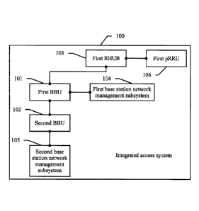
[0071] The second BBU 102 is connected to the second base station
network management
subsystem 105.
[0072] The first pRRU 106 is connected to the first data exchange unit
103.
[0073] In the integrated access system provided in this embodiment of
this application, at
least two types of BBUs are used: the first BBU 101 and the second BBU 102.
The first BBU
101 and the second BBU 102 may be connected to each other through a fiber
channel. For
example, the fiber channel may specifically include a CPRI channel and a media
access
control (Media Access Control, MAC) channel. The first BBU 101 may be
connected to the
first base station network management subsystem 104 through an operation
management
(Operate Management, OM) channel. The first base station network management
subsystem
104 is a network management subsystem used to manage the first BBU. The first
base station
18
CA 3066912 2020-01-22
85831270
network management subsystem may provide a radio frequency feeding function, a
function
of slicing a resource corresponding to the first data exchange unit and a
resource
corresponding to the first pRRU, and a function of an inter-subrack connection
between the
first BBU and the second BBU. The second BBU 102 is connected to the second
base station
network management subsystem 105 through an OM channel, and an operator may
configure
and manage a baseband resource by using the second base station network
management
subsystem 105.
[0074] In this embodiment of this application, the first BBU 101 serves
as a host BBU and
may be disposed in a building, and the second BBU 102 serves as a client BBU
and may be
disposed in a central equipment room. Therefore, a distributed design of the
host BBU and the
client BBU may be implemented. The first BBU 101 is connected to the first
base station
network management subsystem 104, and a radio frequency resource may be
configured and
managed by using the first base station network management subsystem 104. The
second
BBU 102 is connected to the second base station network management subsystem
105, so that
the second base station network management subsystem 105 may configure a
baseband
resource according to a requirement of an operator. Through the distributed
design of the host
BBU and the client BBU, decoupling inside the integrated access system may be
implemented, and operation and maintenance of an operator can be completed by
using only
the base station network management subsystem, thereby improving reliability
and
maintainability of the integrated access system.
[0075] In some embodiments of this application, for composition
structures that need to
be used by the first BBU and the second BBU according to their respective
requirements, the
first BBU may include a radio frequency board, an interface board, a main
control board, and
a direct current (Direct Current, DC); and the second BBU may include a
baseband board, a
main control board, and a DC. The interface board of the first BBU may be
separately
connected to the first data exchange unit, the baseband board of the second
BBU. The main
control board of the first BBU may be connected to the first base station
network management
subsystem. The main control board of the second BBU may be connected to the
second base
station network management subsystem. In some other embodiments of this
application, in
addition to the baseband board, the main control board, the DC, the second BBU
may include
19
CA 3066912 2020-01-22
85831270
an interface board. In this case, the interface board of the first BBU may be
connected to the
interface board of the second BBU.
[0076] It should be noted that in some embodiments of this application,
the first BBU 101
and the first data exchange unit 103 may be connected to each other through a
fiber channel.
The fiber channel may specifically include a CPRI channel and a MAC channel.
The first data
exchange unit 103 may be specifically a remote CPRI data exchange unit, which
may also be
referred to as an "RHUB" in a subsequent embodiment. The RHUB may implement
communication between the first BBU 101 and the first pRRU 106, and the first
pRRU 106
implements a radio frequency signal processing function.
[0077] In some embodiments of this application, referring to FIG. 3, the
integrated access
system 100 further includes a third BBU 107 and a third base station network
management
subsystem 108.
[0078] The first BBU 101 is connected to the third BBU 107.
[0079] The third BBU 107 is connected to the third base station network
management
subsystem 108.
[0080] The first BBU 101 and the third BBU 107 may be connected to each
other through
a fiber channel. For example, the fiber channel may specifically include a
CPRI channel and a
MAC channel. The third BBU 107 may be connected to the third base station
network
management subsystem 108 through an OM channel, and an operator may configure
and
manage a baseband resource by using the third base station network management
subsystem
108.
[0081] In the foregoing embodiment of this application, in the
integrated access system
100, the first BBU 101 is disposed as a host BBU, and both the second BBU 102
and the third
BBU 107 are disposed as client BBUs. In addition, the second BBU 102 and the
third BBU
107 are connected to respective base station network management subsystems.
For example,
the second BBU 102 is connected to the second base station network management
subsystem
105, and the third BBU 107 is connected to the third base station network
management
subsystem 108. Therefore, in a scenario in which a plurality of operators
establish a network
together and share a network resource after establishment, the different
operators may
separately use the second base station network management subsystem and the
third base
station network management subsystem, thereby implementing asset decoupling,
operation
CA 3066912 2020-01-22
85831270
and maintenance decoupling, and service activation and upgrade decoupling
between the
plurality of operators. Client BBUs included in the integrated access system
100 may be not
limited to the second BBU and the third BBU. When a plurality of client BBUs
are connected
to the first BBU (namely, the host BBU) in the integrated access system
through a fiber
channel, each client BBU may be connected to one base station network
management
subsystem. Each of the different operators may use one base station network
management
subsystem, and the operators are decoupled, so that the operators do not
interfere with each
other.
[0082] FIG 5 is a schematic diagram of system architecture deployment of
an integrated
access system according to an embodiment of this application. One host BBU and
three client
BBUs (a client BBU 1, a client BBU 2, and a client BBU 3) are disposed in the
integrated
access system. The host BBU is disposed in a building at a remote end, and the
three client
BBUs are disposed in a central equipment room at a local end. The host BBU
includes a radio
frequency board R, an interface board, a main control board, and a DC. The
interface board of
the host BBU is separately connected to baseband boards of the three client
BBUs, and the
interface board of the host BBU is further connected to an RHUB through a CPRI
channel and
a MAC channel. The RHUB is connected to a pRRU through an electrical interface
(which is
also referred to as a CPRI-E interface) of the CPRI channel or through an
electrical interface
of the MAC channel. The main control board of the host BBU is connected to an
indoor
distributed unified network management subsystem (which is abbreviated to a
BTS (R) in
FIG 5). The radio frequency board R of the host BBU is connected to a remote
radio unit
(Remote Radio Unit, RRU). For example, three RRUs are further disposed in the
integrated
access system in FIG 5. The three RRUs are respectively an RRU-A, an RRU-B,
and an
RRU-C. Each RRU supports a global system for mobile communications (Global
System for
Mobile Communication, GSM), a universal mobile telecommunications system
(Universal
Mobile Telecommunications System, UMTS), long term evolution (Long Term
Evolution,
LTE), and code division multiple access (Code Division Multiple Access, CDMA),
that is,
"G/U/L/C" shown in FIG. 5. Each client BBU includes a baseband board and a
main control
board. The baseband board of the client BBU is connected to the interface
board of the host
BBU. The main control board of the client BBU is connected to a baseband
network
management subsystem (which is abbreviated to a BTS (UL) in FIG. 5). For
example, the
21
CA 3066912 2020-01-22
85831270
main control board of the client BBU 1 is connected to a base station network
management
subsystem through an OM channel, and an operator A may configure and manage a
baseband
resource by using the base station network management subsystem. The client
BBU 2 is
connected to a base station network management subsystem through an OM
channel, and an
operator B may configure and manage a baseband resource by using the base
station network
management subsystem. The client BBU 3 is connected to a base station network
management subsystem through an OM channel, and an operator C may configure
and
manage a baseband resource by using the base station network management
subsystem. In this
embodiment of this application, a plurality of client BBUs can be converged at
a host BBU, so
that a plurality of operators access different BBUs. This resolves a problem
of operation and
maintenance decoupling between the operators, and is applicable to future
large-capacity
evolution and 5G evolution scenarios.
[0083] In some embodiments of this application, referring to FIG 5, the
integrated access
system further includes a fourth BBU 109, a second data exchange unit 110, a
fourth base
station network management subsystem 111, and a second pRRU 112.
[0084] The fourth BBU 109 is connected to the second data exchange unit
110, the fourth
BBU 109 is connected to the fourth base station network management subsystem
111, and the
fourth BBU 109 is connected to the second BBU 102.
[0085] The second pRRU 112 is connected to the second data exchange unit
110.
[0086] In the integrated access system, both the first BBU 101 and the
fourth BBU 109
may serve as host BBUs. For example, the first BBU 101 and the fourth BBU 109
may be
disposed in different buildings. The first BBU 101 and the fourth BBU 109 may
be separately
connected to the second BBU 102 through different fiber channels. The second
BBU 102 may
be disposed in a central equipment room, to support an inter-subrack
connection between a
client BBU and a plurality of host BBUs, so that one central equipment room
covers a
plurality of surrounding buildings.
[0087] It should be noted that in the foregoing embodiment of this
application, if a
plurality of operators need to access the integrated access system, each
operator can use one
client BBU and one base station network management subsystem. When there are a
plurality
of host BBUs, each host BBU can be connected to all client BBUs. For a
connection manner,
22
CA 3066912 2020-01-22
85831270
refer to a manner in which the first BBU 101 and the fourth BBU 109 are
separately
connected to the second BBU 102.
[0088] FIG 6A, FIG 6B, FIG 6C, and FIG 6D are a schematic diagram of
system
architecture deployment of another integrated access system according to an
embodiment of
this application. Three host BBUs and three client BBUs (a client BBU 1, a
client BBU 2, and
a client BBU 3) are disposed in the integrated access system. A host BBU 0 is
disposed in a
building 0 at a remote end, a host BBU 1 is disposed in a building 1 at a
remote end, and a
host BBU 2 is disposed in a building 2 at a remote end. The three client BBUs
are disposed in
a central equipment room at a local end. The host BBU disposed in the building
0 is used as
an example. The host BBU includes a radio frequency board R, an interface
board, a main
control board, and a DC. The interface board of the host BBU is separately
connected to
baseband boards of the three client BBUs, and the interface board of the host
BBU is further
connected to an RHUB through a CPRI channel and a MAC channel. The RHUB is
connected
to a pRRU through a CPRI-E interface or an electrical interface of the MAC
channel. The
.. main control board of the host BBU is connected to an indoor distributed
unified network
management subsystem (which is abbreviated to a BTS (R) in FIG 5). The radio
frequency
board R of the host BBU is connected to an RRU. For example, three RRUs are
further
disposed in the integrated access system in FIG 6. The three RRUs are
respectively an
RRU-A, an RRU-B, and an RRU-C. As shown in FIG 6, a plurality of host BBUs or
a
plurality of client BBUs may be disposed in the integrated access system.
Therefore, an
inter-subrack connection between a client BBU and a plurality of host BBUs may
be
supported, so that one central equipment room covers a plurality of
surrounding buildings.
[0089] It can be learned from the description of the composition
structure of the integrated
access system provided in the embodiments of this application that the
integrated access
system includes two types of BBUs: the first BBU and the second BBU. The first
BBU and
the second BBU are connected to communicate with each other. In addition, the
first BBU is
connected to the first base station network management subsystem, and the
second BBU is
connected to the second base station network management subsystem. Therefore,
a radio
frequency resource of the first BBU may be separately configured and managed
by using the
first base station network management subsystem, and a baseband resource of
the second
BBU may be separately configured and managed by using the second base station
network
23
CA 3066912 2020-01-22
85831270
management subsystem. In this way, a radio frequency resource and a baseband
resource can
be independently managed, and reliability and maintainability of the
integrated access system
are greatly improved.
[0090] The integrated access system provided in the embodiments of this
application is
described in the foregoing embodiments. A configuration method based on the
integrated
access system is described below. The method may be used to implement clock
configuration
in the integrated access system. A configuration method provided in an
embodiment of this
application is applicable to an integrated access system. As shown in FIG 2,
the integrated
access system includes a first BBU and a second BBU. The first BBU is
connected to the
second BBU. For example, the first BBU and the second BBU are connected to
each other
through a fiber channel. As shown in FIG 7, the configuration method provided
in this
embodiment of this application may include the following steps:
[0091] 701. The first BBU obtains first clock synchronization
information, where the first
clock synchronization information includes a clock frequency and a clock phase
of the first
BBU.
[0092] 702. The first BBU sends the first clock synchronization
information to the second
BBU.
[0093] The first BBU serves as a host BBU, and the first BBU needs to
provide a
reference clock to the second BBU. The second BBU may correct a local clock of
the second
BBU based on the reference clock provided by the first BBU, thereby
implementing
inter-subrack clock synchronization between BBUs. The first BBU may obtain the
clock
frequency and the clock phase of the first BBU from a local clock source, and
then the first
BBU sends the first clock synchronization information to the second BBU. In
addition, the
first BBU may interact with a clock server, and obtain the clock frequency and
the clock
phase from the clock server. Then the first BBU corrects the local clock
source of the first
BBU based on the clock frequency and the clock phase, for example, may perform
feedback
control by using a phase-locked loop (Phase-Locked Loop, PLL), and control a
frequency and
a phase of a clock signal in the loop by using an external reference signal
provided by the
clock server. The first BBU and the second BBU may be connected to each other
through a
fiber channel, and the fiber channel may specifically include a CPRI channel
and a MAC
channel. The first BBU may add the first clock synchronization information to
a CPRI frame,
24
CA 3066912 2020-01-22
85831270
and then send the CPRI frame to the second BBU through the CPRI channel.
Alternatively,
the first BBU may add the first clock synchronization information to a MAC
channel, and
then send the MAC frame to the second BBU through the MAC channel.
[0094] In some embodiments of this application, with reference to FIG 3,
the integrated
access system further includes a third BBU, and the third BBU is connected to
the first BBU.
In this implementation scenario, the configuration method based on the
integrated access
system may further include the following step:
[0095] Al. The first BBU sends the first clock synchronization
information to the third
BBU.
[0096] When the first BBU is connected to two client BBUs as a host BBU,
after the first
BBU obtains the first clock synchronization information, the first BBU may
separately send
the first clock synchronization information to the second BBU and the third
BBU, so that the
third BBU, as a client BBU, can also receive the first clock synchronization
information of the
first BBU. The third BBU may use the first clock synchronization information
to correct a
local clock source of the third BBU, thereby implementing inter-subrack clock
synchronization between BBUs.
[0097] It should be noted that in the foregoing embodiment of this
application, a clock
synchronization process is described from a first BBU side. It may be
understood that a
method performed by the fourth BBU is similar to the method performed by the
first BBU.
The fourth BBU may generate second clock synchronization information, and then
the fourth
BBU sends the second clock synchronization information to the second BBU. The
second
clock synchronization information includes a clock frequency and a clock phase
of the fourth
BBU.
[0098] It can be learned from the example description of a clock
configuration process
shown in FIG 7 that the first BBU may send the first clock synchronization
information to the
second BBU, so that the second BBU can configure local clock information of
the second
BBU based on the first clock synchronization information, thereby implementing
inter-subrack clock synchronization between BBUs. For example, a BBU mode is
configured.
Through an OM channel of a base station network management subsystem, the
first BBU may
be configured as a host BBU mode, and the second BBU may be configured as a
client BBU
mode. Inter-subrack convergence of a plurality of BBUs is supported, so that a
plurality of
CA 3066912 2020-01-22
85831270
operators access different BBUs, thereby resolving a problem of operation and
maintenance
decoupling between the operators, and implementing future large-capacity
evolution based on
BBU access. In addition, inter-subrack connection between a plurality of host
BBUs and a
plurality of client BBUs is supported in this embodiment of this application,
so that one
central equipment room covers a plurality of surrounding buildings.
[0099] The configuration method based on the integrated access system is
described from
a first BBU side in the foregoing embodiment, and the configuration method
based on the
integrated access system provided in the embodiments of this application is
described below
from a second BBU side. The method may be used to implement clock
configuration in the
integrated access system. A configuration method provided in an embodiment of
this
application is applicable to an integrated access system. As shown in FIG. 2,
the integrated
access system includes a first BBU and a second BBU. The first BBU is
connected to the
second BBU. For example, the first BBU and the second BBU are connected to
each other
through a fiber channel. As shown in FIG 8, the configuration method provided
in this
embodiment of this application may include the following steps.
[0100] 801. The second BBU receives first clock synchronization
information sent by the
first BBU, where the first clock synchronization information includes a clock
frequency and a
clock phase of the first BBU.
[0101] The second BBU and the first BBU are connected to each other
through a fiber
channel. The first BBU sends the first clock synchronization information to
the second BBU.
The second BBU may receive the first clock synchronization information through
the fiber
channel, and the second BBU may parse the first clock synchronization
information to obtain
the clock frequency and the clock phase of the first BBU.
[0102] 802. The second BBU configures local clock information of the
second BBU based
on the first clock synchronization information.
[0103] After the second BBU obtains the first clock synchronization
information from the
first BBU, the second BBU corrects the local clock information of the second
BBU by using
the clock frequency and the clock phase of the first BBU as a reference clock
source. For
example, the second BBU may perform feedback control by using a PLL, and
control a
frequency and a phase of a clock signal in the loop by using an external
reference signal
provided by the first BBU.
26
CA 3066912 2020-01-22
85831270
[0104] In some embodiments of this application, the integrated access
system further
includes a fourth BBU, and the fourth BBU is connected to the second BBU. A
method
performed by the fourth BBU is described in the foregoing embodiment of this
application.
The fourth BBU may generate second clock synchronization information, and then
the fourth
BBU sends the second clock synchronization information to the second BBU. The
second
clock synchronization information includes a clock frequency and a clock phase
of the fourth
BBU. In this scenario, in addition to the foregoing steps, the configuration
method provided in
this embodiment of this application includes the following step:
[0105] Bl. The second BBU receives the second clock synchronization
information sent
by the fourth BBU, where the second clock synchronization information includes
the clock
frequency and the clock phase of the fourth BBU.
[0106] In addition to receiving the first clock synchronization
information, the second
BBU receives the second clock synchronization information of the fourth BBU.
The second
BBU may parse the second clock synchronization information to obtain the clock
frequency
and the clock phase of the fourth BBU. When both the second BBU and the fourth
BBU serve
as host BBUs, the second BBU and the fourth BBU may separately send the clock
synchronization information to the second BBU serving as a client BBU, and the
second BBU
may separately obtain the clock frequency and the clock phase of the first
BBU, and the clock
frequency and the clock phase of the fourth BBU.
[0107] In the implementation scenario in which step B1 is performed, step
802 in which
the second BBU configures the local clock information of the second BBU based
on the first
clock synchronization information includes the following step:
[0108] Cl. The second BBU configures the local clock information of the
second BBU
based on the first clock synchronization information and the second clock
synchronization
information.
[0109] When the second BBU separately obtains the first clock
synchronization
information and the second clock synchronization information, the second BBU
may obtain
the clock frequency and the clock phase of the first BBU, and the clock
frequency and the
clock phase of the fourth BBU. The second BBU determines the local clock
information of
the second BBU by using the clock synchronization information of the two host
BBUs. The
second BBU may configure the local clock information in a plurality of manner.
For example,
27
CA 3066912 2020-01-22
85831270
step Cl in which the second BBU configures the local clock information of the
second BBU
based on the first clock synchronization information and the second clock
synchronization
information includes the following step:
[0110] C 1 1. The second BBU selects clock synchronization information
with higher clock
quality from the first clock synchronization information and the second clock
synchronization
information, and configures the local clock information of the second BBU
based on the clock
synchronization information with higher clock quality.
[0111] The second BBU may select the clock synchronization information
with higher
clock quality from the clock synchronization information separately sent by
the first BBU and
the fourth BBU to the second BBU, and configure the local clock information of
the second
BBU based on the clock synchronization information with higher clock quality.
Clock quality
is clock signal quality of a clock source. The clock quality may be measured
by stability of the
clock source, measured by accuracy of the clock source, or measured by
stability and
accuracy of the clock source. The clock source has two important indicators:
stability and
accuracy. Accuracy refers to a deviation from a nominal value, and stability
refers to a change
amount generated as an external factor changes. For example, higher stability
and accuracy
indicate higher clock quality of the clock source. In some embodiments of this
application,
when the second BBU configures the local clock information of the second BBU
based on the
first clock synchronization information and the second clock synchronization
information, the
foregoing example description is not intended for limitation, the second BBU
may select
clock synchronization information with higher stability from the first clock
synchronization
information and the second clock synchronization information, and configure
the local clock
information of the second BBU based on the clock synchronization information
with higher
stability. The clock synchronization information with higher stability is
selected as the local
clock information of the second BBU, so that clock stability of the second BBU
may be
ensured.
[0112] It can be learned from the example description of a clock
configuration process
shown in FIG 8 that the first BBU may send the first clock synchronization
information to the
second BBU, so that the second BBU can configure the local clock information
of the second
BBU based on the first clock synchronization information, thereby implementing
inter-subrack clock synchronization between BBUs.
28
CA 3066912 2020-01-22
85831270
[0113] The clock configuration processes shown in FIG 7 and FIG. 8 are
described below
by using an example. Referring to FIG 4, clock synchronization between a host
BBU and a
client BBU is used as an example for description. In this embodiment of this
application,
inter-subrack clock soft synchronization based on panel CPRI interconnection
may be
implemented. To be specific, the host BBU transfers clock frequency and phase
information
of the host BBU to the client BBU through an inter-subrack fiber by using a
CPRI frame or a
MAC frame. A mode is first selected for a BBU. A mode of the first BBU is
configured as a
host (Host) BBU mode, and a mode of the second BBU is configured as a client
(Client) BBU
mode. In the integrated access system provided in this embodiment of this
application, a BBU
may be configured as a host BBU or a client BBU through an OM channel of a
base station
network management subsystem.
[0114] An indoor distributed unified network management subsystem is
used to configure
the host BBU. The host BBU obtains a clock from a local clock source of the
host BBU, and
broadcasts clock synchronization information to other client BBUs through an
interconnection
.. fiber (namely, a CPRI channel or a MAC channel). When a BBU is configured
as a client
BBU, the client BBU recovers a clock from an interconnection fiber (namely, a
CPRI channel
or a MAC channel). The client BBU uses the recovered clock as a reference
clock source of
the client BBU, to implement inter-subrack clock synchronization.
[0115] The integrated access system provided in the embodiments of this
application is
described in the foregoing embodiments. A configuration method based on the
integrated
access system is described below. The method may be used to establish an upper-
layer
communication channel in the integrated access system. In the embodiments of
this
application, an upper-layer communication channel may be automatically
established between
a host BBU and a client BBU without manual configuration, thereby reducing
manual costs
and decreasing an error probability. A configuration method provided in an
embodiment of
this application is applicable to an integrated access system. As shown in FIG
2, the
integrated access system includes a first BBU and a second BBU. The first BBU
is connected
to the second BBU. For example, the first BBU and the second BBU are connected
to each
other through a fiber channel. As shown in FIG. 9, the configuration method
provided in this
embodiment of this application may include the following steps.
29
CA 3066912 2020-01-22
85831270
[0116] 901. The first BBU updates a first line rate, and sends a data
frame to the second
BBU at an updated first line rate after each update.
[0117] A line rate used by the first BBU is defined as the "first line
rate", and a line rate
used by the second BBU is defined as a "second line rate". The line rate is a
line rate of a
physical layer channel. The first BBU constantly updates the first line rate,
that is, the first
BBU updates a rate value of the first line rate, and sends a data frame to the
second BBU at an
updated first line rate after each update. Similarly, the second BBU
constantly updates the
second line rate, that is, the second BBU updates a rate value of the second
line rate, and after
each update, sends an updated data frame that is based on the second line rate
to the first
BBU.
[0118] In some embodiments of this application, step 901 in which the
first BBU updates
the first line rate includes the following step:
[0119] Dl. The first BBU updates the first line rate based on a first
period, where the first
period and a second period are different periods, and the second period is a
period based on
which the second BBU updates the second line rate.
[0120] Both the first BBU and the second BBU update respective line rate
values based
on respective periods, and the first period and the second period are
different periods.
Therefore, there is necessarily a longer period and a shorter period in the
first period and the
second period. The first BBU and the second BBU periodically update respective
line rates, so
as to attempt blind line rate matching between the first BBU and the second
BBU, thereby
implementing line rate auto-negotiation without occupying manual resources to
perform
manual configuration.
[0121] 902. The first BBU receives a data frame that is sent by the
second BBU at an
updated second line rate after each time the second BBU updates the second
line rate.
[0122] After each update, the second BBU sends an updated data frame that
is based on
the second line rate to the first BBU. Therefore, the second BBU constantly
sends a data
frame that is based on the second line rate to the first BBU through the fiber
channel, and the
first BBU receives the data frame that is based on the second line rate and
that is constantly
sent by the second BBU. The first BBU needs to determine whether the sent
first line rate is
equal to the received second line rate. If the two line rates are equal, a
subsequent step 903 is
triggered; or if the two line rates are unequal, step 901 and step 902
continue to be performed.
CA 3066912 2020-01-22
85831270
[0123] 903. When the first line rate is equal to the second line rate,
the first BBU sends
networking relationship information of the first BBU to the second BBU at the
first line rate,
and receives networking relationship information of the second BBU that is
sent by the
second BBU at the second line rate.
[0124] When the first line rate sent by the first BBU is equal to the
received second line
rate, it indicates that rate negotiation between the first BBU and the second
BBU is completed.
In this case, the first BBU may send the networking relationship information
of the first BBU
to the second BBU at the first line rate, and receive the networking
relationship information of
the second BBU that is sent by the second BBU at the second line rate. The
networking
relationship information of the first BBU is a quantity of BBUs connected to
the first BBU,
and a port on an interface board connected to the first BBU. The networking
relationship
information of the second BBU is a quantity of BBUs connected to the second
BBU, and a
port on a baseband board or an interface board connected to the second BBU.
The first BBU
and the second BBU exchange the respective networking relationship
information, so that the
first BBU and the second BBU each can generate a network topology diagram
based on the
networking relationship information of the BBU. An inter-subrack connection
relationship
between a plurality of BBUs may be conveniently obtained by using the network
topology
diagram.
[0125] In some embodiments of this application, when the first line rate
is equal to the
second line rate, in addition to step 903, the method provided in this
embodiment of this
application may include the following steps:
[0126] El. The first BBU sends line rate capability information of the
first BBU to the
second BBU at the first line rate.
[0127] E2. The first BBU receives line rate capability information of
the second BBU that
.. is sent by the second BBU at the second line rate.
[0128] E3. The first BBU determines, based on the line rate capability
information of the
first BBU and the line rate capability information of the second BBU, a line
rate used for
performing physical layer communication between the first BBU and the second
BBU.
[0129] Line rate capability information is a maximum transmission
capability of a BBU
on a physical layer channel. The first BBU and the second BBU exchange the
respective line
rate capability information, and then determine, based on the line rate
capability information
31
CA 3066912 2020-01-22
85831270
of the first BBU and the line rate capability information of the second BBU,
the line rate used
for performing physical layer communication between the first BBU and the
second BBU. For
example, a maximum line rate in an intersection set of the line rate
capability information of
the first BBU and the line rate capability information of the second BBU may
be selected as
the line rate used for performing physical layer communication between the
first BBU and the
second BBU, so as to implement line rate auto-negotiation without occupying
manual
resources to perform manual configuration.
[0130] 904. The first BBU allocates a communication address to the
second BBU based
on the networking relationship information of the second BBU, and sends a
communication
address of the first BBU to the second BBU.
[0131] In this embodiment of this application, after the first BBU and
the second BBU
exchange the respective networking relationship information, the first BBU
allocates a
communication address to the second BBU based on the networking relationship
information
of the second BBU, and sends the communication address of the first BBU to the
second BBU,
so that the second BBU can obtain the communication address of the first BBU.
A
communication address may be a location identifier of a location of a BBU.
[0132] 905. The first BBU establishes a bidirectional upper-layer
communication channel
with the second BBU based on the communication address of the second BBU.
[0133] The first BBU allocates the communication address to the second
BBU, the first
BBU may obtain the communication address of the second BBU, and the second BBU
may
also obtain the communication address of the first BBU, so that the
bidirectional upper-layer
communication channel may be established between the two BBUs. The upper-layer
communication channel may be used for mutual communication between the first
BBU and
the second BBU. For example, the first BBU allocates a resource to the second
BBU based on
the upper-layer communication channel.
[0134] It can be learned from the example description of an upper-layer
communication
channel establishment process shown in FIG 9 that the first BBU and the second
BBU may
perform line rate auto-negotiation. The first BBU allocates the communication
address to the
second BBU, and the second BBU may obtain the communication address of the
first BBU.
The first BBU establishes the bidirectional upper-layer communication channel
with the
second BBU based on the communication address of the second BBU. Through line
rate
32
CA 3066912 2020-01-22
85831270
auto-negotiation, networking relationship information exchange, and
communication address
allocation, the upper-layer communication channel may be automatically
established between
the first BBU and the second BBU without manual configuration, thereby
reducing manual
costs and decreasing an error probability. For example, an upper-layer
communication channel
is automatically established between a host BBU and a client BBU, thereby
reducing a
configuration workload of service personnel and complexity of site setup.
[0135] The configuration method based on the integrated access system is
described from
a first BBU side in the foregoing embodiment, and the configuration method
based on the
integrated access system is described below from a second BBU side. The method
may be
used to establish an upper-layer communication channel in the integrated
access system. In the
embodiments of this application, an upper-layer communication channel may be
automatically
established between a host BBU and a client BBU without manual configuration,
thereby
reducing manual costs and decreasing an error probability. A configuration
method provided
in an embodiment of this application is applicable to an integrated access
system. As shown in
FIG 2, the integrated access system includes a first BBU and a second BBU. The
first BBU is
connected to the second BBU. For example, the first BBU and the second BBU are
connected
to each other through a fiber channel. As shown in FIG. 10, the configuration
method provided
in this embodiment of this application may include the following steps.
[0136] 1001. The second BBU updates a second line rate, and sends a data
frame to the
first BBU at an updated second line rate after each update.
[0137] A line rate used by the first BBU is defined as a "first line
rate", and a line rate
used by the second BBU is defined as the "second line rate". The line rate is
a line rate of a
physical layer channel. The first BBU constantly updates the first line rate,
that is, the first
BBU updates a rate value of the first line rate, and sends a data frame to the
second BBU at an
updated first line rate after each update. Similarly, the second BBU
constantly updates the
second line rate, that is, the second BBU updates a rate value of the second
line rate, and after
each update, sends an updated data frame that is based on the second line rate
to the first
BBU.
[0138] In some embodiments of this application, step 1001 in which the
second BBU
updates the second line rate includes the following step:
33
CA 3066912 2020-01-22
85831270
[0139] Fl. The second BBU updates the second line rate based on a second
period, where
the second period and a first period are different periods, and the first
period is a period based
on which the first BBU updates the first line rate.
[0140] Both the first BBU and the second BBU update respective line rate
values based
on respective periods, and the first period and the second period are
different periods.
Therefore, there is necessarily a longer period and a shorter period in the
first period and the
second period. The first BBU and the second BBU periodically update respective
line rates, so
as to attempt blind line rate matching between the first BBU and the second
BBU, thereby
implementing line rate auto-negotiation without occupying manual resources to
perform
manual configuration.
[0141] 1002. The second BBU receives a data frame that is sent by the
first BBU at an
updated first line rate after each time the first BBU updates the first line
rate.
[0142] The first BBU sends a data frame to the second BBU at an updated
first line rate
after each update. Therefore, the first BBU constantly sends a data frame that
is based on the
first line rate to the second BBU through the fiber channel, and the second
BBU receives the
data frame that is based on the first line rate and that is constantly sent by
the first BBU. The
second BBU needs to determine whether the sent second line rate is equal to
the received first
line rate. If the two line rates are equal, a subsequent step 1003 is
triggered; or if the two line
rates are unequal, step 1001 and step 1002 continue to be performed.
[0143] 1003. When the second line rate is equal to the first line rate, the
second BBU
sends networking relationship information of the second BBU to the first BBU
at the second
line rate, and receives networking relationship information of the first BBU
that is sent by the
first BBU at the first line rate.
[0144] When the second line rate sent by the second BBU is equal to the
received first
line rate, it indicates that rate negotiation between the first BBU and the
second BBU is
completed. In this case, the second BBU may send the networking relationship
information of
the second BBU to the first BBU at the second line rate, and receive the
networking
relationship information of the first BBU that is sent by the first BBU at the
first line rate. The
networking relationship information of the first BBU is a quantity of BBUs
connected to the
first BBU, and a port on an interface board connected to the first BBU. The
networking
relationship information of the second BBU is a quantity of BBUs connected to
the second
34
CA 3066912 2020-01-22
85831270
BBU, and a port on a baseband board or an interface board connected to the
second BBU. The
first BBU and the second BBU exchange the respective networking relationship
information,
so that the first BBU and the second BBU each can generate a network topology
diagram
based on the networking relationship information of the BBU. An inter-subrack
connection
relationship between a plurality of BBUs may be conveniently obtained by using
the network
topology diagram.
[0145] In some embodiments of this application, when the first line rate
is equal to the
second line rate, in addition to step 1003, the method provided in this
embodiment of this
application may include the following steps:
[0146] G1 . The second BBU sends line rate capability information of the
second BBU to
the first BBU at the second rate.
[0147] G2. The second BBU receives line rate capability information of
the first BBU that
is sent by the first BBU at the first line rate.
[0148] G3. The second BBU determines, based on the line rate capability
information of
the second BBU and the line rate capability information of the first BBU, a
line rate used for
performing physical layer communication between the first BBU and the second
BBU.
[0149] Line rate capability information is a maximum transmission
capability of a BBU
on a physical layer channel. The first BBU and the second BBU exchange the
respective line
rate capability information, and then determine, based on the line rate
capability information
of the first BBU and the line rate capability information of the second BBU,
the line rate used
for performing physical layer communication between the first BBU and the
second BBU. For
example, a maximum line rate in an intersection set of the line rate
capability information of
the first BBU and the line rate capability information of the second BBU may
be selected as
the line rate used for performing physical layer communication between the
first BBU and the
second BBU, so as to implement line rate auto-negotiation without occupying
manual
resources to perform manual configuration.
[0150] 1004. The second BBU obtains a communication address of the first
BBU.
[0151] In this embodiment of this application, after the first BBU and
the second BBU
exchange the respective networking relationship information, the first BBU
allocates a
communication address to the second BBU based on the networking relationship
information
of the second BBU, and sends the communication address of the first BBU to the
second BBU,
CA 3066912 2020-01-22
85831270
so that the second BBU can obtain the communication address of the first BBU.
A
communication address may be a location identifier of a location of a BBU.
[0152] 1005. The second BBU establishes a bidirectional upper-layer
communication
channel with the first BBU based on the communication address of the first
1313U.
[0153] The first BBU allocates the communication address to the second BBU,
the first
BBU may obtain the communication address of the second BBU, and the second BBU
may
also obtain the communication address of the first BBU, so that the
bidirectional upper-layer
communication channel may be established between the two BBUs. The upper-layer
communication channel may be used for mutual communication between the first
BBU and
the second BBU. For example, the first BBU allocates a resource to the second
BBU based on
the upper-layer communication channel.
[0154] It can be learned from the example description of an upper-layer
communication
channel establishment process shown in FIG 10 that the first BBU and the
second BBU may
perform line rate auto-negotiation. The first BBU allocates the communication
address to the
second BBU, and the second BBU may obtain the communication address of the
first BBU.
The first BBU establishes the bidirectional upper-layer communication channel
with the
second BBU based on the communication address of the second BBU. Through line
rate
auto-negotiation, networking relationship information exchange, and
communication address
allocation, the upper-layer communication channel may be automatically
established between
the first BBU and the second BBU without manual configuration, thereby
reducing manual
costs and decreasing an error probability.
[0155] The upper-layer communication channel establishment processes
shown in FIG 9
and FIG 10 are described below by using an example. FIG 11 shows a process of
automatically establishing an upper-layer communication channel between a host
BBU and a
client BBU. A port mode of the host BBU is set to a host BBU mode, and a port
mode of the
client BBU is set to a client BBU mode. For example, a CPRI channel is used
between the
host BBU and the client BBU. The host BBU and the client BBU switch line rates
of the
CPRI channel based on different periods, to achieve line rate auto-
negotiation, so that a line
rate does not need to be configured, thereby reducing manual costs and
decreasing an error
probability. The host BBU and the client BBU exchanges networking relationship
information
by using a CPRI Li control word, to implement autodiscovery of an intemet
topology. The
36
CA 3066912 2020-01-22
85831270
host BBU allocates a communication address to the client BBU, and the two
parties establish
a bidirectional upper-layer communication channel on the discovered CPRI
channel based on
the given communication address, and a client interface channel does not need
to be
configured.
[0156] The integrated access system provided in the embodiments of this
application is
described in the foregoing embodiments. A configuration method based on the
integrated
access system is described below. The method may be used to implement resource
configuration in the integrated access system. In the embodiments of this
application, a host
BBU may allocate a resource to a client BBU. A configuration method provided
in an
embodiment of this application is applicable to an integrated access system.
As shown in FIG.
2, the integrated access system includes a first BBU, a second BBU, a first
data exchange unit,
a second base station network management subsystem, and a first pRRU. The
first BBU is
separately connected to the second BBU and the first data exchange unit, the
first data
exchange unit is connected to the first pRRU, and the second BBU is connected
to the second
base station network management subsystem. As shown in FIG. 12, the
configuration method
provided in this embodiment of this application may include the following
steps.
[0157] 1201. The first BBU performs slicing processing on a resource
corresponding to
the first data exchange unit and a resource corresponding to the first pRRU,
to obtain a
plurality of sector device group object resources.
[0158] The first BBU is responsible for managing physical shared devices
such as a data
exchange unit (namely, an RHUB) and a pRRU. The first BBU may perform slicing
processing on the resource corresponding to the first pRRU and the resource
corresponding to
the RHUB. For example, the first BBU virtualizes the resource corresponding to
the first
pRRU and the resource corresponding to the RHUB, to abstract the resources as
resource
objects. Then the first BBU performs slicing processing on the resource
objects, and defines
slice resources obtained after slicing processing as a plurality of sector
device object resources.
The sector device object resources are resource objects used for sending a
same carrier signal
through broadcast by one or more pRRUs in an indoor distributed integrated
access system
during downlink transmission, or resource objects of a same carrier signal
that are formed
through radio frequency combination during uplink transmission. For example,
the first BBU
serves as a host BBU, and is configured to manage a resource corresponding to
an RHUB and
37
CA 3066912 2020-01-22
85831270
a resource corresponding to a pRRU. The first BBU slices the resource
corresponding to the
RHUB into three radio frequency combination resource slices, and the first BBU
slices a
carrier resource corresponding to the pRRU into three carrier resource slices.
In this case, a
radio frequency combination resource slice of one RHUB and corresponding
carrier resource
slices in one or more pRRUs may be combined into one sector device group
object resource.
In the example scenario, the first BBU may generate three sector device group
object
resources.
[0159] In some embodiments of this application, the resource
corresponding to the first
data exchange unit includes a radio frequency combination cell capability
resource and a
transmission channel bandwidth resource, and the resource corresponding to the
first pRRU
includes a radio frequency resource. If the first BBU and the first data
exchange unit are
connected to each other through a CPRI channel, the transmission channel
bandwidth resource
is specifically a CPRI bandwidth resource. The radio frequency resource may
include a
network standard, a frequency band, transmit power, and a bandwidth. The radio
frequency
combination cell capability resource is a resource such as a quantity of radio
frequency
combination cells.
[0160] 1202. The first BBU selects a first sector device group object
resource from the
plurality of sector device group object resources based on a resource
configuration request of
the second base station network management subsystem.
[0161] The first BBU is connected to the second BBU, and the second BBU is
connected
to the second base station network management subsystem. The first BBU may
obtain the
resource configuration request of the second base station network management
subsystem by
using the second BBU, and then the first BBU selects, for the second base
station network
management subsystem, the first sector device group object resource from the
plurality of
sector device group object resources. For example, the first BBU performs
unified resource
allocation on a first BBU side based on actual situations of operators. For
example, an
operator uses an LTE standard and a 20M bandwidth, and needs to establish two
20M physical
cells. In this case, the first BBU may allocate a sector device group object
resource to the
operator based on a resource configuration of the operator.
[0162] 1203. The first BBU notifies the second BBU of the first sector
device group
object resource.
38
CA 3066912 2020-01-22
85831270
[0163] In this embodiment of this application, after the first BBU
selects the first sector
device group object resource in step 1202, the first BBU notifies the second
BBU of the first
sector device group object resource. For example, a fiber channel is used
between the first
BBU and the second BBU, and the first BBU may notify the second BBU of the
first sector
device group object resource through the fiber channel. The second BBU invokes
a resource
allocated on the first BBU side and performs binding, for example, binds a
radio frequency
resource allocated on the first BBU side to a baseband resource on a second
BBU side, to
activate a corresponding BBU cell and a corresponding service. The first BBU
performs
slicing processing, so that operator devices can independently invoke common
resources such
as an RHUB and a pRRU.
[0164] In some embodiments of this application, in addition to the
foregoing steps, the
integrated access system provided in this embodiment of this application
includes a third BBU
and a third base station network management subsystem. As shown in FIG 5, the
first BBU is
connected to the third BBU, the third BBU is connected to the third base
station network
management subsystem, and the method provided in this embodiment of this
application
further includes the following steps:
[0165] Hi. The first BBU selects a second sector device group object
resource from the
plurality of sector device group object resources based on a resource
configuration request of
the third base station network management subsystem.
[0166] H2. The first BBU notifies the third BBU of the second sector device
group object
resource.
[0167] If the first BBU is connected to the second BBU and the third BBU
through a fiber
channel, the first BBU may further allocate the second sector device group
object resource to
the third base station network management subsystem based on the resource
configuration
request of the third base station network management subsystem, so that
operator devices can
independently invoke common resources such as an RHUB and a pRRU.
[0168] It can be learned from the example description of a resource
configuration process
shown in FIG 12 that the first BBU performs slicing processing on the resource
corresponding to the first data exchange unit and the resource corresponding
to the first pRRU,
to obtain the plurality of sector device group object resources. The first BBU
allocates the first
sector device group object resource to the second base station network
management
39
CA 3066912 2020-01-22
85831270
subsystem based on the resource configuration request of the second base
station network
management subsystem, so that operator devices can independently invoke common
resources
such as an RI-TUB and a pRRU.
[0169] The configuration method based on the integrated access system is
described from
a first BBU side in the foregoing embodiment, and the configuration method is
described
below from a second BBU side by using an example. The method may be used to
implement
resource configuration in the integrated access system. In the embodiments of
this application,
a host BBU may allocate a resource to a client BBU. A configuration method
provided in an
embodiment of this application is applicable to an integrated access system.
As shown in
FIG 2, the integrated access system includes a first BBU, a second BBU, a
first data exchange
unit, a second base station network management subsystem, and a first pRRU.
The first BBU
is separately connected to the second BBU and the first data exchange unit,
the first data
exchange unit is connected to the first pRRU, and the second BBU is connected
to the second
base station network management subsystem. As shown in FIG 13, the
configuration method
provided in this embodiment of this application may include the following
steps:
[0170] 1301. The second BBU obtains a first sector device group object
resource notified
by the first BBU.
[0171] 1302. The second BBU binds the first sector device group object
resource to a
baseband resource of the second BBU, and activates a physical cell
corresponding to the first
sector device group object resource.
[0172] A fiber channel is used between the first BBU and the second BBU,
and the first
BBU may notify the second BBU of the first sector device group object resource
through the
fiber channel. The second BBU invokes a resource allocated on a first BBU side
and performs
binding, for example, binds a radio frequency resource allocated on the first
BBU side to a
baseband resource on a second BBU side, to activate a corresponding BBU cell
and a
corresponding service. The baseband resource herein is a physical cell
resource on a base
station side. The second BBU may use a corresponding sector device group
object resource
based on allocation of the first BBU, so that operator devices can
independently invoke
common resources such as an RHUB and a pRRU.
[0173] It can be learned from the example description of a resource
configuration process
shown in FIG. 13 that the second BBU obtains the first sector device group
object resource
CA 3066912 2020-01-22
85831270
notified by the first BBU, and the second BBU binds the first sector device
group object
resource to the baseband resource of the second BBU, and activates the
physical cell
corresponding to the first sector device group object resource, so that
operator devices can
independently invoke common resources such as an RHUB and a pRRU.
[0174] The resource allocation processes shown in FIG. 12 and FIG 13 are
described
below by using an example. FIG 14 shows an example description of a resource
allocation
process between a host BBU and a client BBU. The host BBU is connected to a
base station
network management subsystem and an RHUB, and the RHUB is connected to a pRRU.
The
host BBU is connected to three client BBUs, which are respectively a client
BBU A, a client
BBU B, and a client BBU C. Each client BBU is connected to one base station
network
management subsystem. The host BBU is configured to manage the physical
devices: the
RHUB and the pRRU. The host BBU first performs slicing processing on a
resource
corresponding to the RHUB and a resource corresponding to the pRRU, to obtain
a sector
device group object resource A (which is referred to as a resource A for short
in FIG 14), a
sector device group object resource B (which is referred to as a resource B
for short in
FIG 14), and a sector device group object resource (which is referred to as a
resource C for
short in FIG. 14). The host BBU may allocate the resource A to the client BBU
A for use.
Therefore, the client BBU A may invoke the resource A, and then manage a BBU
service
based on the resource A.
[0175] The integrated access system provided in the embodiments of this
application may
support resource pooling and virtualization management on an RHUB and a pRRU
connected
to a host BBU. The host BBU is responsible for managing the physical devices:
the RHUB
and the pRRU, and virtualizing and slicing resource objects of the pRRU and
the RHUB. The
host BBU performs unified resource allocation on a client BBU side based on
resource
requests of operators. On the client BBU side, each client BBU invokes a
resource allocated
on the host BBU side and performs binding, for example, binds a radio
frequency resource
allocated on the host BBU side to a baseband resource on the client BBU side,
to activate a
corresponding BBU cell and a corresponding service. Through virtualization and
slicing,
operator devices can independently invoke common resources such as an RHUB and
a pRRU.
[0176] A resource slicing procedure is described below by using an example.
A host
construction party (a host BBU) first collects network construction
requirements of operators
41
CA 3066912 2020-01-22
85831270
for a target site. Then the host BBU outputs a resource allocation result
based on the network
construction requirements of the operators and an actual site investigation.
For example,
physical device information such as quantities of pRRUs, RHUBs, and host BBUs
are first
collected. In addition, a specific pRRU physical position and unified planned
resource
requirements in network construction requirements of operators corresponding
to each
physical position are collected, for example, requirements for a network
standard, a frequency,
a bandwidth, transmit power, and a radio frequency combination cell. The host
BBU is
configured based on a resource design and plan. Resource slicing is performed
for different
operators by using a sector device group object (including a standard, a
frequency, a
bandwidth, transmit power, and pRRU radio frequency combination information).
Each client
BBU invokes a slice resource (namely, a sector device group object resource)
allocated by the
host BBU, and binds the sector device group object resource to a baseband
resource of the
client BBU, to establish and activate a corresponding physical cell, and
activate a service.
[0177] Referring to FIG 15, a process in which a host BBU allocates a
resource to a client
BBU is described below by using an example. The host BBU first sends resource
states of a
pRRU and an RHUB to the client BBU. The client BBU sends a resource request to
the host
BBU, and the host BBU performs resource quota control. The host BBU allocates
a resource
to the client BBU, and the client BBU uses the resource allocated by the host
BBU to perform
a resource binding operation. For details, refer to the description of
resource binding in the
foregoing embodiment. The host BBU allocates, based on a resource
authorization
configuration for a client BBU through an upper-layer communication channel, a
resource
corresponding to the pRRU and a resource corresponding to the RHUB that are
available to an
authorized client BBU. For example, the host BBU allocates a radio frequency
resource and a
network resource to the client BBU. The network resource includes a CPRI
bandwidth
capability, a radio frequency combination cell capability, and the like. In
this embodiment of
this application, a BBU can flexibly use a resource based on a service
expansion requirement.
The host BBU configures and limits a maximum quantity of resources used by the
client BBU,
to implement shared resource quota management and control.
[0178] It can be learned from the example description of the resource
configuration
process that in this embodiment of this application, a problem of operation
and maintenance
decoupling between a host construction party (a host BBU is configured by
using a base
42
CA 3066912 2020-01-22
85831270
station network management subsystem of the host BBU) and an operator (a
client BBU is
configured by using a base station network management subsystem of the client
BBU), and
operation and maintenance decoupling between operators may be resolved. The
host
construction party is mainly responsible for establishment of an indoor
hardware network,
.. focuses on establishment of a pRRU, an RHUB, and the host BBU, and does not
participate in
a specific service of a baseband cell. Operators separately manage respective
client BBUs, and
focus on respective BBU services, and operation and maintenance of the
operators. Therefore,
in this embodiment of this application, unified establishment, operation and
maintenance of
indoor distributed common systems are implemented, different service solutions
provided by
.. operators are decoupled, and service development of the operators is also
decoupled. To be
specific, an independent BBU version, cell, service characteristic, and the
like are activated.
[0179] It should be noted that for brief description, the foregoing
method embodiments
are described as a series of actions. However, a person skilled in the art
should appreciate that
this application is not limited to the described order of the actions, because
according to this
.. application, some steps may be performed in another order or
simultaneously. It should be
further appreciated by a person skilled in the art that all the embodiments
described in this
specification are example embodiments, and the actions and modules are not
necessarily
required by this application.
[0180] To better implement the solutions of the embodiments of this
application, related
apparatuses for implementing the solutions are further provided below.
[0181] Referring to FIG 16, an embodiment of this application provides a
baseband unit
BBU. The BBU is specifically a first BBU, and the first BBU belongs to an
integrated access
system. The integrated access system further includes a second BBU, and the
first BBU is
connected to the second BBU. The first BBU 1600 includes:
an obtaining module 1601, configured to obtain first clock synchronization
information, where the first clock synchronization information includes a
clock frequency and
a clock phase of the first BBU; and
a sending module 1602, configured to send the first clock synchronization
information to the second BBU.
[0182] In some embodiments of this application, the integrated access
system further
includes a third BBU, the third BBU is connected to the first BBU, and the
sending module
43
CA 3066912 2020-01-22
85831270
1602 is further configured to send the first clock synchronization information
to the third
BBU.
[0183] Referring to FIG 17, an embodiment of this application provides a
baseband unit
BBU. The BBU is specifically a second BBU 1700, and the second BBU belongs to
an
integrated access system. The integrated access system further includes a
first BBU, and the
first BBU is connected to the second BBU. The second BBU 1700 includes:
a receiving module 1701, configured to receive first clock synchronization
information sent by the first BBU, where the first clock synchronization
information includes
a clock frequency and a clock phase of the first BBU; and
a configuration module 1702, configured to configure local clock information
of
the second BBU based on the first clock synchronization information.
[0184] In some embodiments of this application, the integrated access
system further
includes a fourth BBU, the fourth BBU is connected to the second BBU, and the
receiving
module 1701 is further configured to receive second clock synchronization
information sent
by the fourth BBU. The second clock synchronization information includes a
clock frequency
and a clock phase of the fourth BBU.
[0185] The configuration module 1702 is specifically configured to
configure the local
clock information of the second BBU based on the first clock synchronization
information and
the second clock synchronization information.
[0186] Further, in some embodiments of this application, the configuration
module 1702
is specifically configured to: select clock synchronization information with
higher clock
quality from the first clock synchronization information and the second clock
synchronization
information, and configure the local clock information of the second BBU based
on the clock
synchronization information with higher clock quality.
[0187] Referring to FIG 18-a, an embodiment of this application provides a
baseband unit
BBU. The BBU is specifically a first BBU 1800, and the first BBU belongs to an
integrated
access system. The integrated access system further includes a second BBU, and
the first
BBU is connected to the second BBU. The first BBU 1800 includes:
a line rate update module 1801, configured to: update a first line rate, and
send a
data frame to the second BBU at an updated first line rate after each update;
44
CA 3066912 2020-01-22
85831270
a receiving module 1802, configured to receive a data frame that is sent by
the
second BBU at an updated second line rate after each time the second BBU
updates a second
line rate;
a sending module 1803, configured to: when the first line rate is equal to the
.. second line rate, send networking relationship information of the first BBU
to the second
BBU at the first line rate, and receive networking relationship information of
the second BBU
that is sent by the second BBU at the second line rate;
an address allocation module 1804, configured to: allocate a communication
address to the second BBU based on the networking relationship information of
the second
BBU, and send a communication address of the first BBU to the second BBU; and
a channel establishment module 1805, configured to establish a bidirectional
upper-layer communication channel with the second BBU based on the
communication
address of the second BBU.
[0188] In some embodiments of this application, as shown in FIG. 18-b,
when the first line
rate is equal to the second line rate, the first BBU 1800 further includes a
line rate determining
module 1806.
[0189] The sending module 1803 is further configured to send line rate
capability
information of the first BBU to the second BBU at the first line rate.
[0190] The receiving module 1802 is further configured to receive line
rate capability
information of the second BBU that is sent by the second BBU at the second
line rate.
[0191] The line rate determining module 1806 is configured to determine,
based on the
line rate capability information of the first BBU and the line rate capability
information of the
second BBU, a line rate used for performing physical layer communication
between the first
BBU and the second BBU.
[0192] Referring to FIG 19-a, an embodiment of this application provides a
baseband unit
BBU. The BBU is specifically a second BBU 1900, and the second BBU belongs to
an
integrated access system. The integrated access system further includes a
first BBU, and the
first BBU is connected to the second BBU. The second BBU 1900 includes:
a line rate update module 1901, configured to: update a second line rate, and
send a
data frame to the first BBU at an updated second line rate after each update;
CA 3066912 2020-01-22
85831270
a receiving module 1902, configured to receive a data frame that is sent by
the first
BBU at an updated first line rate after each time the first BBU updates a
first line rate;
a sending module 1903, configured to: when the second line rate is equal to
the
first line rate, send, by the second BBU, networking relationship information
of the second
BBU to the first BBU at the second line rate, and receive networking
relationship information
of the first BBU that is sent by the first BBU at the first line rate;
an address obtaining module 1904, configured to obtain a communication address
of the first BBU; and
a channel establishment module 1905, configured to establish a bidirectional
upper-layer communication channel with the first BBU based on the
communication address
of the first BBU.
[0193] In some embodiments of this application, as shown in FIG. 19-b,
when the second
line rate is equal to the first line rate, the second BBU 1900 further
includes a line rate
determining module 1906.
[0194] The sending module 1903 is further configured to send line rate
capability
information of the second BBU to the first BBU at the second rate.
[0195] The receiving module 1902 is further configured to receive line
rate capability
information of the first BBU that is sent by the first BBU at the first line
rate.
[0196] The line rate determining module 1906 is configured to determine,
based on the
line rate capability information of the second BBU and the line rate
capability information of
the first BBU, a line rate used for performing physical layer communication
between the first
BBU and the second BBU.
[0197] Referring to FIG 20, an embodiment of this application provides a
baseband unit
BBU. The BBU is specifically a first BBU 2000, and the first BBU belongs to an
integrated
access system. The integrated access system further includes a second BBU, a
first data
exchange unit, a second base station network management subsystem, and a first
pico remote
radio unit pRRU. The first BBU is separately connected to the second BBU and
the first data
exchange unit, the first data exchange unit is connected to the first pRRU,
and the second
BBU is connected to the second base station network management subsystem. The
first BBU
2000 includes:
46
CA 3066912 2020-01-22
85831270
a slicing module 2001, configured to perform slicing processing on a resource
corresponding to the first data exchange unit and a resource corresponding to
the first pRRU,
to obtain a plurality of sector device group object resources;
a resource allocation module 2002, configured to select a first sector device
group
object resource from the plurality of sector device group object resources
based on a resource
configuration request of the second base station network management subsystem;
and
a notification module 2003, configured to notify the second BBU of the first
sector
device group object resource.
[0198] In some embodiments of this application, the integrated access
system further
includes a third BBU and a third base station network management subsystem.
The first BBU
is connected to the third BBU, and the third BBU is connected to the third
base station
network management subsystem.
[0199] The resource allocation module 2002 is further configured to
select a second sector
device group object resource from the plurality of sector device group object
resources based
on a resource configuration request of the third base station network
management subsystem.
[0200] The notification module 2003 is further configured to notify the
third BBU of the
second sector device group object resource.
[0201] Referring to FIG 21, an embodiment of this application provides a
baseband unit
BBU. The BBU is specifically a second BBU 2100, and the second BBU belongs to
an
integrated access system. The integrated access system further includes a
first BBU, a second
BBU, a first data exchange unit, a second base station network management
subsystem, and a
first pico remote radio unit pRRU. The first BBU is separately connected to
the second BBU
and the first data exchange unit, the first data exchange unit is connected to
the first pRRU,
and the second BBU is connected to the second base station network management
subsystem.
The second BBU 2100 includes:
a resource obtaining module 2101, configured to obtain a first sector device
group
object resource notified by the first BBU; and
a resource use module 2102, configured to: bind the first sector device group
object resource to a baseband resource of the second BBU, and activate a
physical cell
corresponding to the first sector device group object resource.
47
CA 3066912 2020-01-22
85831270
[0202] It should be noted that content such as information exchange
between the
modules/units of the apparatus and the execution processes thereof is based on
the same idea
as the method embodiments of this application, and produces the same technical
effects as the
method embodiments of this application. For the specific content, refer to the
foregoing
descriptions in the method embodiments of this application. Details are not
described herein
again.
[0203] An embodiment of this application further provides a computer
storage medium.
The computer storage medium stores a program. In the program, some or all of
the steps
recorded in the foregoing method embodiments are performed.
[0204] Another first BBU provided in an embodiment of this application is
described
below. Referring to FIG 22, a first BBU 2200 includes:
a receiver 2201, a transmitter 2202, a processor 2203, and a memory 2204
(there
may be one or more processors 2203 in the first BBU 2200, and one processor is
used as an
example in FIG 22). In some embodiments of this application, the receiver
2201, the
transmitter 2202, the processor 2203, and the memory 2204 may be connected by
using a bus
or in another manner, and connecting by using the bus is used as an example in
FIG 22.
[0205] The memory 2204 may include a read-only memory and a random
access memory,
and provide an instruction and data to the processor 2203. A part of the
memory 2204 may
further include a non-volatile random access memory (English full name: Non-
Volatile
Random Access Memory, English acronym: NVRAM). The memory 2204 stores an
operating
system and an operation instruction, an executable module or a data structure,
or a subset
thereof, or an extended set thereof. The operation instruction may include
various operation
instructions for implementing various operations. The operating system may
include various
system programs for implementing various basic services and processing
hardware-based
tasks.
[0206] The processor 2203 controls an operation of the first BBU, and
the processor 2203
may also be referred to as a central processing unit (English full name:
Central Processing
Unit, English acronym: CPU). In specific application, components of the first
BBU are
coupled by using a bus system. In addition to a data bus, the bus system may
include a power
bus, a control bus, and a status signal bus. However, for clear description,
various types of
buses in the figure are marked as the bus system.
48
CA 3066912 2020-01-22
85831270
[0207] The methods disclosed in the foregoing embodiments of this
application may be
applied to the processor 2203, or may be implemented by the processor 2203.
The processor
2203 may be an integrated circuit chip and has a signal processing capability.
In an
implementation process, steps in the foregoing methods can be implemented by
using a
hardware integrated logical circuit in the processor 2203 or by using
instructions in a form of
software. The processor 2203 may be a general purpose processor, a digital
signal processor
(English full name: digital signal processing, English acronym: DSP), an
application-specific
integrated circuit (English full name: Application Specific Integrated
Circuit, English acronym:
ASIC), a field-programmable gate array (English full name: Field-Programmable
Gate Array,
English acronym: FPGA) or another programmable logic device, a discrete gate
or transistor
logic device, or a discrete hardware component. The processor 2203 may
implement or
perform the methods, the steps, and logical block diagrams that are disclosed
in the
embodiments of this application. The general purpose processor may be a
microprocessor, or
the processor may be any conventional processor or the like. Steps of the
methods disclosed
with reference to the embodiments of this application may be directly
performed and
completed by a hardware decoding processor, or may be performed and completed
by using a
combination of hardware and software modules in a decoding processor. A
software module
may be located in a mature storage medium in the art, such as a random access
memory, a
flash memory, a read-only memory, a programmable read-only memory, an
electrically
erasable programmable memory, a register, or the like. The storage medium is
located in the
memory 2204, and the processor 2203 reads information in the memory 2204 and
completes
the steps in the foregoing methods in combination with hardware of the
processor.
[0208] In this embodiment of this application, the processor 2203 is
configured to perform
the method steps performed by the first BBU.
[0209] Another second BBU provided in an embodiment of the present
invention is
described below. Referring to FIG 23, a second BBU 2300 includes:
a receiver 2301, a transmitter 2302, a processor 2303, and a memory 2304
(there
may be one or more processors 2303 in the second BBU 2300, and one processor
is used as an
example in FIG 23). In some embodiments of the present invention, the receiver
2301, the
transmitter 2302, the processor 2303, and the memory 2304 may be connected by
using a bus
or in another manner, and connecting by using the bus is used as an example in
FIG 23.
49
CA 3066912 2020-01-22
85831270
[0210] The memory 2304 may include a read-only memory and a random
access memory,
and provide an instruction and data to the processor 2303. A part of the
memory 2304 may
further include an NVRAM. The memory 2304 stores an operating system and an
operation
instruction, an executable module or a data structure, or a subset thereof, or
an extended set
thereof. The operation instruction may include various operation instructions
for
implementing various operations. The operating system may include various
system programs
for implementing various basic services and processing hardware-based tasks.
[0211] The processor 2303 controls an operation of the second BBU. The
processor 2303
may also be referred to as a CPU. In specific application, components of the
second BBU are
coupled by using a bus system. In addition to a data bus, the bus system may
include a power
bus, a control bus, and a status signal bus. However, for clear description,
various types of
buses in the figure are marked as the bus system.
[0212] The methods disclosed in the foregoing embodiments of the present
invention may
be applied to the processor 2303, or may be implemented by the processor 2303.
The
processor 2303 may be an integrated circuit chip and has a signal processing
capability. In an
implementation process, steps in the foregoing methods can be implemented by
using a
hardware integrated logical circuit in the processor 2303 or by using
instructions in a form of
software. The processor 2303 may be a general purpose processor, a DSP, an
ASIC, an FPGA
or another programmable logic device, a discrete gate or transistor logic
device, or a discrete
hardware component. The processor 2303 may implement or perform the methods,
the steps,
and logical block diagrams that are disclosed in the embodiments of the
present invention.
The general purpose processor may be a microprocessor, or the processor may be
any
conventional processor or the like. Steps of the methods disclosed with
reference to the
embodiments of the present invention may be directly performed and completed
by a
hardware decoding processor, or may be performed and completed by using a
combination of
hardware and software modules in a decoding processor. A software module may
be located in
a mature storage medium in the art, such as a random access memory, a flash
memory, a
read-only memory, a programmable read-only memory, an electrically erasable
programmable
memory, a register, or the like. The storage medium is located in the memory
2304, and the
processor 2303 reads information in the memory 2304 and completes the steps in
the
foregoing methods in combination with hardware of the processor.
CA 3066912 2020-01-22
85831270
[0213] In this embodiment of the present invention, the processor 2303
is configured to
perform the method steps performed by the second BBU.
[0214] In addition, it should be noted that the described apparatus
embodiment is merely
an example. The units described as separate parts may or may not be physically
separate, and
parts displayed as units may or may not be physical units, may be located in
one position, or
may be distributed on a plurality of network units. Some or all of the modules
may be selected
according to actual needs to achieve the objectives of the solutions of the
embodiments. In
addition, in the accompanying drawings of the apparatus embodiments provided
in this
application, connection relationships between modules indicate that the
modules have
communication connections with each other, which may be specifically
implemented as one
or more communications buses or signal cables. A person of ordinary skill in
the art may
understand and implement the embodiments of the present invention without
creative efforts.
[0215] Based on the descriptions of the foregoing implementations, a
person skilled in the
art may clearly understand that this application may be implemented by
software in addition
to necessary universal hardware, or by dedicated hardware, including a
dedicated integrated
circuit, a dedicated CPU, a dedicated memory, a dedicated component, and the
like. Generally,
any functions that can be performed by a computer program can be easily
implemented by
using corresponding hardware. Moreover, a specific hardware structure used to
achieve a
same function may be of various forms, for example, in a form of an analog
circuit, a digital
circuit, a dedicated circuit, or the like. However, as for this application,
software program
implementation is a better implementation in most cases. Based on such an
understanding, the
technical solutions of this application essentially or the part contributing
to the prior art may
be implemented in a form of a software product. The computer software product
is stored in a
readable storage medium, such as a floppy disk, a USB flash drive, a removable
hard disk, a
read-only memory (ROM, Read-Only Memory), a random access memory (RAM, Random
Access Memory), a magnetic disk, or an optical disc of a computer, and
includes several
instructions for instructing a computer device (which may be a personal
computer, a server, a
network device, or the like) to perform the methods described in the
embodiments of this
application.
[0216] All or some of the foregoing embodiments may be implemented through
software,
hardware, firmware, or any combination thereof. When software is used to
implement the
51
CA 3066912 2020-01-22
85831270
embodiments, the embodiments may be implemented completely or partially in a
form of a
computer program product.
[0217] The computer program product includes one or more computer
instructions. When
the computer program instructions are loaded and executed on the computer, the
procedures or
functions according to the embodiments of this application are all or
partially generated. The
computer may be a general purpose computer, a dedicated computer, a computer
network, or
other programmable apparatuses. The computer instructions may be stored in a
computer-readable storage medium or may be transmitted from a computer-
readable storage
medium to another computer-readable storage medium. For example, the computer
instructions may be transmitted from a website, computer, server, or data
center to another
website, computer, server, or data center in a wired (for example, a coaxial
cable, an optical
fiber, or a digital subscriber line (DSL)) or wireless (for example, infrared,
radio, or
microwave) manner. The computer-readable storage medium may be any usable
medium
accessible by a computer, or a data storage device, such as a server or a data
center,
integrating one or more usable media. The usable medium may be a magnetic
medium (for
example, a floppy disk, a hard disk, or a magnetic tape), an optical medium
(for example, a
DVD), a semiconductor medium (for example, a solid state drive Solid State
Disk (SSD)), or
the like.
52
CA 3066912 2020-01-22