Note: Descriptions are shown in the official language in which they were submitted.
CA 03067134 2019-12-12
WO 2018/234525
PCT/EP2018/066716
INHALATION DEVICE WITH MULTILIQUID-NOZZLE AND METHOD
Field of the invention
The invention relates to the field of inhalation devices for liquids. In
particular, the invention
relates to an inhalation device having a nebulizing nozzle, and to a method
for the generation
of an aerosol of a medically active liquid by means of such inhalation device.
Background of the Invention
Nebulizers or other aerosol generators for liquids are known from the art
since a long time
ago. Amongst others, such devices are used in medical science and therapy.
There, they serve
as inhalation devices for the application of active ingredients in the form of
aerosols, i.e. small
liquid droplets embedded in a gas. Such an inhalation device is known e.g.
from document EP
0 627 230 B 1. Essential components of this inhalation device are a reservoir
in which the
liquid that is to be aerosolized is contained; a pumping unit for generation
of a pressure being
sufficiently high for nebulizing; as well as an atomizing device in the form
of a nozzle. A pump-
ing unit is defined as a unit or device component capable of moving or
compressing a fluid
material and that comprises at least one pumping chamber, and optionally
further comprises
auxiliary components as well, such as a body, interfaces, and the like. By
means of the pump-
ing unit, the liquid is drawn in a discrete amount, i.e. not continuously,
from the reservoir,
and fed to the nozzle. The pumping unit works without propellant and generates
pressure
mechanically.
A known embodiment of such an inhalation device is presented in document WO 20
91/14468 Al. In such a device, the pressure in the pumping chamber which is
connected to
the housing is generated by movement of a moveable hollow piston. The piston
is moveably
arranged inside the immobile pumping chamber. The (upstream arranged) inlet of
the hollow
piston is fluidically connected to the interior of the reservoir (reservoir
pipe section). Its
.. (downstream arranged) tip leads into the pumping chamber. Furthermore, a
check valve that
inhibits a back flow of liquid into the reservoir is arranged inside the tip
of the piston.
For filling the piston, the same is directly connected with its upstream end
to the reservoir.
By pulling out the piston of the pumping chamber, its interior volume is
enlarged, such that
CA 03067134 2019-12-12
WO 2018/234525
PCT/EP2018/066716
- 2 -
an increasing under pressure is built up inside the pumping chamber. This
pressure propa-
gates through the hollow piston into the reservoir, such that liquid is sucked
from the same
into the piston. At the same time, said valve opens at its tip, since the
pressure inside the
reservoir is higher than inside the (yet empty) pumping chamber. The pumping
chamber is
being filled. At the same time, a spring is loaded, and locked at the motion's
end when the
moveable piston has reached its lower dead center and the pumping chamber is
filled.
The spring can be manually unlocked. The stored energy is then abruptly
released. The piston
is again pushed in direction of the pumping chamber and into the same, thus
decreasing its
interior volume. The aforementioned check valve is now closed, such that a
growing pressure
builds up inside the pumping chamber, since the liquid is inhibited from
flowing back into
the reservoir. Eventually, this pressure results in ejection of the liquid
from the nozzle which
is arranged at the downstream end of the pumping chamber.
In order to face the risk of a reverse flow of already ejected liquid or even
outside air, a further
check valve, subsequently being called outlet valve, can be arranged at the
downstream end
of the pumping chamber just before the nozzle, allowing emitted liquid to
pass, but blocking
incoming gas.
The piston is arranged inside the pressure spring which is designed as helical
spring, thus
limiting its outside diameter. Also because of the typically small volume
(e.g. 15 il), the piston
is designed with a thin interior (and often also exterior) diameter.
This typically small inner diameter of the moveable piston (e.g. 0,3 to 1,0
mm), together with
a small size of the check valve being arranged within, is a drawback of the
described con-
struction. The small diameter results in a high flow resistance, such that in
particular, media
of higher viscosities flow into and through the piston only very slowly. In
other words, the
described construction is suitable especially for low-viscosity (aqueous)
liquids and for emit-
ting low doses thereof. Furthermore, fabrication of a sufficiently tight check
valve of small
diameter is difficult.
Another disadvantage of the described solution is that only one type of liquid
can be emitted
at a time, i.e. depending on respective the content of the reservoir. If
another liquid shall be
aerosolized, the reservoir must be exchanged, and the nozzle must be cleaned
from remnants
of the previous liquid before the inhalation device can be used again.
CA 03067134 2019-12-12
WO 2018/234525
PCT/EP2018/066716
- 3 -
From document EP 1 747 035 B1, an inhalation device is known which is based on
the tech-
nique described above, but which comprises two separate reservoirs that are
connected via
two separate pumping mechanisms to two individual ejection nozzles. These
nozzles can
form two individual sprays consisting of said two liquids, or they can form a
single spray that
consists of these two liquids. However, the aforementioned drawbacks still
apply.
Object of the Invention
The object of the invention is the provision of a device that avoids the
drawbacks of the
known art.
The inhalation device shall also allow for ejection of media of higher
viscosities in a short
time, and with high reproducibility. In particular, the device shall be
capable of ejection of a
plurality of different liquids.
Description of the Invention
The object is solved by a inhalation device according to claim 1. Advantageous
embodiments
are described in the dependent claims, the subsequent description, as well as
the accompa-
nying figures.
Introductorily, some definitions of terms are given which are used throughout
the descrip-
tion and claims. The definitions should be used to determine the meaning of
the respective
expressions unless the context requires a different meaning.
An "inhaler" or "inhalation device" is a device which is configured and
adapted for the gener-
ation of an inhalable mist, vapor, or spray.
"Atomization" and "nebulization" in the context of inhalers means the
generation of fine, in-
halable droplets of a liquid. The typical dimensions of atomized droplets are
in the range of
several microns.
An "aerosol" is a dispersion of a solid or liquid phase in a gas phase. The
dispersed phase, also
termed the discontinuous phase, is comprised of multiple solid or liquid
particles. The aero-
sol generated by the inhalation device of the invention is a dispersion of a
liquid phase in the
form of inhalable liquid droplets in a gas phase which is typically air. The
dispersed liquid
phase may optionally comprise solid particles dispersed in the liquid.
CA 03067134 2019-12-12
WO 2018/234525
PCT/EP2018/066716
- 4 -
A "liquid" is a fluid material capable of altering its shape to to that of a
container which holds
the liquid but retains a nearly constant volume independent of pressure. A
liquid may repre-
sent a monophasic liquid solution or a dispersion with a continuous liquid
phase and a dis-
persed phase which may or may not be liquid.
A liquid is "medically active" if it represents, or comprises, a compound or
material which has
biological or medical activity so that its application is useful for any
medical purpose.
A "plurality" means two or more.
"Interior" means inside, but also, oriented towards the inside; "Exterior"
means outside, but
also, oriented towards the outside.
A "nozzle" is a unit that serves for the atomization/nebulization of liquid.
Generally, the term
means the unit in its entirety. However, a nozzle can comprise one or multiple
sets of indi-
vidual, identical or different sub-units. A nozzle may have a plurality of
ejection channels for
emitting the liquid(s).
The "main axis" of a nozzle is its central axis parallel or collinear to the
direction into which
the bulk of the emitted aerosol travels after leaving the nozzle.
A "horizontal" plane is a plane that is perpendicular to the main axis.
The "ejection trajectory" is an imaginary and relatively straight line that
starts at the end of
an ejection channel. It resembles the initial travel path of a liquid emitted
from the ejection
channel when the inhalation device is operated. It is clear that the nozzle
(and the entire in-
halation device) must be adapted and configured by means of e.g. a suitable
channel geome-
try and a sufficiently high pressure such that the emitted liquid can be
provided in said
straight line and with a sharp stream.
Where two or more ejection trajectories intersect, a "collision point" is
formed.
A "collision angle" is the angle between the ejection trajectory and the main
axis at the colli-
sion point. The "ejection angle" is defined as 90 degrees minus the angle
("intermediate angle
I") between an ejection trajectory and a line that is parallel to the main
axis and intersects
with the ejection trajectory. If the collision point is located on the main
axis, the parallel line
is the main axis itself, and the intermediate angle is the collision angle. If
the collision point
CA 03067134 2019-12-12
WO 2018/234525
PCT/EP2018/066716
- 5 -
is not the main axis, the parallel line is offset from the main axis. This
"ejection offset" is the
distance between the main axis and a collision point measured in a plane
perpendicular to
the main axis. The ejection angle may also be understood as the angle between
an ejection
trajectory and a line that is perpendicular to the main axis and connects the
exit opening of
the ejection channel with the main axis, if the respective collision point is
on the main axis; if
the respective collision point is not on the main axis, the ejection angle may
also be under-
stood as the angle between the ejection trajectory and a line that is
perpendicular to the main
axis and connects the exit opening of the ejection channel with a line that is
parallel to the
main axis and intersects with the ejection trajectory.
Further definitions are given in the subsequent description.
The inhalation device according to the invention serves for the generation of
an aerosol of
medically active liquids, and in particular, of such aerosols which can be
inhaled.
The inhalation device comprises a housing, which preferably can be held
comfortably with
one hand. Arranged inside this housing, and optionally connected or
connectable with the
same, is at least one reservoir for storing at least one medically active
liquid, and at least one
pumping unit with at least one pumping chamber for generation of a pressure
inside said
pumping chamber, wherein the at least one pumping chamber is fluidically
connected with
the at least one reservoir, optionally by means of at least one reservoir pipe
(or reservoir pipe
section(s)), via at least one check valve which blocks in direction of the
reservoir(s). Thus,
the at least one check valve allows a liquid flow from the reservoir(s) into
the pumping cham-
ber(s), and blocks a flow in opposite direction.
The inhalation device further comprises at least one riser pipe having at
least one reservoir-
facing, interior end which can be received in said pumping chamber, and a
nozzle (or nozzle
set) which is connected liquid-tight directly or indirectly to (an) exterior
end(s) of the riser
pipe(s).
The interior volume of the at least one pumping chamber is changeable by means
of relative
motion of the pumping chamber to the riser pipe (s) in that each riser pipe
increases the vol-
ume by being pushed into, and decreases the volume by being pulled out of its
respective
pumping chamber. The term "interior volume" describes the volume which extends
from the
CA 03067134 2019-12-12
WO 2018/234525
PCT/EP2018/066716
- 6 -
reservoir-facing inlet of each pumping chamber to the place where the interior
end of the
respective riser pipe is located.
In one embodiment of the invention, each riser pipe is immobile and firmly,
directly or indi-
rectly, and/or permanently or detachably, attached to the housing, while each
pumping
chamber is moveable relative to the housing. In other words, each riser pipe
maintains its
position relative to the housing, and each pumping chamber can alter its
position relative to
the housing, and in particular, along a longitudinal axis of the same, such as
to perform a
piston-in-cylinder-type movement of the immobile riser pipe in the moveable
pumping
chamber.
In another embodiment, the immobility of each riser pipe is primarily related
to the nozzle,
rather than to the housing. Thus, nozzle and riser pipe (s) form - in terms of
movability - one
unit. However, if the nozzle itself is immobile with respect to the housing,
this is also true for
the riser pipe (s), thus arriving at the firstly described embodiment.
An advantage of these solutions is that the passage(s) between pumping
chamber(s) and res-
ervoir(s) can be designed with less restrictions compared to the known
solution. It is e.g.
possible to design a significantly larger check valve, which is easier to
manufacture, since it
does not have to be contained within the hollow piston known from the art. As
a result, the
size of the respective check valve is mainly only restricted by the interior
size of the housing
or, if such a construction is desired, the inner size of a spring that
surrounds the pumping
unit(s). The (approximate) identity of the diameter of valve, riser pipe and
reservoir pipe, as
known from the art, becomes obsolete. Furthermore, since no movable piston
needs to be
connected to the respective reservoir, the component which enters the
reservoir(s) and the
moveable component (i.e. the pumping chamber(s)) can be designed independent
of each
other, allowing to better suit the individual functions. In this respect, the
invention provides
for higher design flexibility because the at least one moveable pumping
chamber, due to its
robust structure and dimensions, provides better opportunities for designing a
mechanically
stable connection with the reservoir(s) than does the respective moveable
riser pipe which
is typically less robust. Also, the connection between pumping chamber(s) and
reservoir(s)
can be designed with a larger diameter, such that higher flow velocities and
fluid viscosities
become feasible. Further, a mechanical support for the reservoir(s) can be
integrated into the
component that comprises the pumping chamber(s). Additionally, the vent for
pressure equi-
CA 03067134 2019-12-12
WO 2018/234525
PCT/EP2018/066716
- 7 -
libration of the reservoir(s) can be moved away from the reservoir body itself
to, e.g., a con-
nector which forms an interface between reservoir(s) and pumping chamber(s),
facilitating
the construction and avoiding the necessity to provide an essentially "open"
reservoir body.
In both of the aforementioned embodiments, the nozzle has a main axis and at
least three
ejection channels adapted to eject liquid along respective ejection
trajectories, wherein at
least one collision point is provided at which at least two of said ejection
trajectories intersect
with one another.
The main axis is parallel or collinear to the direction along which the
aerosol generated from
the liquid(s) is emitted from the inhalation device towards the user. The main
axis can also
be a rotation axis of the nozzle body.
Each of the ejection channels has its own ejection trajectory, i.e. a
direction along which the
respectively emitted liquid stream leaves its channel. Essentially, the
trajectory is a relatively
straight line, at least initially, or from the exit opening of the respective
ejection channel to
the corresponding collision point. It is clear that the parts of said channel
which are further
away from the exit opening (i.e. inside the nozzle body) can follow directions
that are differ-
ent from said ejection trajectory. It is also clear that liquid which is
further away from the
nozzle surface will deviate from said straight line, since the impulse is
increasingly reduced,
and the influence of air resistance and gravity become stronger. The
orientation of the latter
is primarily defined by the channel orientation directly at the respective
exit opening. How-
ever, it can also be influenced by the exact shape of the exit opening, as
well as deflectors or
the like which may optionally be arranged directly behind the exit opening to
redirect the
emitted fluid.
At the collision point, at least two of said trajectories intersect, such that
a collision-type (or
impingement-based) aerosol formation is achieved. Since, according to the
invention, at least
a third ejection channel is present, said channel can also be directed at said
collision point,
such that a larger amount of liquid can be atomized, or the third channel can
be directed away
from said collision point, e.g. against a baffle or the like, such that a
second collision point is
formed.
According to one embodiment, preferably, each ejection trajectory intersects
with at least
one other ejection trajectory. This means that there is no ejection trajectory
which does not
CA 03067134 2019-12-12
WO 2018/234525
PCT/EP2018/066716
- 8 -
intersect with another one, but every ejection trajectory hits at least one
other ejection tra-
jectory. Accordingly, in case of three channels, all ejection trajectories
collide in one common
collision point. In case of four channels, one or two collision points can be
present.
According to a preferred embodiment, the nebulizer comprises further a means
for the stor-
age of potential energy, the device being coupled to the pumping chamber and
being lockable
in a loaded position, wherein upon unlocking, the stored energy is
transformable into a mo-
tion of the pumping chamber. A spring, but also gas or a magnetic force
utilizing material can
be used as means for the storage of potential energy. One end of the means is
supported at or
in the housing at a suitable location; thus, this end is essentially immobile.
With the other
end, it is connected to the pumping chamber; thus, this end is essentially
moveable.
According to one embodiment, the check valve is adapted to open only when the
pressure
difference between the upstream and the downstream side of the valve, i.e. the
reservoir and
the pumping chamber side, is above a predefined threshold value, and remains
closed as long
as the pressure difference is below the threshold value. "Pressure difference"
means that, ir-
respective of the concrete pressure values, only the relative pressure
difference between the
two sides is relevant for determining whether the check valve blocks or opens.
Only upon activation of the pumping device, by building up a high pumping
chamber pres-
sure, the pressure difference (due to a high pressure in the pumping chamber,
and a signifi-
cantly lower pressure in the reservoir, resulting in a large pressure
difference) becomes high
enough and exceeds the threshold value of the pressure difference, so that the
check valve
finally opens and allows the pressure chamber being filled with liquid from
the reservoir.
According to a further embodiment, an inhalation device comprises an outlet
valve inside the
riser pipe for avoiding a return flow of liquid or air into the exterior end
of the same.
According to another embodiment, the inhalation device comprises an outlet
valve between
.. riser pipe and nozzle for avoiding a return flow of liquid or air towards
the exterior end of
the riser pipe.
Optionally, the outlet valve can be of a type that blocks below (and opens
above) a threshold
pressure difference as described above.
CA 03067134 2019-12-12
WO 2018/234525
PCT/EP2018/066716
- 9 -
According to one embodiment, all ejection angles at which the individual
trajectories leave
the nozzle are identical with respect to the main axis, and, typically, with
respect to the front
surface of the nozzle (if essentially flat, and perpendicular to the main
axis). Thus, if all chan-
nels are arranged symmetrically around said main axis, one common collision
point can be
provided. In this context, a symmetric arrangement around the main axis means
that the exit
openings of all channels are in the same plane perpendicular to the main axis
and also posi-
tioned at the same distance to the main axis. In this case, a common collision
point for all
trajectories may be provided at the intersection of the trajectories with the
main axis. In such
embodiment, the nozzle preferably exhibits three or four channels in total.
Such a common collision point can be obtained e.g. when all individual
trajectories are placed
on the surface of a truncated cone, with the intersection of all trajectories
at the virtual tip of
the truncated cone. If the ejection trajectories lie in a common plane, i.e.
in a two-dimensional
setup, by using identical angles, more than one collision point can be
provided.
According to another embodiment, again with respect to the nozzle's main axis,
in a setup
where the lateral distances between main axis and channel exit openings are
identical, at
least one - and preferably at least two - of said ejection angles differ(s)
from the others, such
that different collision points can be provided. Using the example of a
truncated cone again,
by use of four ejection channels, it is possible to provide a nozzle with two
collision points,
wherein a first pair of channels provides a first, and a second pair of
channels provides a
second collision point, one or both being laterally offset from the virtual
tip of the truncated
cone. In this case, not all the ejection angles are the same with respect to
the main axis (e.g.
of the truncated cone). Optionally, each of the two ejection trajectories
corresponding to the
first pair of channels exhibit a first ejection angle, and each of the two
ejection trajectories
corresponding to the second pair of channels exhibit a second ejection angle,
wherein the
first ejection angle is different from the second ejection angle. If the exit
openings of all chan-
nels are positioned symmetrically around the main axis (with the same lateral
distance to the
main axis), such configuration will result in two collision points, namely a
first collision point
at the intersection of the two trajectories corresponding to the first pair of
channels with the
main axis and a second collision point at the intersection of the trajectories
corresponding to
the second pair of channels with the main axis.
In contrast, in a two-dimensional setup, by selecting different ejection
angles, all ejection tra-
jectories can be directed to the same collision point. Preferably, the
channels are arranged in
CA 03067134 2019-12-12
WO 2018/234525
PCT/EP2018/066716
- 10 -
a symmetrical manner such that there exists a ("vertical") plane in which the
main axis lies
which virtually divides the nozzle in two mirroring halves. For each
trajectory, the collision
angle, which is the angle between the ejection trajectory and the main axis at
the collision
point, preferably ranges from 15 (sharp angle) to 75 (obtuse angle), and
lies more prefera-
bly in the range between 30 and 60'; an angle of approximately 45 is also
considered to be
particularly preferred.
In one embodiment, at least two collision points are provided, wherein each
collision point is
formed by at least two ejection trajectories having the same ejection angle.
Thus, two ejection
channels have a first, and two other ejection channels have a second ejection
angle differing
from the first one.
In another embodiment, the ejection angles differ one from the other, but the
respective ejec-
tion trajectories still intersect, thus providing one collision point. This is
e.g. the case when
the nozzle surface is inclined with respect to the main axis, or when the
nozzle surface is not
planar.
One advantage of embodiments with a collision point that is fed by more than
two (and pref-
erably all) ejection channels is that a larger amount of liquid can be
nebulized without having
to enlarge the cross sections of the individual ejection channels. Thus, the
fluidic parameters
of each channel can be left untouched, simply by adding additional channels.
An advantage of embodiments with a plurality of collision points is that by
providing more
than one collision point, in particular when larger quantities of liquid are
nebulized, the risk
of large droplet formation can possibly be reduced, because under certain
circumstances, a
too high concentration of liquid in one location (= collision point) can
promote formulation
of undesired large droplets. By separating one big collision point into two
(or more) smaller
collision points, the quantity of liquid required for nebulization at each
individual collision
point is significantly smaller.
Also, if a plurality of collision points is provided, each of these can be fed
by liquid streams of
individual liquids which differ between the collision points. Thus, no mixing
of these liquids
takes place until the completion of the atomizing phase, which can be
advantageous for cer-
tain liquids that should not come into contact with each other.
CA 03067134 2019-12-12
WO 2018/234525
PCT/EP2018/066716
- 11 -
According to another embodiment, along the nozzle's main axis, at least two,
or even all col-
lision points are located within the same perpendicular plane, i.e.
perpendicular with respect
to the main axis. This means that the distance between each collision point
and the front sur-
face of the nozzle is essentially the same. This can be advantageous when the
individual neb-
ulized liquids (sprays, mists) are approximately of the same size and shall be
inhaled as par-
allel volumes.
In another embodiment, along the nozzle's main axis, at least two or even all
collision points
are on different perpendicular planes. This means that the distances of at
least two collision
points with respect to the front surface of the nozzle are different.
If the e.g. two collision points are both located on the main axis, it is
possible to produce a
central aerosol stream from a first liquid, and a surrounding sheath stream of
an aerosol of a
second liquid. Such a core-and-sheath stream can advantageously be used for
inhalation pur-
poses if e.g. one component of the stream (the sheath) is intended to be
dispensed on the
trachea, and another (the stream's core) in the bronchioles.
According to another embodiment, with respect to the nozzle's main axis, all
collision points
are located on the main axis (symmetric setup). This means that, if a
plurality of collision
points is present, they are located in parallel planes, where the main axis
intersects said
plane (s). At the same time, when viewed in direction of the main axis, only
one collision point
is visible.
In another embodiment, at least one collision point is laterally offset from
the main axis
(asymmetric setup). This means that, when viewed in direction of the main
axis, more than
one collision point is visible, one or all collision points being laterally
displaced from the main
axis. The collision points can then lie on different planes, or they can be
situated on one com-
mon plane.
According to one embodiment, all of the nozzle's ejection channels have the
same cross sec-
tion. Such an embodiment is particularly useful when only one liquid, or
several liquids of
similar physical parameters and in comparable amounts, shall be atomized.
In another embodiment, at least one nozzle's ejection channel, or ejection
channel pair, has
different cross sections than another ejection channel, or ejection channel
pair. In other
words, the cross sections of individual channels or pairs of channels differ
from each other.
CA 03067134 2019-12-12
WO 2018/234525
PCT/EP2018/066716
- 12 -
Such a setup is advantageous when two or more liquids shall be atomized that
have differing
physical parameters and/or shall be atomized in differing amounts.
With respect to all embodiments described above in which a plurality of
collision points is
provided, a preferred total number of collision points is two or three, and in
particular two.
According to one embodiment, all of the nozzle's ejection channels are
connected to the same
pumping chamber or liquid type reservoir, such that all collision points can
be fed with the
same liquid. That means that regardless of the number of ejection channels,
only one liquid
is atomized by the nozzle. Then, preferably, all ejection channels are of the
same dimensions,
since the type of liquid is the same for all channels.
If the inhalation device has more than one pumping chamber or pumping unit,
all pumping
chambers or pumping units are connected to the same reservoir, or to
reservoirs that hold
the same liquid type.
If the inhalation device has just one pumping chamber, it can be fed with the
liquid from one
or more reservoirs. It then serves as mixing chamber as well, before the
liquid is fed to the
nozzle.
According to another embodiment, at least two of the nozzle's ejection
channels are con-
nected to individual pumping chambers or liquid reservoirs, such that at least
one collision
point which can be fed with a different liquid (i.e. a second liquid whose
composition is dif-
ferent from the first or previously mentioned liquid) is provided. Thus, such
a setup is useful
for the generation of more than one aerosol at the same time. It is clear that
in this case, each
liquid must have its own pumping chamber in order to avoid undesired mixing.
It is also clear
that each pumping chamber must be connected to an individual reservoir, or
that at least two
pumping chambers must be connected to individual reservoirs such that at least
two differ-
ent liquids can be atomized.
It should be noted that even when only one liquid is to be atomized, an
inhalation device
having a plurality of pumping chambers and/or reservoirs can be advantageous.
The amount
of liquid that can be put under pressure with a single pumping chamber may be
limited; thus,
by increasing the number of pumping chambers, more liquid can be atomized.
Also, the ge-
ometry of a reservoir can be standardized. Thus, one inhalation device that
receives such
standardized reservoirs can be used for the generation of a mixture of
individual liquids as
CA 03067134 2019-12-12
WO 2018/234525
PCT/EP2018/066716
- 13 -
well as a "mixture" of the same liquid stemming from a plurality of
reservoirs. Further, the
mixing ratio of different liquids can easily be adapted simply by using the
desired number of
reservoirs filled with the individual liquids. For example, if one liquid
comprises a medically
active agent, and another liquid is a solvent or diluting agent, and the
housing holds three
reservoirs, a ratio of agent: diluent of 1:1 (one dummy reservoir), 1:2, or
2:1 is possible.
In another embodiment, at least two of the nozzle's ejection channels are
connected to a com-
mon mixing chamber arranged upstream of the channels and downstream of the
respective
reservoirs. Such a mixing chamber is different from the aforementioned mixing
by a common
pumping chamber in that a separate volume is provided that is arranged between
pumping
chamber and nozzle, which has the purpose of mixing liquid from several (yet
possibly also
identical) sources before feeding them to the ejection channels.
According to one embodiment, at least two ejection channels of the nozzle form
a pair (or
group, in the case of three or more ejection channels) and share a common
inlet as well as
intersecting trajectories. Preferably, a pair or group of channels consists of
two (or three or
even more) channels of identical geometry, in order to obtain a most uniform
atomizing re-
sult. A pair or group generates an aerosol in one collision point. Multiple
pairs can share col-
lision points, or each pair or group may have its own distinct collision
point. These distinct
collision points may be located at the same or at different horizontal planes.
In another embodiment, all ejection channels of the nozzle have individual
inlets. Thus, they
do not form pairs, since a pair is characterized by identical liquid flowing
through the chan-
nels. However, they can still have ejection trajectories that intersect with
each other such that
one or more collision points are provided.
According to one embodiment in which two of the nozzle's ejection channels
form a pair, one
main feed channel is arranged to connect to the upstream end of the first
ejection channel,
and a cross channel exists that connects said main feed channel with the
upstream end of the
second ejection channel. The upstream end of the main feed channel is
connected directly or
indirectly via a pumping unit to a liquid reservoir. Such a construction is
preferably realized
in a two-dimensional setup, where all channels are located in the same plane.
CA 03067134 2019-12-12
WO 2018/234525
PCT/EP2018/066716
- 14 -
The cross channel may have a perpendicular orientation with respect to said
main feed chan-
nel; thus, the shortest possible fluidic connection is provided. The cross
channel can also fol-
low a different path, such as an arched path that might lie in a plane that is
perpendicular to
the main axis. The cross channel can also be offset to the plane in which the
ejection channels
of the respective pair are located; however, it is clear that in any case a
fluidic connection
between the cross channel and the corresponding ejection channels must be
provided.
Since the two ejection channels of a pair are arranged on opposite sides with
respect to the
main axis, and since the cross channel connects the two ejection channels of a
pair, only one
(common) main feed channel is sufficient for this pair. Thus, only one inlet
opening exists
which must be coupled to a pumping chamber. In this way, a space saving
solution is provided
with respect to the amount of area that is necessary for connecting one pair
of the nozzle to
the upstream-arranged component.
In one embodiment of the inhalation device with a nozzle having a plurality of
pairs, such as
two pairs, the exit openings of the ejection channels of a first pair, with
respect to the main
axis which then also forms a (rotational) symmetry axis, are in a rotated
position relative to
the exit openings of the ejection channels of a second pair, e.g. 60 (or
another integer factor
of 360 ), and the respective cross channels are, along said symmetry axis,
spaced apart from
one another, in order not to intersect with each other. In other words, the
aforementioned
cross channel construction is repeated for several times, e.g. duplicated or
triplicated, and
positioned apart from each other by rotating the respective unit comprising a
pair of ejection
channels, the corresponding cross channel, and the main feed channel around
the main axis.
If the individual cross channels are arranged on different planes along the
main axis, the do
not intersect with each other. The result is a turret-like arrangement of
inlet openings for the
different pairs (and thus, different liquids) which lie on a circular path,
placed on the interface
between the nozzle body and the component that feeds it with the liquid(s).
According to another embodiment, the nozzle exhibits a front side and a back
side opposite
to the front side. The front side, which is the face of the device which is
oriented towards the
user when the device is operated, comprises the exit openings of the ejection
channels. The
back side, or rear of the nozzle, which faces the interior of the device, is
essentially flat and
comprises a plurality of openings that form inlets to the main feed
channel(s).
CA 03067134 2019-12-12
WO 2018/234525
PCT/EP2018/066716
- 15 -
Preferably, the device component that connects to the back side of the nozzle
is providing a
corresponding surface with feed openings, so that each feed opening of said
device compo-
nent connects with an inlet opening of the nozzle. In other words, the
interface between noz-
zle and the component that feeds the nozzle, e.g. the outlet sides of the
pumping chambers, is
designed such that a simple flat gasket is sufficient. Such a gasket
essentially consists of a flat
sheet of elastic material with holes at the appropriate positions.
The advantage of such a construction is that the fluid connection can be
established safely
and easily, and that the cost of providing a seal as well as the interface
surfaces is low.
In some embodiments, the nozzle is constructed as a stack of relatively flat
plates. Such plates
can preferably be fabricated by material subtracting technologies such as
etching or the like.
Wafers of different materials such as silicon, glass, metal, ceramics, or
plastics can form the
semi-finished product. The channels are brought into one of the two flat sides
of the sub-
strate, or even on both sides. Then, by stacking several of such plates, a
nozzle stack providing
a plurality of ejection channel pairs can be fabricated.
In other embodiments, the nozzle is constructed from a three-dimensional
rotation symmet-
ric basic shape. Such a basic shape can be a cone, a cylinder, or a pyramid.
Typically, the ro-
tation or symmetry axis of the base shape coincides with the main axis of the
finished nozzle.
Preferably, the inhalation device is configured and adapted for the ejection
of two (or more)
liquids.
Therefore, the nozzle has at least two ejection channels, wherein these
channels either can
be fed with two (or more) different liquids, i.e. each of the channels
receives a liquid that is
different from the liquid fed to another channel, or they can be fed from a
common mixing
chamber which in turn is fed with these different liquids. Thus, ejection of
two (or more)
liquids is possible.
In order to achieve this, said ejection channels or said mixing chamber is/are
connected ei-
ther to the respective pumping chambers of upstream arranged individual
pumping units, or
to individual interior volumes (pumping chambers) integrated into one common
pumping
unit.
CA 03067134 2019-12-12
WO 2018/234525
PCT/EP2018/066716
- 16 -
In other words, the inhalation device can comprise either a plurality of
individual pumping
units, each preferably serving the ejection of one liquid, or a construction
is provided with a
plurality of pumping chambers integrated into one main pumping unit (main
pumping body),
preferably being connected to only one means for the storage of potential
energy (e.g. pres-
sure spring). Each integrated pumping chamber may be connected to an
individual liquid
reservoir. The latter embodiment provides a more integrated and thus smaller
solution.
According to one embodiment, the at least one reservoir is firmly attached to
the pumping
chamber and thus moveable inside the housing. This means that in each ejection
cycle, the at
least one reservoir moves together with the at least one pumping chamber from
the initial
position, in which the pumping chamber has its maximum interior volume, to the
end posi-
tion, in which the same is minimal, and eventually back to the initial
position. As used herein,
the expression "firmly attached" includes both permanent and non-permanent
(i.e. releasa-
ble) forms of attachment. One of the advantages of this construction is that
it provides the
smallest possible dead volume between reservoir(s) and pumping chamber(s).
According to another embodiment, the at least one reservoir is connected to
the at least one
pumping chamber by means of one (or more) flexible element(s) such as e.g. a
hose, and
firmly attached to the housing. Thus, according to this embodiment, the
reservoir does not
move along with the pumping chamber, but is firmly (but, however, typically
detachably) at-
tached to the housing. One advantage of this construction is that the energy
which is abruptly
released upon unlocking the means for the storage of potential energy acts
solely onto the
pumping chamber for accelerating the same, but not also onto the reservoir
which typically
- and in particular at the beginning of its usage - can have a relatively
large mass. A higher
acceleration of the pumping chamber, and thus, a higher pressure, is the
result.
Description of Figures
Figure 1 shows the main components of an inhalation device according to the
invention.
Figure 2 shows a device similar to the one of Fig. 1, but without
optional outlet valves.
Figure 3 shows the embodiment of Fig. 1 before initially filling the
pumping chambers.
Figure 4 shows the situation during the first activation.
Figure 5 shows the situation at the end of the first activation.
CA 03067134 2019-12-12
WO 2018/234525
PCT/EP2018/066716
- 17 -
Figure 6 shows the situation after re-filling the pumping chambers.
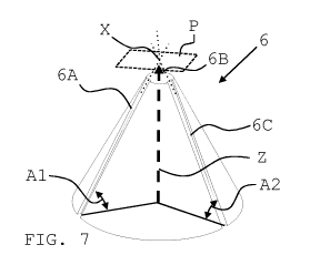
Figure 7 shows a nozzle according to a first embodiment.
Figure 8 shows a detail thereof.
Figure 9 shows a nozzle according to a second embodiment.
Figure 10 shows a nozzle according to a third embodiment.
Figure 11 shows a detail thereof.
Figure 12 shows a nozzle according to a fourth embodiment.
Figure 13 shows a nozzle according to a fifth embodiment.
Figures 14 - 16 shows cross sections of a nozzle according to the fifth
embodiment.
Figure 17 shows a three-dimensional view of this embodiment.
In Figure 1, the main components of an inhalation device according to the
invention are de-
picted schematically and not-to-scale, at the situation prior to first use.
The inhalation device comprises a housing 1, which is preferably shaped and
dimensioned
such that it can be held with one hand and can be operated by one finger, e.g.
the thumb (not
shown). Two reservoirs 2A, 2B for the respective storage of a medically active
liquid F1, F2
are located inside the housing 1. The depicted reservoirs 2A, 2B are designed
to be collapsi-
ble; that means that during proceeding emptying, the elastic or at least limp
walls buckle, so
that the negative pressure which is necessary for extraction of a certain
amount of liquid F1,
F2 is not, or almost not, increased. A similar effect can be achieved when a
rigid container has
a moveable bottom by means of which the interior volume of the respective
reservoir can
also be successively be reduced (not shown).
Further, the inhalation device comprises a pumping unit with two pumping
chambers 3A, 3B
within the housing 1 for generation of the desired pressures which are
necessary for emitting
liquid F1, F2 and nebulizing the same. The pumping unit can also comprise
additional, not
depicted components (push button, locking device, etc.).
CA 03067134 2019-12-12
WO 2018/234525
PCT/EP2018/066716
- 18 -
The pumping chambers 3A, 3B can be present within separate pumping units, as
shown in
the present example, or they can be present as integrated into one single
pumping unit (not
shown).
Pumping chambers 3A, 3B are fluidically connected with reservoirs 2A, 2B by
means of a re-
spective inlet check valve 4A, 4B. Check valves 4A, 4B serve for allowing
inflow of liquid F1,
F2 into the respective pumping chamber 3A, 3B, and block a back flow of liquid
F1, F2 into
reservoir 2A, 2B upon release of the not-depicted locking mechanism.
As a means for the storage of potential energy 7, a spring is provided which
is coupled with
one (upwards directed) end to the pumping chambers 3A, 3B and which is
supported at hous-
ing 1 (lower part of the figure).
The inhalation device further comprises two riser pipes 5A, 5B with at least
one respective
reservoir-facing, interior end 5A', 5B' which can be received in said pumping
chambers 3A,
3B. In other words, riser pipes 5A, 5B can at least partially be pushed into
pumping chambers
3A, 3B, resulting in a decrease of the interior volumes of pumping chambers
3A, 3B. The term
"interior volume" describes that volume which extends from the reservoir-
facing inlet of the
pumping chamber 3A, 3B to the place where the interior end 5A', 5B' of the
riser pipe 5A, 5B
is located. In the depicted situation, riser pipe 5A, 5B is almost entirely
contained in the re-
spective pumping chamber 3A, 3B. As a result, the respective interior volume,
situated be-
tween check valves 4A, 4B and the interior end 5A', 5B' of riser pipes 5A, 5B,
is at a minimum.
Preferably, in the section which serves for the reception of the riser pipes,
pumping chamber
3A, 3B has section with an circular inner cross section that corresponds to
the (then also)
circular outside cross section of the according riser pipe section. Of course,
other cross sec-
tion shapes are possible as well.
According to the depicted embodiment, check valve 4A, 4B is arranged between
reservoir 2A,
2B and inlet of pumping chamber 3A, 3B.
Further, the inhalation device comprises a nozzle 6 which is connected liquid-
tight to the re-
spective exterior ends 5A", 5B" of riser pipes 5A, 5B. Nozzle 6 is suitable
for nebulizing /
atomizing liquid by using the principle of two colliding liquid jets. The
nozzle 6 which is de-
picted as an example comprises two ejection channels 6A, 6B. At a time, each
of the two noz-
zle's ejection channels 6A, 6B are connected to an individual pumping chamber
3A, 3B and
CA 03067134 2019-12-12
WO 2018/234525
PCT/EP2018/066716
- 19 -
thus, liquid reservoir 2A, 2B, such that a collision point which can be fed
with a different liq-
uids is provided. Each liquid F1, F2 has its own pumping chamber 3A, 3B in
order to avoid
undesired mixing.
Preferably, the cross sections of the liquid-containing channels are
relatively small, and typ-
ically, in the region of microns. In the example, the angles of the ejection
channels 6A, 6B with
respect to the main axis Z (dashed line) are such that their ejection
trajectories (dotted lines)
intersect in one common collision point X.
Also depicted is an optional outlet valve 8A, 8B inside riser pipe 5A, 5B for
avoiding back flow
of liquid or air into the exterior end 5A", 5B" of the same from the outside.
Outlet valve 8A,
8B is arranged in the interior end 5A', 5B' of riser pipe 5A, 5B. Liquid F1,
F2 can pass outlet
valve 8A, 8B in direction of nozzle 6, but outlet valve 8A, 8B blocks any
undesired back flow
in the opposite direction.
As can be seen in Fig. 1, riser pipe 5A, 5B is designed immobile and firmly
attached to housing
1, indicated by the connection in the region of exterior end 5A", 5B" with
housing 1. Riser
pipe 5A, 5B is also firmly attached to nozzle 6, which in turn is attached to
housing 1 as well.
On contrary, pumping chamber 3A, 3B is designed to be moveable with respect to
housing 1
and nozzle 6. The benefits of this design have already been explained;
reference is made to
the respective sections above.
Referring to Figure 2, a device similar to the one of Fig. 1 is depicted.
However, the embodi-
ment shown in Fig. 2 lacks the (optional) outlet valves 8A, 8B. All other
substantial compo-
nents are present, and also the function is comparable.
Figure 3, wherein some of the previously introduced reference numbers have
been omitted
for the sake of clarity, shows the embodiment of Fig. 1 just before initially
filling the pumping
chambers 3A, 3B. Pumping chamber 3A, 3B is pulled down, loading the means for
the storage
of potential energy 7. Outlet valve 8A, 8B is closed due to underpressure
inside pumping
chamber 3A, 3B, and check valve 4A, 4B is open to reservoir 2A, 2B.
Increasingly collapsing
walls of reservoir 2A, 2B allow its inside pressure remain nearly constant,
while pressure
inside pumping chamber 3A, 3B drops because of the upwards motion pulling
pumping
chamber 3A, 3B off riser pipe 5A, 5B, increasing the respective interior
volume of pumping
CA 03067134 2019-12-12
WO 2018/234525
PCT/EP2018/066716
- 20 -
chamber 3A, 3B.::stplAs a result, respective interior volume of pumping
chamber 3A, 3B fills
with liquid F1, F2 from reservoir 2A, 2B.
In Figure 4, the situation during the first activation of the inhalation
device is shown. Means
for the storage of potential energy 7 has been released from the loaded
position as shown in
Fig. 3. It pushes the pumping unit comprising pumping chamber 3A, 3B onto
riser pipe 5A,
5B, the interior end 5A', 5B' of which coming closer to check valve 4A, 4B now
being closed.
As a result, the pressure inside pumping chamber 3A, 3B rises and keeps valve
4A, 4B being
closed, but opens outlet valve 8A, 8B. Liquid F1, F2 rises inside riser pipe
5A, 5B towards its
exterior end 5A", 5B" and nozzle 6.
Figure 5 shows the situation at the end of the first activation. Means for the
storage of poten-
tial energy 7 is in its most relaxed end position (spring fully extended).
Also, pumping cham-
ber 3A, 3B has been pushed almost entirely onto according riser pipe 5A, 5B
such that the
respective interior volume of pumping chamber 3A, 3B reaches its minimum. Most
of liquid
F1, F2 previously contained inside pumping chamber 3A, 3B has passed outlet
valve 8A, 8B
into riser pipe 5A, 5B. Liquid F1, F2 already contained within riser pipe 5A,
5B has been
pushed towards, and though, through ejection channels 6A and 6B of nozzle 6,
where the
desired nebulization takes place, producing a spray at common collision point
X.
In Figure 6, the situation after re-filling the pumping chamber 3A, 3B is
depicted. Pumping
chamber 3A, 3B has again been pulled off interior end 5A', 5B' of riser pipe
5A, 5B, increasing
the respective interior volume of pumping chamber 3A, 3B. Means for the
storage of potential
energy 7 has been loaded (spring compressed). During movement of pumping
chamber 3A,
3B away from riser pipe 5A, 5B, a negative pressure develops in the interior
volume, closing
outlet valve 8A, 8B and opening check valve 4A, 4B. As a result, new liquid
F1, F2 is drawn
from reservoir 2A, 2B into pumping chamber 3A, 3B. The inhalation device's
pumping cham-
ber 3A, 3B is filled again and ready for the next ejection of liquid F1, F2 by
releasing the spring.
In Figure 7, a nozzle 6 comprising three ejection channels 6A, 6B, 6C is
depicted. The ejection
trajectories (dotted lines) intersect in one common collision point X. This
collision point is
located in plane P having a perpendicular orientation with respect to the main
axis Z (this is
the common orientation of the plane in which the collision point lies
throughout this docu-
ment, if not stated otherwise). All channels 6A, 6B, 6C are arranged
symmetrically and three-
dimensionally around main axis Z. The ejection angles (also plotted in Figure
8 which is a
CA 03067134 2019-12-12
WO 2018/234525
PCT/EP2018/066716
- 21 -
detailed view of the nozzle tip; only angles Al, A2 are shown) as defined
herein are identical.
The line from which the intemediate angle I is measured is the main axis;
thus, the interme-
diate angle is the collision angle. In this example, all individual
trajectories are positioned on
the surface of a truncated cone. Since the surface 6' of the truncated cone is
parallel to the
base circle (no reference numeral), in this example, the angles Al, A2
measured at both loca-
tions are identical. Preferably, the channels 6A, 6B, 6C are (laterally)
closed with a closure
such as a lid (not shown) or the like in a way that liquid (not shown) can
pass through the
channels, but cannot leave them in undesired (lateral) directions. This can
e.g. be achieved in
placing the truncated cone inside a cone shaped cap (not shown), the wall(s)
of which form (s)
a lid for the channels. The channels can be fabricated on the surface of the
truncated cone as
shown, but also as trenches in the surface of the cap.
Both types can be combined with each other, in that channels are provided
alternating in
cone and opening, or in that associated half-channels are provided in cone and
opening.
In Figure 9, a cross sectional view of a nozzle 6 is shown wherein, with
respect to the nozzle's
6 main axis Z, again, all ejection angles A are identical (only one reference
numeral A plotted);
thus, all intermediate angles are the same as well, and they are all measured
against the main
axis Z. However, the ejection channels 6A - 6D lie in a common cross sectional
plane (hatching
omitted), such that different collision points Xl, X2 are provided. These are
located in differ-
ent planes P1, P2 perpendicular to the main axis Z, i.e. collision point X1
and X2 have different
distances to the front surface 6' of nozzle 6. At the same time, all collision
points Xl, X2 are
located on main axis Z. Ejection channels 6A and 6B form a first pair, and
ejection channels
6C and 6D form a second pair. In this example, nozzle 6 is constructed as a
"two-dimensional"
block.
The present example can be used to produce a central stream (not shown) of an
aerosol of a
first liquid, and a surrounding sheath stream of an aerosol of a second
liquid.
In Figure 10, an embodiment is shown wherein the ejection channels 6A - 6D are
once again
located on the surface of a truncated cone. In this setup, the ejection angles
Al, Al' of a first
pair of ejection channels 6A, 6B correspond to the ejection angles A2, A2' of
a second pair of
ejection channels 6C, 6D. However, due to ejection offsets the setup results
in two different
collision points X1 and X2. Figure 11 is a detail of the tip of the nozzle.
Note that angles Al,
CA 03067134 2019-12-12
WO 2018/234525
PCT/EP2018/066716
- 22 -
A2 in Fig. 10 are the same as in Fig. 11 since the base circle of the cone is
parallel to the surface
6' of the truncated cone.
As can be seen in Fig. 10, for example, trajectory of channel 6B is slightly
tilted away from the
main axis Z in one direction, namely in direction of angle Al", whereas
trajectory of channel
6D is tilted in the opposite direction, namely in direction of angle A2".
Also, (pesently similar)
angles Al and A2 are slightly smaller than angles Al* and A2* which start at
the thin dashed
lines. These represent lines that start at the base circle of the cone and end
at its imaginay
tip; channels along the thin dashed lines would have identical angles Al, A2
(and Al', A2', as
well as Al", A2") as well, but also result in one common collision point.
Therefore, in this
example, two pairs of ejection channels 6A, 6B and 6C, 6D are provided, all
having identical
ejection angles Al, A2, Al' A2' (see Fig.11), and thus, two collision points
Xl, X2 are provided,
as in the previous example. A lateral ejection offset D exists which is the
result of the aforesaid
placement of angles. In this embodiment, along the nozzle's main axis Z, all
collision points
Xl, X2 are located within the same plane (not shown) with respect to the
nozzle's 6 front
surface 6'. At the same time, all collision points Xl, X2 a located laterally
offset from main axis
Z (lateral ejection offset D).
Figure 12 depicts a nozzle 6 with four ejection channels 6A - 6D whose
ejection trajectories
have pairwise different ejection angles (Al and Al' are similar, as well as A2
and A2'),
wherein the ejection channels (and the trajectories) lie in a common plane
(hatched cross
sectional plane). Nozzle 6 is again of the "two-dimensional" block-type. The
angles Al, Al',
A2, A2' are arranged in such a way that all ejection trajectories (dotted
lines) intersect in one
common collision point X.
In Figure 13, a transparent top view on another embodiment of a nozzle is
shown. For fur-
ther details, reference is made to the description of Figures 12 - 15 below
which relate to the
same embodiment.
In Figures 14 and 15, two cross sections A-A and B-B of nozzle 6 from Fig. 11
are shown
(hatching omitted) wherein the ejection channels 6A, 6B and 6C, 6D are
connected to an up-
stream arranged common splitting chamber 9A, 9B. Thus, a separate chamber, or
volume, is
provided that is arranged between pumping chamber (not shown) and ejection
channels 6A,
6B / 6C, 6D, which has the purpose of splitting the liquid fed to the nozzle
(optionally from
several sources) before feeding it to the ejection channels 6A, 6B / 6C, 6D.
CA 03067134 2019-12-12
WO 2018/234525
PCT/EP2018/066716
- 23 -
In the depicted embodiment, two of the nozzle's 6 ejection channels 6A and 6B
as well as 6C
and 6D form a respective pair, and one main feed channel 10A, 10B is arranged
to connect
with the beginning of the first ejection channel 6A, 6C and a cross channel
11A, 11B exists
that connects said main feed channel 10A, 10B with the end of the respective
second ejection
channel 6A, 6C. The cross channel 11A, 11B which serves as splitting chamber
9A, 9B runs
perpendicular to main feed channel 10A, 10B. Only one respective inlet opening
12A, 12B
exists which must be coupled to a pumping chamber or pumping unit (not shown).
In the depicted embodiment, the initially overlapping pairs of ejection
channels, with respect
to the main axis Z (not shown) which then also forms a symmetry axis, are in
rotated posi-
tions relative to one another, e.g. by 600 (or another integer factor of 360
), and the respective
cross channels 11A, 11B are, along said symmetry axis, spaced apart from one
another, in
order not to intersect with each other.
In Figure 16 which is a transparent side view, a cross section containing
hidden lines is de-
picted, such that all main axially spaced apart cross channels (third cross
channel with refer-
ence numeral omitted) are well visible. Only two pairs of ejection channels
can be seen be-
cause of the view direction.
The aforementioned design can also be seen in Figure 17 which is a three-
dimensional trans-
parent view of nozzle 6 containing the cross sections of Figs. 14 and 15. By
virtually rotating
the cross sections, a compact and simple nozzle is obtained whose inlet
openings (reference
numerals omitted) are located on a circular path (dash-dotted circle). Thus,
the respective
interface to the upstream arranged component (i.e. pumping chamber, valve
section, not de-
picted) can be designed to be relatively simple.
CA 03067134 2019-12-12
WO 2018/234525
PCT/EP2018/066716
- 24 -
List of references
1 housing
2,2A,2B reservoir
3,3A,3B pumping chamber
4,4A,4B check valve
5,5A,5B riser pipe
5A',5B' interior end
5A",5B" exterior end
6 nozzle
6' front surface
6A-6D ejection channels
7 means for the storage of potential energy
8,8A,8B outlet valve
9A,9B splitting chamber
10,10A,10B main feed channel
11,11A,11B cross channel
12,12A,12B inlet opening
F,F1,F2 liquid
X,X1,X2 collision point
A,A1,A2 ejection angle
A1*,A2*,A1',A2',A1",A2" angle
I intermediate angle
Z main axis
D ejection offset
P,P1,P2 plane