Note: Descriptions are shown in the official language in which they were submitted.
1
SYSTEM AND METHOD FOR PROFILING A USER
FIELD OF THE INVENTION
This invention relates to a method and system for determining a user's path.
Further, this
invention also relates to a method and system for determining the location of
a user. More
specifically, this invention relates to a method and system for tracking a
user within an indoor
or outdoor area, such as a hospital, a college campus, a sports arena or an
airport This
invention also relates to a method and system for determining a user's path
for operational
and planning purposes, and in particular to a method and system for
determining the
residence time of a user in a zone.
The invention also has application in providing real time information to
passengers, as well
as to the scheduling of services so that airport authorities can react to any
build up of
passengers in critical areas such as security screening, immigration checks,
baggage and
so on.
BACKGROUND OF THE INVENTION
In the past, airports have had difficulty getting historical and real-time
information regarding
the behaviour of passengers within and around an airport.
One solution to this problem is to use Bluetooth (Bluetooth is a registered
trade mark of
Bluetooth SIG, Inc, Washington, United States of America) or Radio Frequency
Identification
(RFID) tags. However these solutions have the following limitations:
RFID tags are not typically carried by passengers and therefore cannot be used
without specifically issuing them to passengers.
Bluetooth is a short range protocol limited to small areas of the airport.
- Bluetooth is not commonly active in passenger smart telephone devices,
thereby
limiting the accuracy of any measurements.
Bluetooth relies on Bluetooth Access Points in fixed locations. It is
relatively complex
and time consuming to relocate them if necessary.
Another solution is to use a WiFi triangulation method to track passenger
smart telephones.
WiFi uses a wireless connection between a user device and an access point to
transfer
data between the user device and access point. WiFi is a registered trade mark
of Wi-Fi
CA 3067170 2020-01-08
=
2
Alliance, San Jose, United States of America. Usually, the access point has a
wired
connection to a local area network (LAN). However, a problem with this
approach is that
WiFi devices do not emit a continuous stream of data. This is because a device
will only be
detected when a user is actually using the airport WiFi infrastructure.
This means that for any given device, it may be detected only sporadically
throughout the
airport. For example, a device may be detected while a passenger is using
their telephone
in a café, or at a gate area, but not while walking from check in to security
zones. This is of
course problematic for live dwell time measurements because this sporadic data
is not
representative of what is actually happening in the airport.
Embodiments of the invention seek to address the above problems by using WiFi
signals
emitted through passenger smart telephones, and other devices, to provide
location data
which can be used to locate, track. and measure the activities of passengers
throughout the
airport campus. The location data is processed to remove poor quality data and
the
remaining data is used to determine a passenger's path and associated dwell
time
information. This data can then be used to provide real time measurements for
any section
of the airport.
Embodiments of the invention, which may be referred to as and Indoor Anonymous
Dwell
Time Tracking system, are a multi component service that:
1. Allows airport staff to define arbitrary zones in the airport.
2. Locates devices using triangulation of WiFi signal strength
3. Associates these devices to a zone in an airport
4. Charts the path of devices in these spaces.
5. Maintains a live set of continuous device detections for devices
detected in the
airport
6. Uses this zone and device path data to determine the dwell time in any
zones
across the airport.
Embodiments of the invention. improve on existing RFID systems because the
passengers/consumers being tracked do not need to be given a RFID token to
carry, and
do not necessarily need to be informed that their movements are being tracked,
which can
subconsciously change behaviour.
CA 3067170 2020-01-08
=
3
Embodiments of the invention improve on Bluetooth systems because WiFi covers
the
entire airport campus, not just small specific areas. Therefore it is possible
to provide
sophisticated measurements such as "show current wait time for passengers in
immigration
who started in international arrivals". It also improves on Bluetooth systems
because the
zones being measured are arbitrary and are not tied directly to the location
of access
points. In this regard, in a Bluetooth system, if an airport wants to modify
the zone being
measured, it is necessary to physically move the Bluetooth sensors. In the
present
invention, the airport staff just need to configure the new zone using a
Google Map
application.
Embodiments of the invention improve on basic WiFi triangulation because it
can maintain
a live device path, storing all the previous zones a device passed through,
and use this
data to determine if the data is suitable or not for live dwell time
measurements.
SUMMARY OF THE INVENTION
According to a first aspect of the present invention, there is provided a
system for
determining the path taken by a user through one or more zones. The system may
comprise: a location server arranged to receive location data indicative of
the location of a
communication device associated with the user, the location data defining the
position of
the communication device at a plurality of different points in time, the
location server further
arranged to receive sequence data associated with the location data indicative
of the order
in which the location data was determined; and a path determining means for
determining
the path of the user through the zone, the user's path being defined by at
least a portion of
the received location data; and a comparator for comparing the determined path
of the user
with on or more predetermined user paths. The location server processes the
received
location data depending upon the result of the comparison. Preferably, the
location server
corrects the determined user path with the process location data.
According to another aspect of the present invention, there is provided a
system for
processing user location data comprising: a location server arranged to
receive location
data of a communication device associated with the user, the location data
defining the
position of the communication device at a plurality of different points in
time, the location
server further arranged to receive sequence data associated with the location
data
indicative of the order in which the location data was determined; path
determining means
for determining the user's path defined by the received location data and the
associated
sequence data; and a comparator for comparing the determined path of the user
with one
CA 3067170 2020-01-08
4
=
or more predetermined user paths. Each predetermined path is preferably
defined by further
location data and associated sequence data indicative of the order of the
further location data.
The location server is configured to process the received location data
depending upon the
result of the comparison. Usually, the location data is determined based on
signal strength
data which is usually received by-an access point from a mobile device.
In yet a further aspect of the present invention, a method for processing user
location data is
provided. The method comprises receiving, with a receiver, location data of a
communication
device associated with the user, the location data defining the detected
position of the
communication device at a number of different points in time, and receiving,
with the receiver,
sequence data associated with the location data indicative of the order in
which the location
data was determined; determining, using a processor, the user's path passing
through points
defined by the received location data and the associated sequence data; and
Comparing, using
the processor, the determined path of the user with one or more predetermined
user paths; and
processing, using the processor, the received location data depending upon the
result of the
comparison. Preferably, the determined user path is corrected or updated with
the processed
location data.
In yet a further aspect of the present invention, there is provided a system
for profiling a user
comprising: a server arranged to receive location data of a communication
device associated
with the user, the location data defining the detected position of the
communication device at a
number of different points in time, the server further arranged to receive
sequence data
associated with the location data indicative of an order in which the location
data was
determined, the server further arranged to compare the received location data
with zone data
defining a plurality of zones and to associate the received location data with
one of the plurality
of zones; and path determining means for determining a user's path through
a'first sequence of
zones, wherein the server is further arranged to associate the user with one
or more
predetermined user types based on the determined path.
CA 3067170 2020-01-08
4a
In yet a further aspect of the present invention, there is provided a method
for profiling a user
comprising: receiving location data of a communication device associated with
the user, the
location data defining the detected position of the communication device at a
number of
different points in time; receiving sequence data associated with the location
data indicative of
the order in which the location data was determined; comparing the received
location data with
zone data defining a plurality of zones; associating the received location
data with one of the
plurality of zones; determining the user's path through a first sequence of
zones; and
associating the user with one or more predetermined user types based on the
determined path.
BRIEF DESCRIPTION OF THE DRAWINGS
Embodiments of the invention will now be described, by way of example only,
and with
reference to the accompanying drawings, in which:
Figure 1 is a schematic representation of the main functional components
embodying
the invention;
Figure 2 is a screen shot of a zone editor embodying the invention which may
be used
to select, create, edit or delete different zones in the airport to track a
user's device;
Figure 3 is a screen shot.of an editor embodying the invention in which a high
quality
device path in the airport is visualised in a particular zone;
Figure 4 is a screen shot of an editor embodying the invention in which a
lower quality
device path in the airport is visualised in a particular zone;
Figure 5 is a histogram showing live dwell time data obtained by embodiments
of the
invention; and
Figure 6 is a flow diagram showing the main steps performed by an embodiment
of the
invention.
CA 3067170 2020-01-08
5
The following description is of a system for use in the aviation industry, but
this is
exemplary and other applications of the invention will also be discussed. For
example, the
system may be used in any indoor or outdoor area where a user carries a WiFi
enabled
device, such as a hospital, a college campus, a sports arena and so on.
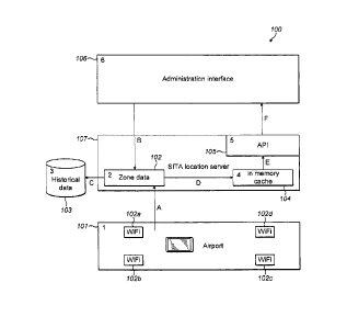
Referring now to figure 1, this shows a schematic representation of a system
100 according
to an embodiment of the invention. Operation of the various components will be
explained
in further detail below.
The system 100 may be directed towards the tracking of users in an airport 101
having a
plurality of WiFi access points 101a ¨ 101d providing at least part of a WiFi
infrastructure in
the airport 101. Each access point 101a - 101d may be positioned at a
different location in
the airport 101.
The WiFi infrastructure may use Real-time Locating System (RTLS) triangulation
to locate
a passenger's smart telephone or other mobile communication device as will be
known to
the skilled person.
In the embodiment shown in figure1, a location server 107 is communicatively
coupled to
the airport WiFi infrastructure 101a ¨ 101d. The location server 107 may, be
coupled to the
airport infrastructure via a wireless link or a wired link. The sever 107 may
run in an airport
data centre or as a cloud service over a number of servers, which are usually
positioned in
different locations.
The server 107 may communicate with the airport network by means of an
Application
Programming Interface, API, that is provided by a WiFi vendor or provider. The
server 107
may use a particular provider's API to obtain the raw location data from the
airport.
The location server 107 may comprise a historical data store 103 for storing
the determined
movement of devices in the airport. The historical data store may be provided
as part of the
location server as a hard disk or solid state memory or other local storage
means.
Alternatively the historical data store 103 may be a separate store located in
a different
position to the location server 107, such as a hard disk or solid state memory
or other
remote storage means. The historical data store may store both historical
reference data
and also data identifying devices belonging to airport staff or
infrastructure. In either case,
the historical data store 103 is communicatively coupled a zone data component
102 which
may be part of the location server 107. This may be using a wired or wireless
connection. A
CA 3067170 2020-01-08
6
zone refers to a spatial area in the airport in which dwell time measurements
are to be
made. Examples of zones are: Security, Baggage, Immigration, Retail, or Check
in.
The zone data component 102 may store a definition of the zones of interest in
the airport,
for example: airside, landside, security, baggage, retail and so on. The data
component
102 may store the zone definitions on a hard disk or solid state memory or in
other storage
means. The airside part of the airport is usually the part of the airport that
is accessible only
after a passenger has gone through boarding card and x-ray security checks.
The landside
part of the airport is usually the part before a passenger has gone through
boarding card
and x-ray security checks. It is also useful to note that arriving passengers
emerges from
the baggage hall into the Landside area.
In the example shown in figure 2, and described in further detail below, there
are three
terminals, Ti, T2, and T3. Each terminal comprises a plurality of zones. For
example,
terminal Ti may comprise the following zones: Airside ¨ First Floor, Airside -
Ground Floor,
and Landside zones. Terminal T2 may comprise Duty Free, Food, Retail, Airside,
Check in,
Landside-First Floor, and Landside ¨ Ground Floor zones. Further, Terminal T3
may
comprise Baggage and Check in zones, although the above definitions of which
zones are
associated with which terminal are exemplary only.
The zones are defined as are virtual spaces. A user may define each zone by
dragging a
polygon out on a map application, such as an internet browser map application
running on
an administration interface 106. One example of a suitable internet browser
map
application is a Google maps application. Defining a zone is similar to
creating a polygon
.. shape in Microsoft Powerpoint. Google is a registered trade mark of Google
Inc., USA, and
Microsoft and PowerPoint are registered trade mark of Microsoft Corporation,
USA.
It is only necessary to define zones in a region of the airport where access
points exist.
However, one or more physical access points may be added to or removed from a
particular zone without modifying the virtual zones. Furthermore, virtual
zones may be
redefined without having to modify any airport infrastructure. This addresses
one of the
problems with Bluetooth identified above in that embodiments of the invention
may allow a
change in the area being measured or monitored without physically moving
access points.
In figure 1, the arrow labelled B pointing from the administration interface
towards the zone
data component schematically shows how the administration interface sends data
defining
a particular zone to the zone data component. The data defining each zone may
be data
=
CA 3067170 2020-01-08
7
defining a polygon and preferably associated data defining the position of
each access
point in the polygon.
The server may also comprise an in-memory cache 104. The cache 104 stores data
indicative of the current active devices that are being tracked in the
airport, including their
current position and zone. The cache may also store an in-memory
representation of a
path a device has taken as it moves thorough the airport. A path may be
defined by the
curve line or shape which links or joins a sequence of data points indicative
of the position
of the device. The sequence of the positional data is usually ordered in a
chronological
order.
An example of this representation is shown in figures 3 and 4 of the drawings,
described in
further detail below. Figure 3 is an example of a device path that is
considered a high
quality device path. There are plenty of device detections with good accuracy
in the desired
measurement zone. Figure 4 is an example of a device path that is considered
low quality
compared to the device path shown in figure 3. There are more infrequent
detections than
the higher quality device path shown in figure 4. The path shown in figure 4
is an example
of the type of problematic data quality that the invention seeks to adderss.
The server 107 may also comprise an Application Programming Interface (API)
105. The
API provides a way to access the data stored in the in-memory cache 104.
In the embodiment shown in figure 1, the API 105 is communicatively coupled to
an
administration interface 106 and the in-memory cache 104. The administration
interface is
described in further detail below. Further, the in-memory cache 104 is
communicatively
coupled to the zone data component 102 and to the API 105. Further, in the
embodiment
shown in figure 1, the zone data component 102 is communicatively coupled to
both the
historical data store 103 and the airport WiFi infrastructure 101.
The administration interface 106 uses the API 105 to access the memory cache
data 104.
The administration interface sends a request via the API 105 to access the
memory cache
data 104. The arrows E and F shown in figure 1 represent the memory cache data
104
being sent to the administration interface 106 in response to that request.
As previously described, the system 100 may comprise an administration
interface 106
tool. This tool may be used to define the zones and to display the data
returned from the
API. The administration interface tool 106 is usually provided on a separate
or different
=
CA 3067170 2020-01-08
8
server to the location server 107 however, they can in principle be provided
on a single
server. In either case, the administration interface 106 is communicatively
coupled to the
zone data component 102 and the'API 105 within the location server 107.
The various steps performed by an embodiment of the invention will now be
described in
further detail below, referring to the flow diagram shown in figure 6. In some
embodiments,
not all of the steps shown in figure 6 will be performed, and the steps do not
necessarily
have to be performed in the order shown in figure 6.
At step 201, an airport operator uses the Administration Interface 106 to
define the zones in
the airport. A zone may be defined as a polygon having a plurality of lines
joined by a
number of vertices. Usually, the polygon is a closed shape so that a user has
to cross one
of the lines or zone boundary when leaving a zone.
The zone data may be stored in the Zone Data component 102. In addition, the
zone data
may also be stored offline in the Historical Data Store 103, but it is
sufficient for the zone to
be stored in a single storage means. An example of a baggage zone is shown in
figure 2 as
a filled black polygon area.
At step 203, the Location Server 107 polls the Airport WiFi infrastructure via
a third party
server. Usually, the airport WiFi infrastructure is provided by a third party,
and therefore the
location server 107 polls a third party server which in turn requests data,
such as location
data associated with all devices which may have moved since the last poll
request. Usually,
the third party server polls the Airport WiFi infrastructure in a periodic or
regular manner.
.. The server may poll the WiFi infrastructure approximately every 15 seconds.
However,
although the polling may be periodic, the received location data of each
device is usually
irregular in nature. This is because the airport WiFi infrastructure does not
have control as
to whether it receives a signal from a device. For example, if a device is
temporarily
switched off, then no location data of that device will be received by the
location server
when the device is switched off.
The third party server performs triangulation of the devices as the devices
use the WiFi
network. The third party server does this by well known triangulation methods
familiar to
the skilled person. The third party server sends to the location server
location data of each
mobile device which has been detected by the third party server. This allows
the location
server 107 to receive data associated with all devices that have moved since
the last poll
CA 3067170 2020-01-08
9
request. The arrow labelled A, shown in figure 1 represents this data being
sent from the
third party location server to the location server 105.
The quality of the data received from the third party server may be determined
based on an
accuracy value provided by the third party provider. Data quality may be
determined based
on the signal strength or, the number of access points which can see each
device, or both.
In addition, the location data may be time-stamped. This provides additional
data indicative
of when the location data of a particular device was determined. The system
may
determine the frequency of detections by comparing the time stamp of
sequential location
data messages received by the location sever 107.
The third party server then sends raw, or in other words, unprocessed location
data to the
location server 107. The unprocessed location data may include absolute
positional data of
each device i.e. longitude and latitude of each device in an airport or in
other words, the x
and y coordinates of the devices. Usually, the received location data of each
device does
not depend upon the location of the access point which each device is
communicating with.
Accordingly, the received location data of each device may be independent of
the position
of each access point.
At step 205, the location server 105 receives from the third party
triangulation server data
determining the location of all mobile devices which are active within the
airport. This may
be performed every 15 seconds, but can be performed more frequently or less
frequently
than this. After the server has received the location data at step 205, the
location server
may determine the user's path defined by the received location data and the
associated
sequence data defining a plurality of points on the path, at step 207. At step
209, the
location server compares the determined path of the user with one or more
predetermined
user paths. At step 211, the location server processes the received location
data
depending upon the result of the comparison. At step 213, the location server
corrects or
updates the determined user path based on the comparison.
In some embodiments, the raw data received by the location server 107 may be
combined
or associated with the Zone Data to give it context. This is done by
determining whether or
not each device is within the boundary defining a particular zone. If it is
determined that a
particular device is located in a particular zone, then the location data
associated with that
device is also associated with the zone in which the device is located.
=
CA 3067170 2020-01-08
10
For example, the location server 107 may compare the location data i.e. the
coordinates of
a device with the coordinates defining a zone. If a device is determined to be
inside the
boundary of a polygon defining the zone under consideration, then the location
server 107
associates that zone with the data structure for each device.
The combined or associated data may be referred to as contextual data. The
data is
combined by the server 107 and then stored in an in-memory (and preferably
database)
data structure. There is a data structure for each device detected. This data
structure
contains the coordinates, for example the abscissa (e.g. x coordinate) arid
ordinate (e.g. y
coordinate) of the device.
In other words, each device is associated with a zone at each detected
location. Usually, a
plurality of devices are associated with each zone. In the example shown in
figure 3, there
are 5522 device paths are found, ready for an operator to review.
For example, there may be many people waiting in security or baggage zones at
peak time.
If there are 100 people waiting, and the server receives data detecting around
10% of
them, then there would be 10 devices active in security or baggage.
Although not essential to all embodiments, the contextual location data may be
stored in
the Historical Data Store 103. ,
The contextual location data may also be updated in the In Memory Cache 104,
storing a
real time representation of the movements of all devices in the airport, as
shown in figure 3.
The contextual data may be Stored in both store 103 and memory cache 104 so
that a)
any airport staff may be automatically identified during nightly processing
because they are
in the airport longer than is typical for passengers, and b) so that the
airport can use the
data for historical comparison..
Each time the data is polled, the live dwell time may be determined for each
device within
each zones. This is described in further detail with reference to a particular
Live Dwell Time
Algorithm below.
For each communication device, the dwell time may be determined by determining
the time
when a user was first detected within a zone, and the time when the user was
last detected
within a zone (before the user moved do a different zone). The dwell time may
be
CA 3067170 2020-01-08
11
computed as the difference in time between the last detection time within a
zone and the
first detection time within a zone. In the histogram shown in figure 5, the
number of devices
within security is determined as function of wait or dwell time: 5 devices
have a dwell time
of less than one minute; 6 devices have a dwell time of 1 minute; a further 6
devices have a
dwell time of 2 minutes; a further 6 devices have a dwell time of 3 minutes; 2
devices have
a dwell time of 4 minutes; 2 further devices have a dwell time of 5 minutes;
while finally, 2
devices have been determined to have a dwell time of 6 minutes in security.
Steps 203,
205, 207, 209, 211, and 213 may be repeated as updated location data is
received by the
location server 107.
The dwell time is the amount of time that passengers spend in a particular
area (i.e. a
Zone) of the airport. This term is interchangeable with Wait Time. Dwell Time
is used in
areas of an airport that a passenger wants to be in for example retail, food
hall. Wait Time
is used in areas of an airport that a passenger doesn't want to be in, for
example check in,
security, baggage collection.
The data may be made accessible to 3rd parties via the API. In other words,
3rd parties
may access the data stored in the historical data store 103 (and the in memory
cache 104).
This live data is in stored in memory 104, while the historic data is stored
in historical data
store 103. The data (both real time or historical or both) may be viewed using
the
Administration Interface 106, as shown in figure 4, although this step is in
fact optional.
The processing, using an algorithm, of the raw WiFi positional data of each
mobile device
within the airport will now be described in further detail. The algorithm uses
the received
positional data to determine live dwell time of each mobile device within the
airport. This
algorithm may be performed every time the location server 107 refreshes the
location of
devices in the Airport.
When measuring the live dwell time for a given zone such as security, it is
necessary to
factor in the following data quality problems:
1. Staff and static WiFi devices (e.g. staff personal computers (PCs)) in
the security
should be filtered out.
2. The sporadic and periodically inaccurate nature of WiFi data means that
devices
that are passing near to, but not through, the Security zone may be
incorrectly reported as
being in Security.
3. The number, accuracy and frequency of detections will vary for devices.
CA 3067170 2020-01-08
12
Embodiments of the invention address these data quality problems in a number
of different
ways.
Handling staff devices
The Location Server 107 maintains a dynamic list of staff and infrastructure
at the airport
(Historic Data 103 above). This list is automatically generated by monitoring
for devices
that are in the airport for a long time which may be typical of a staff member
working there,
or are frequently in the airport which may be typical of airport staff working
5 days a week.
Devices in the Security zone are then compared with this list and filtered out
from the
results.
=
Handling inaccurate or partial paths
Inaccurate WiFi data can be smoothed out or eliminated by using the typical
path of a
departing passenger through the airport. The following example refers to a
departing
passenger because it is described in conjunction with a security area, and
only departing
passengers pass through security. Nevertheless, the processing steps equally
apply to
other passenger types such as arriving passengers.
The device path can be used to profile the passenger as a Departing, Arriving
or Transfer
passenger. In addition the device path can be profiled as Airport Staff, or a
welcoming
agent also known as a Meeter/Greeter.
The typical path of a departing passenger is given by the following sequence
of zones:
LANDSIDE CHECK IN SECURITY AIRSIDE RETAIL GATE AREA
That is, a passenger arrives at the airport in the LANDSIDE zone, then CHECKS
IN, then
passes through SECURITY to the AIRS1DE zone. The passenger will typically
dwell in the
RETAIL area until ready for boarding and then go to the GATE AREA.
For the purposes of measuring dwell time in security, any paths that contain
LANDSIDE or
CHECKIN in the past, and do not contain AIRSIDE/RETAIL/GATEAREA can be
considered
good representative paths.
CA 3067170 2020-01-08
13
Examples of inaccurate paths caused by the sporadic nature of the WiFi data
are:
1. SECURITY [SLEEP] GATE AREA
This would be an example of a path where a device is first detected in the
SECURITY area,
then enters SLEEP mode where it is no longer detected by the WiFi
infrastructure, and
after a long period of time detected in GATEAREA. This is a bad path because
a) It is not
known how long the device was in SECURITY before it was first detected and b)
because it
entered a SLEEP mode and was undetected, it is not known how long it remained
there
before going AIRSIDE.
1. AIRSIDE GATE AREA BAGGAGE SECURITY LANDSIDE
This is an example of an arriving passenger who has arrived at AIRSIDE in the
GATEAREA, and walked to BAGGAGE to collect their bags. Before going LANDSIDE,
the
passenger is briefly (and incorrectly) detected in the SECURITY zone because
of poor WiFi
quality. This device path will therefore have to be eliminated from the dwell
time
measurements.
Because the full device path is maintained in memory, it is possible to filter
or remove these
bad quality paths by specifying filter criteria in the algorithm. The filter
criteria vary
according to the zone being measured, and therefore must be configurable for
the zone in
question. The following is an example of the filter criteria for two zones:
1. Security Zone
a. Device must be in Security Zone, or device must have just transitioned
out of
Security into AIRSIDE
b. Device must never have been AIRSIDE
c. Device must have previously been LANDSIDE
d. Device path must match profile for Departing Passenger
2. Baggage Zone
a. Device must be in Baggage Zone, or device must have just transitioned
out of
Baggage into LANDSIDE
b. Device must never have been LANDSIDE
c. Device must have previously been AIRSIDE
=
CA 3067170 2020-01-08
14
d. Device path must match profile for Arriving Passenger
Handling number, accuracy & frequency of detections
The live dwell time algorithm may factor in the number, accuracy & frequency
of detections
to determine the quality of any given device path for use. These three factors
are important
because:
1. In general, the more detections that of a particular device path, the
better quality of
that device path. Closely related to this is the accuracy and frequency of
these detections.
2. The accuracy can vary from detection to detection, caused by
environmental factors
at the airport. The higher the accuracy, the more reliable the data.
3. The frequency of detections varies along the device path (typically due
to whether
the passenger is using the device or not). Infrequent detections is a problem
because if a
device has not been detected for, say 2 minutes, it is not possible to tell if
the device is still
in Security or has moved out of Security. Figure 2 and 3 show examples of
device paths
with high and low frequency.
The algorithm factors in these three parameters when assigning a quality value
to the path.
Of particular importance are the frequency and accuracy of detections as the
device
transitions from CHECKIN to SECURITY and from SECURITY to AIRSIDE. If a
determination can be made with a'high degree of accuracy when a device moves
into/out
of SECURITY, then embodiments of the invention can determine with a high
degree of
accuracy how long the device spent in SECURITY.
The device path has to meet a quality threshold to be usable for zone dwell
time
measurement.
Accordingly, embodiments of the invention combine an arbitrary zone
definition, device
path profiling, device path filtering by history and device detection quality
profiling such that
that the variable and sporadic nature of WiFi signals can be processed. This
allows live (as
well as historic) dwell times of a user in any part of an airport to be
determined.
In some embodiments, a system for processing user location data is provided.
The system
comprisises
a. a location server arranged to receive location data of a
communication device associated with the user, the location data defining the
detected position of the communication device at a number of different points
in
=
CA 3067170 2020-01-08
15
time, the location server further arranged to receive sequence data associated
with
the location data indicative of the order in which the location data was
determined;
b. path determining means for determining the user's, path passing
through points defined by the received location data and the associated
sequence
data; and
c. a comparator for comparing the determined path of the user with one
or more predetermined user paths;
wherein the location server processes the received location data depending
upon the result of the comparison.
In some embodiments, a method fOr processing user location data is provided.
The method
comprises:
a. receiving, with a receiver, location data of a communication device
associated with
the user, the location data defining the detected position of the
communication device at a
number of different points in time, and receiving, with the receiver, sequence
data
associated with the location data indicative of the order in which the
location data was
determined;
b. determining, using a processor, the user's path passing through points
defined by
the received location data and the associated sequence data; and
c. comparing, using the processor, the determined path of the user with one
or more
predetermined user paths; and
processing, using the processor, the received location data depending upon the
result of
the comparison.
=
=
CA 3067170 2020-01-08