Note: Descriptions are shown in the official language in which they were submitted.
OPTICAL CLEANING CARTRIDGE
[0001] <Blank>
BACKGROUND
[0002] In various optically-based analysis units or instruments, such as
microscopic
imagers, DNA sequencers, and other laboratory equipment, samples may be
provided in, or
flowed through, removable cartridges that are positioned in the field of view
of an optical
sensor with various optical components, e.g., lenses, filters, etc. Such
removable cartridges
may be received and supported by a cartridge receiver, e.g., a mechanical
interface that
engages with the removable cartridge, secures the removable cartridge in
place, and
provides mechanical, electrical, and/or fluidic interfaces by which the
analysis unit can
interface with the removable cartridge.
SUMMARY
[0003] Details of one or more implementations of the subject matter
described in
this specification are set forth in the accompanying drawings and the
description below.
Other features, aspects, and advantages will become apparent from the
description, the
drawings, and the claims.
[0004] In some implementations, an apparatus may be provided for
cleaning an
optical component in an analysis unit that is configured to analyze, using the
optical
component, samples that are located in a removable cartridge during analysis.
The
apparatus in such implementations may include a cleaning cartridge frame that
is
configured to be receivable by and supported by a cartridge receiver of the
analysis unit that
is configured to receive and support the removable cartridge. The apparatus
may also
include one or more optical cleaning assemblies, each optical cleaning
assembly including an
1
Date Recue/Date Received 2021-06-09
CA 03067180 2019-12-11
WO 2019/199527
PCT/US2019/025397
absorbent cleaning pad and a compliant support structure that is proud of a
surface of the
cleaning cartridge frame and interposed between the cleaning cartridge frame
and at least a
portion of the cleaning pad.
[0005] In some implementations of the apparatus, the compliant support
structure
may include an elastomeric material and may have a first portion that is a
domed shape. In
some such implementations, the domed shape may have a radius that at least
substantially
matches a radius of curvature of a surface of the optical component that faces
towards the
cleaning cartridge frame when the apparatus is supported by the cartridge
receiver.
[0006] In some implementations of the apparatus, the absorbent
cleaning pad may
be a laminate including a microfiber layer and a foam layer interposed between
the
microfiber layer and the compliant support structure.
[0007] In some implementations of the apparatus, the cleaning
cartridge frame may
have a corresponding optical cleaning assembly well for each optical cleaning
assembly,
each corresponding optical cleaning assembly well may have one or more
sidewalls and a
floor, and each optical cleaning assembly may be located in the corresponding
optical
cleaning assembly well.
[0008] In some implementations of the apparatus, each optical cleaning
assembly
may further include a corresponding cover plate that is sized to at least
extend to the
sidewalls of the corresponding optical cleaning assembly well, each cover
plate may have an
aperture sized to allow the compliant support structure of the corresponding
optical
cleaning assembly to protrude through the cover plate, and at least a portion
of the
absorbent cleaning pad for each optical cleaning assembly may be sandwiched
between the
corresponding cover plate for the optical cleaning assembly and the cleaning
cartridge
frame.
[0009] In some implementations of the apparatus, the apparatus may further
include one or both of an alcohol detection sensor or a liquid detection
sensor. Such a
sensor may be positioned so as to detect, respectively, alcohol or liquid,
present in the
optical cleaning assembly well.
[0010] In some implementations of the apparatus, at least a portion of
the
absorbent cleaning pad may include an indicator that causes the portion of the
absorbent
cleaning pad to change color when exposed to a liquid. In some
implementations, the color
2
CA 03067180 2019-12-11
WO 2019/199527 PCT/US2019/025397
change may occur when the portion is exposed to isopropyl alcohol rather than
just a
generic liquid.
[0011] In some implementations of the apparatus, there may be one
optical cleaning
assembly, two optical cleaning assemblies, three optical cleaning assemblies,
four optical
cleaning assemblies, or more than four optical cleaning assemblies.
[0012] In some implementations of the apparatus, the apparatus may
include a re-
use prevention mechanism such as a radio-frequency identification tag, a bar
code, a quick
response (OR) code, a serial number, and/or a near field communication tag.
[0013] In some implementations, a kit may be provided that includes
one of the
apparatuses as well as a container of liquid cleaning agent, a syringe, and/or
a pipette.
[0014] In some implementations, a method may be provided that includes
a)
obtaining any of the apparatuses or the kit discussed above, b) applying a
liquid cleaning
agent to the absorbent cleaning pad of a first optical cleaning assembly of
the one of the
one or more optical cleaning assemblies, c) installing the apparatus into a
cartridge receiver
of an analysis unit, d) controlling the analysis unit to cause relative
vertical translation
between the cartridge receiver and an optical component of the analysis unit
such that the
optical component of the analysis unit and the absorbent cleaning pad of the
first optical
cleaning assembly come into contact with one another and such that the
absorbent cleaning
pad of the first optical cleaning assembly and the compliant support structure
of the first
optical cleaning assembly are compressed by a first amount, and e) controlling
the analysis
unit to cause relative horizontal translation between the cartridge receiver
and the optical
component so as to cause the absorbent cleaning pad of the first optical
cleaning assembly
to clean the optical component.
[0015] In some implementations of the method, (e) may include
controlling the
analysis unit to cause relative horizontal translation between the cartridge
receiver and the
optical component in a bowtie (N) pattern or a lemniscate (co) pattern for one
or more
times.
[0016] In some implementations of the method, the apparatus may be an
apparatus
having an absorbent cleaning pad that includes an indicator that causes the
portion of the
absorbent cleaning pad to change color when exposed to, in some
implementations, liquid
or, in other implementations, alcohol, and the method may further include
controlling the
analysis unit to cause the analysis unit to obtain imaging data of the
absorbent cleaning pad
3
of the first optical cleaning assembly prior to (d) or (e), and determining
that the liquid
cleaning agent has been applied to the absorbent cleaning pad of the first
optical cleaning
assembly based on a color detected in the imaging data.
[0017] In some implementations of the method, the method may further
include
controlling the analysis unit to cause the analysis unit to obtain imaging
data of the
absorbent cleaning pad of the first optical cleaning assembly prior to (d) or
(e), and
determining that the liquid cleaning agent has been applied to the absorbent
cleaning pad
of the first optical cleaning assembly based on reflectivity of the absorbent
cleaning pad
measured from the imaging data.
[0018] In some implementations of the method, the apparatus may have a
sensor as
discussed above, and the method may further include controlling the analysis
unit to obtain
a sensor reading from the at least one sensor prior to (d) or (e).
[0019] In some implementations, an analysis unit may be provided that
includes an
optical sensor head including an optical component, a cartridge receiver
configured to
receive and support a removable cartridge, and a controller including one or
more
processors and a memory. The one or more processors may be communicatively
connected
with the memory, and the memory may store instructions for controlling the one
or more
processors to: a) determine that an apparatus for cleaning an optical
component has been
installed in the cartridge receiver, b) cause relative vertical translation
between the
cartridge receiver and the optical component such that the optical component
and the
absorbent cleaning pad of a first optical cleaning assembly of the one or more
optical
cleaning assemblies of the apparatus come into contact with one another and
such that the
absorbent cleaning pad of the first optical cleaning assembly and the
compliant support
structure of the first optical cleaning assembly are compressed by a first
amount, and c)
cause relative horizontal translation between the cartridge receiver and the
optical
component so as to cause the absorbent cleaning pad of the first optical
cleaning assembly
to clean the optical component.
[0020] In some implementations of the analysis unit, the apparatus may
be an
apparatus with a re-use prevention mechanism, and the memory may further store
instructions for controlling the one or more processors to further cause the
analysis unit to:
obtain data from the re-use prevention mechanism, determine whether the
apparatus is
4
Date Recue/Date Received 2021-06-09
CA 03067180 2019-12-11
WO 2019/199527 PCT/US2019/025397
authorized to be used based on the data, and perform (b) and (c) only when the
apparatus is
determined to be authorized for use.
[0021] In some implementations of the analysis unit, the memory may
further store
instructions for controlling the one or more processors to further cause, as
part of (c),
relative horizontal translation between the cartridge receiver and the optical
component in
a bowtie (N) pattern or a lemniscate (00) pattern for one or more times.
[0022] In some implementations of the analysis unit, the apparatus may
include an
indicator that causes a portion of the absorbent cleaning pad to change color
when exposed
to liquid or, in some implementations, to alcohol. In such implementations,
the memory
may further store instructions for controlling the one or more processors to
further cause
the analysis unit to obtain imaging data of the absorbent cleaning pad of the
first optical
cleaning assembly prior to (b) or (c), and determine that a liquid cleaning
agent has been
applied to the absorbent cleaning pad of the first optical cleaning assembly
based on a color
detected in the imaging data.
[0023] In some implementations of the analysis unit, the memory may further
store
instructions for controlling the one or more processors to further cause the
analysis unit to
obtain imaging data of the absorbent cleaning pad of the first optical
cleaning assembly
prior to (b) or (c) and determine that a liquid cleaning agent has been
applied to the
absorbent cleaning pad of the first optical cleaning assembly based on
reflectivity of the
absorbent cleaning pad measured from the imaging data.
[0024] In some implementations of the analysis unit, the apparatus may
have an
alcohol detection sensor or a liquid detection sensor and the memory further
may store
instructions for controlling the one or more processors to further cause the
analysis unit to
obtain a sensor reading from the at least one sensor prior to (b) or (c) and
determine that a
liquid cleaning agent has been applied to the absorbent cleaning pad of the
first optical
cleaning assembly based on the sensor reading.
BRIEF DESCRIPTION OF THE DRAWINGS
[0025] The various implementations disclosed herein are illustrated by
way of
example, and not by way of limitation, in the figures of the accompanying
drawings, in
which like reference numerals refer to similar elements.
5
CA 03067180 2019-12-11
WO 2019/199527
PCT/US2019/025397
[0026] Figure 1 depicts an example analysis system as well as an
example removable
cartridge and an example optical cleaning cartridge that may be used with the
analysis
system.
[0027] Figure 2 depicts an isometric exploded view of the example
optical cleaning
cartridge of Figure 1.
[0028] Figure 3 depicts an isometric exploded view of an example
insert for the
example cleaning cartridge of Figure 2.
[0029] Figure 4 depicts a side section view of the example cleaning
cartridge of
Figure 4.
[0030] Figure 4 depicts detail view of the portion of Figure 4 that is
bounded by the
dash-dot-dash rectangular border.
[0031] Figure 5 depicts a perspective view of a simplified portion of
the example
analysis unit of Figure 1 in a first configuration.
[0032] Figure 6 depicts a detail view of a portion of Figure 5.
[0033] Figure 7 depicts a perspective view of a simplified portion of the
example
analysis unit of Figure 1 in a second configuration.
[0034] Figure 8 depicts a detail view of a portion of Figure 7.
[0035] Figure 9 depicts an example kit that includes the example
optical cleaning
cartridge of Figure 1.
[0036] Figure 10 depicts another exploded view of the example optical
cleaning
cartridge of Figure 1 with various example sensors included.
[0037] Figure 11 depicts an example process flow for using an optical
cleaning
cartridge such as those described herein.
[0038] Figure 12 depicts a cross-section of an example optical
cleaning cartridge
insert with a sealing cap.
[0039] Figure 13 depicts a cross-section of an example optical
cleaning cartridge
insert with a sealing membrane.
[0040] Figure 14 is a magnified photograph of a contaminated example
optical
component after two blind manual cleaning passes.
[0041] Figure 15 is a magnified photograph of a contaminated example
optical
component after blind manual cleaning passes that resulted in an additional 2%
intensity
loss through the optical component.
6
CA 03067180 2019-12-11
WO 2019/199527 PCT/US2019/025397
[0042] Figure 16 is a magnified photograph of a contaminated example
optical
component after cleaning using the example optical cleaning cartridge of
Figure 1.
[0043] Figures 1 through 10 are drawn to scale within each Figure,
although not
necessarily to the same scale from Figure to Figure. It is to be understood
that the
disclosure is not limited to the implementations depicted in the Figures (in
particular, the
disclosure is not limited to the few detailed examples depicted herein), and
that other
implementations consistent with the disclosure herein are also considered to
be within the
scope of this disclosure.
DETAILED DESCRIPTION
[0044] As discussed above, various optically-based analysis units or
instruments,
such as microscopic imagers, DNA sequencers, and other laboratory equipment,
may be
equipped to receive removable cartridges that may contain or receive samples,
e.g.,
samples that are flowed through the cartridges, that are positioned in the
field of view of an
optical sensor with various optical components, e.g., lenses, filters, etc.
Such removable
cartridges may be received and supported by a cartridge receiver, e.g., a
mechanical
interface that engages with the removable cartridge, secures the removable
cartridge in
place, and provides mechanical, electrical, and/or fluidic interfaces by which
the analysis
unit can interface with the removable cartridge.
[0045] Figure 1 depicts an example analysis system or unit as well as an
example
removable cartridge and an example optical cleaning cartridge that may be used
with the
analysis system. The example analysis unit 102 may have an optical sensor head
158
(shown here encased in a housing) that may include one or more optical sensors
that may
be configured to scan portions of a removable cartridge 108, which, in this
example, is a
microfluidic flow cell. The removable cartridge 108 may, for example, be
inserted into a
cartridge receiver of the analysis unit 102 that is located beneath a door
160; during use, the
door 160 may slide out of the way, allowing the removable cartridge to be
inserted and
placed into the cartridge receiver. The cartridge receiver may then be
translated
underneath the optical sensor head 158 in order to allow portions of the
removable
cartridge to be scanned/imaged by the optical sensor head 158.
7
CA 03067180 2019-12-11
WO 2019/199527
PCT/US2019/025397
[0046] The analysis unit 102 may include, for example, a controller
180 that may
include one or more processors 184 and a memory 186. The one or more
processors 184
and the memory 186 may be operatively connected with one another and with, for
example, the optical sensor head, and may be configured to cause the analysis
unit to
perform various actions or operations, such as loading a cartridge, performing
cleaning
operations, checking optical component cleanliness, and/or verifying the use
status of an
optical cleaning cartridge. In many implementations, the memory 186 may store
instructions that may be executed by the one or more processors 184 to cause
the one or
more processors 184 to perform various actions or cause various actions to
occur.
[0047] In some instances, contaminants may build up on the optical
components of
the optical sensor(s), especially on the surfaces of such components that are
closest to the
removable cartridge 108 (and thus exposed to ambient air).
[0048] Figure 1 also depicts an example optical cleaning cartridge
110, which is
designed to be used in the same analysis unit 102. The example optical
cleaning cartridge
110 therefore has a similar overall form factor, allowing it to be inserted
into the analysis
unit 102 in the same manner as the removable cartridge 108 and used to clean
contaminants off of the optical components. Such an optical cleaning cartridge
may be used
in such analysis systems to reliably, quickly, and safely clean such
contaminants off of such
optical components. Such cleaning cartridges may be used in place of manual
cleaning
operations that may introduce variation due to variations in how different
people perform
the operation and even how the same person performs the operation from one
cleaning to
the next. In the context of an analysis unit such as analysis unit 102, in
which the optical
sensor is enclosed by a housing, manual cleaning operations may also require
removal of a
housing and/or other components in order to allow technician access to the
optical
component(s).
[0049] The optical cleaning cartridge concepts discussed herein are
compatible with
the interfaces of analysis instruments that receive and support removable
cartridges used
by such analysis instruments during normal (non-cleaning) analysis operations,
and are not
limited to just the embodiment(s) shown. It will be understood that similar
concepts may
be implemented in the context of other types of cartridge-based systems.
[0050] Figure 2 depicts an isometric exploded view of the example
optical cleaning
cartridge of Figure 1. In the depicted example, the optical cleaning cartridge
110 includes a
8
CA 03067180 2019-12-11
WO 2019/199527
PCT/US2019/025397
cleaning cartridge frame 112 that is substantially similar or identical to a
cartridge frame
used for the removable cartridges. For example, in some instances, a removable
cartridge
may include a plastic exterior cleaning cartridge frame 112 that supports a
glass microfluidic
plate or similar structure within the bounds of the plastic exterior cleaning
cartridge frame
112; such a plate may be held in place in the frame by brackets 114, for
example. An optical
cleaning cartridge 110 for an analysis unit 102 that is designed to use such a
cartridge may,
in some instances, use the exact same type of plastic exterior cleaning
cartridge frame 112,
but may replace the glass microfluidic plate or similar structure with an
insert 116 that
includes optical cleaning assemblies 118 and, optionally, optical cleaning
assembly wells as
discussed later herein. In other implementations, the cleaning cartridge frame
112 and the
insert 116 that includes the optical cleaning assemblies 118 may be integrated
into a single
component. In either case, the portion of the cleaning cartridge frame 112
that interfaces
with the cartridge receiver of the analysis unit 102 may be designed to be
compatible with
the cartridge receiver. In some implementations, the optical cleaning
cartridge 110 may
include a re-use prevention mechanism 178, e.g., a radio-frequency
identification (RFID) tag,
a near-field communications (NFC) tag, a machine-readable serial number, a bar
code, a
quick response (OR) code, or other identifier that may be read by the analysis
unit 102 and
used to identify the optical cleaning cartridge 110 in question and determined
if the optical
cleaning cartridge 110 should be used. In Figure 2, the re-use prevention
mechanism 178 is
an RFID tag, although other mechanisms may be used depending on the particular
type of
analysis unit.
[0051] Thus, the optical cleaning cartridges discussed herein may be
able to be
inserted into an existing analysis unit with little or no additional effort
than is needed to
insert/install a removable cartridge for normal analysis operations.
[0052] Figure 3 depicts an isometric exploded view of the example insert
116 for the
example cleaning cartridge of Figure 2. The insert 116 may include one or more
(in this
example, three) optical cleaning assemblies 118, each of which may be seated
in an optical
cleaning assembly well 138.
[0053] Each optical cleaning assembly 118 may include an absorbent
cleaning pad
120 and a compliant support structure 122 that are ultimately supported by the
cleaning
cartridge frame 112 and/or the insert 116. The absorbent cleaning pad 120 for
each optical
cleaning assembly 118 may be sandwiched between the corresponding optical
cleaning
9
CA 03067180 2019-12-11
WO 2019/199527
PCT/US2019/025397
assembly well 138 and a cover plate 124 that may, for example, snap onto
features near the
optical cleaning assembly well 138 using clips 150, or may attach using other
mechanisms.
In some implementations, the absorbent cleaning pad 120 and compliant support
structure
122 may be retained in place using structures other than the depicted cover
plates 124.
[0054] Each cover plate 124 may, for example, interface with a respective
optical
cleaning assembly well 138, e.g., the cover plate may have walls that nestle
inside of (or
outside of) walls or surfaces that define an optical cleaning assembly well so
that when the
cover plate 124 is mounted to the optical cleaning cartridge 110, the cover
plate 124 helps
further close off the optical cleaning assembly well 138 and prevent leaks of
liquid from the
optical cleaning assembly well 138. Each cover plate 124 may, for example,
have an
aperture 144 that is sized to permit a corresponding compliant support
structure 122 and
absorbent cleaning pad 120 to protrude through the cover plate 124. The cover
plate 124
and remaining structures of the optical cleaning cartridge 110 may be fastened
or
connected together to sandwich and clamp a portion of the absorbent cleaning
pad 120
and/or the compliant support structure 122 in place relative to the optical
cleaning cartridge
110.
[0055] Figure 4 depicts a side section view of the example optical
cleaning cartridge
110 of Figure 4. Figure 4' depicts detail view of the portion of Figure 4 that
is bounded by
the dash-dot-dash rectangular border.
[0056] In some implementations, as can be seen in Figure 4', the absorbent
cleaning
pad 120 may have an outermost surface or surfaces made of a material suitable
for cleaning
optical components, e.g., a textile layer 134, and an interior foam core 136
that is able to
absorb a cleaning agent, e.g., isopropyl alcohol (IPA), that may be applied to
the absorbent
cleaning pad 120. A suitable example absorbent cleaning pad 120, for example,
may be an
absorbent cleaning pad 120 with a polyurethane fine-pore, open-celled foam
core 136 that
is sandwiched between two textile layers 134 of polyester microfiber textile
material. The
textile layer 134 of such an absorbent cleaning pad 120 facing upwards may
engage directly
with the optical component and may wipe off any contaminants that are present
on such an
optical component. The foam core 136 of such an absorbent cleaning pad 120 may
act to
provide a distributed compressive load on the textile layer 134, thereby
helping to press the
textile layer 134 against the surface of the optical component being cleaned,
but may also
serve as a reservoir for holding a liquid cleaning agent, such as IPA. In such
CA 03067180 2019-12-11
WO 2019/199527
PCT/US2019/025397
implementations, the cleaning agent may be wicked (or pressed) into the
textile layer 134
during use, thereby wetting the textile layer 134 and enabling for a wet clean
of the optical
component to be performed.
[0057] The absorbent cleaning pad 120 may be supported from below by
the
compliant support structure 122, which may, for example, be made of an
elastomeric
material that protrudes up from a surface 126 of the cleaning cartridge frame
112 and/or
insert 116 so as to press the absorbent cleaning pad 120 against the optical
component to
be cleaned. The compliant support structure 122 may be made of a material such
as
silicone, rubber, or other elastomeric material. In some implementations, the
compliant
support structure 122 may include a rigid component, e.g., a rigid domed
element, and a
compliant component, e.g., a spring, that may be compressed to allow the rigid
component
to travel, for example, up and down. In such instances, the both the rigid
component and
the spring component may be thought of, in combination, as the compliant
support
structure 122. The compliant support structure 122 may be designed to position
a portion
of the absorbent cleaning pad 120 in a location that allows it to come into
contact with the
optical component to be cleaned when the cartridge receiver and optical
element are
appropriately aligned relative to one another.
[0058] In some implementations, the compliant support structure 122
may be
engineered to have a domed shape 128. Such an implementation may be
particularly well-
suited for instances in which the optical component has a surface to be
cleaned that is
concave in nature. In such implementations, the curvature of the domed shape
128 may be
substantially similar to the radius of curvature of the concave optical
component surface.
For example, the radius of curvature of the domed shape 128 in the region
where the
absorbent cleaning pad 120 contacts the optical component may be sized so as
to have a
radius that is between the radius of curvature of the concave optical
component surface
and the radius of curvature of the concave optical component surface minus a
thickness of
the absorbent cleaning pad 120 (in an uncompressed state).
[0059] As noted earlier, in some implementations, the optical cleaning
assembly 118
or assemblies 118 may be located within a corresponding optical cleaning
assembly well
138, e.g., a well formed by a recess in the optical cleaning cartridge 110 or
by a raised wall in
the optical cleaning cartridge. In either case, the optical cleaning assembly
wells will have a
floor 142 and one or more sidewalls 140 facing inwards towards the compliant
support
11
CA 03067180 2019-12-11
WO 2019/199527
PCT/US2019/025397
structure 122 that may define a leak-proof container (assuming that the
optical cleaning
cartridge 110 stays level and is not jostled). Such a well may not only serve
to help locate
features, e.g., the optical cleaning assembly 118 or components thereof, but
may also serve
to contain excess liquid cleaning agent that may not be absorbed by the
absorbent cleaning
pad 120, e.g., if too much liquid cleaning agent is applied to an absorbent
cleaning pad 120
during preparation, or if the absorbent cleaning pad 120 is saturated with
liquid cleaning
agent and then compressed during use (in which case, some of the liquid
cleaning agent
may be squeezed out of the absorbent cleaning pad 120). Such optical cleaning
assembly
wells 138 may be sized, for example, to be able to contain at least the amount
of liquid
cleaning agent that is intended to be applied to each absorbent cleaning pad
(for example,
¨1 ml of liquid or more).
[0060] In an example analysis instrument, a removable cartridge may be
supported
on a chuck or other flat surface of the cartridge receiver during analysis.
Portions of the
removable cartridge may be clamped or otherwise secured in place during use,
and the
cartridge receiver may be configured to translate vertically and/or
horizontally during use,
e.g., to allow an optical sensor of the analysis unit to focus on different
regions of the
removable cartridge. In some analysis units, the optical sensor (and
associated optical
components) may be movable as well in vertical and/or horizontal directions
(in some such
instances, the cartridge receiver may be stationary with respect to directions
where the
optical sensor may be moved to provide for relative movement between the
optical sensor
and the cartridge receiver. In such systems, the optical sensor may frequently
be kept
above a predefined minimum height above the removable cartridge to prevent the
bottommost optical component of the optical sensor from potentially colliding
with the
removable cartridge.
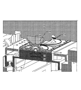
[0061] Figure 5 depicts a perspective view of a simplified portion of the
example
analysis unit of Figure 1 in a first configuration. Figure 6 depicts a detail
view of a portion of
Figure 5. In this first configuration, there is a gap between an optical
component 104 of the
optical sensor head 158 and the absorbent cleaning pad 120 of the optical
cleaning cartridge
110. In this example, the optical component has a concave surface 130, e.g.,
having a
negative radius of curvature that generally matches the radius of curvature
132 of the
domed shape of the optical cleaning assemblies 118. The optical cleaning
cartridge 110 may
12
CA 03067180 2019-12-11
WO 2019/199527 PCT/US2019/025397
be supported within the analysis unit 102 using a cartridge receiver 106,
which may support
the optical cleaning cartridge 110 from below.
[0062] Figure 7 depicts a perspective view of a simplified portion of
the example
analysis unit of Figure 1 in a second configuration. Figure 8 depicts a detail
view of a portion
of Figure 7.
[0063] During cleaning operations, the cartridge receiver 106 and the
optical sensor
head 158 may be moved into the second configuration, in which the absorbent
cleaning pad
120 may be brought into intimate contact with the optical component 104. While
in contact
with the optical component 104, the absorbent cleaning pad 120 and the optical
component
104 may be caused to move laterally relative to each other, e.g., in a figure-
8 or leminscate
pattern 164, a bowtie pattern 162, or in any other movement pattern that
causes the
absorbent cleaning pad 120 to wipe across the contaminated surface of the
optical
component 104.
[0064] Figure 9 depicts an example kit for an analysis unit that
includes the example
optical cleaning cartridge of Figure 1. The kit may also include, in some
implementations, a
container 156 of cleaning agent, e.g., IPA or other suitable liquid, and/or a
pipette 154 or
some other applicator, such as a syringe, for transferring a predefined amount
of the
cleaning agent to each optical cleaning assembly 118. In some implementations,
the kit may
only include the applicator or pipette 154 and the optical cleaning cartridge
110, with the
cleaning agent supplied separately, e.g., by an end user or facility where the
analysis unit
102 is located. In other implementations, the kit may include the container
156 with the
cleaning agent, but no applicator or pipette 154. In some such
implementations, the
container 156 for the cleaning agent may include a self-metering mechanism
that dispenses
only a predetermined amount of cleaning agent at a time. In other such
implementations,
the container 156 may be a simply container, with the user being responsible
for monitoring
the dispensation of cleaning agent to ensure that not too much cleaning agent
is dispensed.
In further implementations, the kit may include all three of the optical
cleaning cartridge
110, the applicator or pipette 154, and the container 156 of cleaning agent.
[0065] Prior to using an optical cleaning cartridge 110, the cleaning
agent, such as
IPA or other suitable liquid, may be applied to the absorbent cleaning pad
120, e.g., using
the pipette 154 or other applicator, such as a syringe. In some
implementations, the optical
cleaning cartridge 110 may include one or more features designed to allow for
confirmation
13
CA 03067180 2019-12-11
WO 2019/199527 PCT/US2019/025397
that the cleaning agent has been applied. For example, in some
implementations, the
optical cleaning cartridge may include a sensor, or components of a sensor,
that may be
used to detect if the cleaning agent has been applied. Figure 10 depicts
another exploded
view of the example optical cleaning cartridge of Figure 1 with various
examples sensors
included. In the example optical cleaning cartridge of Figure 10, a different
type of sensor is
implemented in each optical cleaning assembly 118 for the purposes of
facilitating
discussion. However, in practice, the same type of optical cleaning assembly
118 would, if
such sensors are used, likely be the same for each optical cleaning assembly
118 of an
optical cleaning cartridge 110.
[0066] In some instances, such a sensor may be as simple as a liquid
detection
sensor that may check for conductivity changes between two electrodes 172 in
an optical
cleaning assembly well that may simultaneously be in contact with liquid, such
as the
cleaning agent, if the liquid is present. A circuit may be configured to
monitor such
electrodes 172 and detect changes in conductivity between them that may result
from the
presence of a liquid bridge between them. Such electrodes 172 may be monitored
by a
circuit that resides on the optical cleaning cartridge 110 or may, for
example, simply be
conductive traces and/or wires that are routed to locations on the optical
cleaning cartridge
110 where they can interface with electrically conductive contacts of the
analysis unit 102
that may monitor the electrodes 172 for such changes in electrical
characteristics.
[0067] In other instances, the sensor may be more discriminating and may be
able to
detect not only the presence of a cleaning agent, but whether the cleaning
agent is the
desired cleaning agent. For example, an optical fiber 174 located in an
optical cleaning
assembly well 138 may be equipped with a particular optical coating that
swells when
exposed to IPA and changes its refractive index as a result; such refractive
index changes
.. may be detectable and may serve as a mechanism for determining that IPA is
present in the
optical cleaning assembly well 138. For example, a polycarbonate optical fiber
may be
coated (after removing any cladding layer) with a polystyrene layer, which may
swell when
exposed to alcohol. The analysis unit with which the optical cleaning
cartridge is used may
interrogate such optical fiber sensors to determine if the optical cleaning
cartridge 110 has
been properly prepared with cleaning agent such as IPA prior to initiating
cleaning
operations with the optical cleaning cartridge 110. If not, the analysis unit
102 may be
configured to display an error message and to refuse to initiate cleaning
operations.
14
CA 03067180 2019-12-11
WO 2019/199527 PCT/US2019/025397
[0068] In some other implementations, sensor for detecting the
application of the
cleaning agent may take the form of a chemical-based indicator 176 that may,
for example,
change color when exposed to the cleaning agent. Such a chemical indicator 176
may be
provided, for example, in portions of the absorbent cleaning pad near the base
of the
compliant support structure so that such chemicals are not proximate to the
top of the
compliant support structure 122 that will be used to apply pressure to the
absorbent
cleaning pad 120 that contacts the optical component (to prevent incidental
contamination
of the optical component with the indicator). In some implementations, the
cover plate 124
may include a port 182 that allows the indicator 176 to be seen if it would
otherwise be
obscured from view.
[0069] For example, potassium dichromate may undergo a reduction
reaction when
exposed to IPA that causes it to turn from a yellow color to a pale blue
color. Depending on
the cleaning agent selected, other chemical indicators could be used to
similar effect. Such
a color change may be observed by a human operator or may, in some cases, be
detected by
.. the analysis unit. For example, the analysis unit 102 may align the optical
sensor that is to
be cleaned with the portion of the optical cleaning cartridge 110 that has the
chemical
indicator 176 and may obtain image data that allows for the color of the
imaged region to
be identified¨if the color is not the expected color that would result from
the liquid
cleaning agent being present, then the analysis unit 102 may generate an error
message and
may require that the cleaning agent be added before continuing cleaning
operations.
[0070] In some instances, there may be no sensor used on the optical
cleaning
cartridge 110, but the analysis unit 102 may simply attempt to detect the
presence of a
liquid in the optical cleaning cartridge 110 using data from the optical
sensor. For example,
if the absorbent cleaning pad 120 includes a white or pale microfiber textile
layer 134 and a
darker-colored foam core 136, e.g., gray, dark gray, blue, dark blue, red,
etc., the exterior
textile layer 134 may appear much darker when wet due to the liquid acting as
a light pipe
to the darker foam core 136 (for example, when light-colored cloth gets wet,
it appears
darker and allows for darker colored objects beneath the cloth to be more
visible). In such
instances, the analysis unit 102 may obtain image data of the absorbent
cleaning pad 120
.. and compare the average color of the absorbent cleaning pad 120 against a
range of values
that have been predetermined to be indicative of the absorbent cleaning pad
120 being in a
"wet" state. If the absorbent cleaning pad 120 does not appear "wet" in view
of such
CA 03067180 2019-12-11
WO 2019/199527
PCT/US2019/025397
information, the analysis unit 102 may generate an error message and may
require that the
cleaning agent be added before continuing cleaning operations.
[0071] Alternatively, the imaging data from the optical sensor may be
analyzed to
determine the level of reflectivity that is present in the absorbent cleaning
pad 120; if the
absorbent cleaning pad 120 is wet, it will have a higher reflectivity than if
it is dry.
Accordingly, if the reflectivity of the absorbent cleaning pad is not within a
predetermined
range of reflectivity that is deemed to be indicative of a "wet" state, then
the analysis unit
102 may generate an error message and may require that the cleaning agent be
added
before continuing cleaning operations.
[0072] It will be understood that other cleaning cartridges and/or analysis
units may
be "open loop," i.e., they may have no provisions for detecting or indicating
the presence or
absence of a cleaning agent.
[0073] It will be understood that cleaning cartridges as discussed
herein may include
one or more optical cleaning assemblies. For example, a cleaning cartridge may
include
two, three, four, or even more optical cleaning assemblies. In such cases,
cleaning
operations may switch to unused optical cleaning assemblies at various stages
during
cleaning to ensure that contaminants wiped off of the optical component are
not re-
introduced to the optical component during later portions of the cleaning
operation. In
implementations with multiple optical cleaning assemblies, some or all of the
components
of each optical cleaning assembly may be integrated or consolidated into fewer
components. For example, a single cover plate may have three apertures in it
and be used
to secure parts for three optical cleaning assemblies. Similarly, a single
optical cleaning
assembly well may be sized large enough to receive multiple optical cleaning
assemblies.
Additionally or alternatively, a single, long absorbent cleaning pad may be
used for multiple
optical cleaning assemblies. In some implementations, the compliant support
structures for
multiple optical cleaning assemblies may be one contiguous component.
[0074] As noted earlier, in some implementations, the optical cleaning
cartridge 110
may include a re-use prevention mechanism 178, e.g., a radio-frequency
identification
(RFID) tag, a near-field communications (NFC) tag, a machine-readable serial
number, a bar
code, a quick response (QR) code, or other identifier that may be read by the
analysis unit
102 and used to identify the optical cleaning cartridge 110 in question and
determined if the
optical cleaning cartridge 110 should be used. For example, in some
implementations, the
16
CA 03067180 2019-12-11
WO 2019/199527
PCT/US2019/025397
analysis unit 102 may communicate such identifying information to a remote
server that is
communicatively connected with other analysis units 102, and the remote server
may
determine whether or not the optical cleaning cartridge 110 has been used
previously with
another analysis unit 102 (which would have also reported out that identifying
information
to the remote server during that earlier use). In other implementations, the
optical cleaning
cartridge 110 may include some form of memory, e.g., that may be part of an
RFID
component such as that shown in Figure 2, that allows usage data for the
optical cleaning
cartridge 110 to be stored in the optical cleaning cartridge 110 itself. Such
data may be read
by the analysis unit 102 to determine if the optical cleaning cartridge 110 is
unused; if
already used, the analysis unit 102 may refuse to re-use the optical cleaning
cartridge 110
and require that an unused replacement optical cleaning cartridge 110 be used.
In such
instances, when the analysis unit 102 performs cleaning operations using an
optical cleaning
cartridge 110, the analysis unit 102 may cause information stored in the
optical cleaning
cartridge 110 to be updated to reflect such usage and to prevent re-use later.
[0075] Figure 11 depicts an example process flow for using an optical
cleaning
cartridge such as those described herein. Various aspects of such a process
flow may be
caused to occur by a controller of the analysis unit, although some aspects of
the technique
may be performed by a user or another system.
[0076] In block 1102, an optical cleaning cartridge may be obtained.
In block 1104,
the optical cleaning cartridge may be dosed with a liquid cleaning agent, if
none is already
present. For example, a predetermined amount of IPA may be applied to each
optical
cleaning assembly using a pipette or similar applicator. In block 1106, the
optical cleaning
cartridge may be inserted into an analysis unit that is to have one or more
optical
components cleaned. Once the optical cleaning cartridge is inserted into the
analysis unit, a
cleaning mode may be initiated on the analysis unit in block 1108. In some
implementations, the analysis unit itself may be equipped with a cleaning
agent reservoir
and a system that is configured to dispense the cleaning agent into the
cartridge. In such
systems, the optical cleaning cartridge may be loaded into the analysis unit
first, and the
analysis unit may then deliver the cleaning agent to the appropriate optical
cleaning
assemblies.
[0077] In some implementations, the optical cleaning cartridge may be
pre-dosed
with a liquid cleaning agent, e.g., a metered amount of liquid cleaning agent
may be applied
17
CA 03067180 2019-12-11
WO 2019/199527
PCT/US2019/025397
to each absorbent cleaning pad prior to being packaged and shipped to a
customer. In such
implementations, the optical cleaning cartridge may be packaged in a sealed
wrapper, or
the optical cleaning assembly wells may be sealed with removable caps (plastic
or
elasomeric caps, for example, that may press-fit around the optical cleaning
assembly well
sidewalls), to prevent leakage and/or evaporation of the liquid cleaning
agent. Prior to use,
the wrapper or caps may be removed by the user. In some such instances, the
wrapper or
caps may be colored or patterned in a manner that makes it easy to visually
confirm if the
wrapper or caps have been removed, e.g., the caps may be made from a red,
orange, black,
blue, or green material that has high contrast with a white or off-white
material used for the
absorbent cleaning pads. In some such implementations, the analysis unit
itself may scan or
image the absorbent cleaning pads prior to use to confirm that the wrapper or
cap has been
entirely removed¨detection of any region that still has the high-contrast
color, for
example, may indicate that the wrapper or cap has not been completely removed.
The
analysis unit may halt operations and indicate that the optical cleaning
cartridge has not
.. been properly configured for use.
[0078] Figure 12 depicts a cross-section of an example optical
cleaning cartridge
insert with a sealing cap. The insert 116 is similar to that shown in Figure
4', and similar
callouts are used to indicate similar structures (some components are omitted
from what is
shown in Figure 4', however). The cover plate 124 is different in shape from
that in Figure
4', but serves a similar function. An elastomeric or plastic cap 188 is shown
that seals
around the optical cleaning assembly well 138, sealing against the sidewalls
of the optical
cleaning assembly well 138. The cap 188 may be sealed to the optical cleaning
assembly
well 138 after the absorbent cleaning pad 120 is dosed with liquid cleaning
agent, thereby
sealing the liquid cleaning agent inside and preventing leakage. Prior to use,
the cap 188
.. may be removed.
[0079] Figure 13 depicts a cross-section of an example optical
cleaning cartridge
insert with a sealing membrane. This example is similar to that of Figure 12,
except that a
plastic membrane or wrapper 190 has been applied over the absorbent cleaning
pad 120
(after the absorbent cleaning pad 120 has been dosed with liquid cleaning
agent) and
adhered or glued to the walls that form the perimeter of the optical cleaning
assembly well
138. A tab 192 of the membrane or wrapper 190 may extend beyond the edge of
the
18
CA 03067180 2019-12-11
WO 2019/199527
PCT/US2019/025397
optical cleaning assembly well 138 to allow a user to easily peel the membrane
or wrapper
190 off of the optical cleaning cartridge.
[0080] As part of the cleaning mode, the analysis unit may,
optionally, check in block
1110 to see if the optical cleaning cartridge has been previously used, as
discussed earlier
herein. If it is determined by the analysis unit in block 1110 that the
optical cleaning
cartridge has been previously used, then the analysis unit may stop the
cleaning mode in
block 1112 and the optical cleaning cartridge may be removed from the analysis
unit in
block 1114 before being replaced by a new optical cleaning cartridge in block
1116 which
may then be inserted into the analysis unit in block 1106, at which point the
cleaning mode
of the analysis unit may be restarted.
[0081] If it is determined in block 1110 that the optical cleaning
cartridge has not
been previously used (or if no check for previous use of the optical cleaning
cartridge is
performed at all), the technique may optionally proceed to block 1118, in
which the analysis
unit may check, using one of the techniques or technologies discussed earlier
herein,
whether or not cleaning agent is present in the optical cleaning cartridge. If
it is determined
in block 1118 that the cleaning agent is not present, the analysis unit may
stop the cleaning
mode in block 1120 and the optical cleaning cartridge may be removed from the
analysis
unit in block 1122, after which the cleaning agent may be applied to the
optical cleaning
cartridge in block 1124 before the optical cleaning cartridge is re-inserted
into the analysis
unit in block 1106, at which point the cleaning mode of the analysis unit may
be restarted.
[0082] If it is determined in block 1118 that there is cleaning agent
in the optical
cleaning cartridge (or if no check for cleaning agent is performed at all),
the technique may
proceed to block 1126, in which the analysis unit may cause an absorbent
cleaning pad of
the optical cleaning cartridge to come into contact with an optical component
to be
cleaned. This may involve translating the optical cleaning cartridge and/or
the optical
component horizontally (in the X and/or Y directions) so that the absorbent
cleaning pad is
generally centered underneath the optical component, and then translating the
optical
cleaning cartridge and/or the optical component vertically (in the Z
direction) so that the
absorbent cleaning pad and the optical component come into contact.
[0083] The analysis unit may then, in block 1128, cause the absorbent
cleaning pad
to be translated laterally, e.g., in a lemniscate pattern, bowtie pattern, or
other pattern, one
or more times to cause the absorbent cleaning pad to be wiped across the
optical
19
CA 03067180 2019-12-11
WO 2019/199527 PCT/US2019/025397
component while being compressed against the optical component by the
compliant
support structure.
[0084] In some implementations, the cleanliness of the optical
component may be
optionally evaluated in block 1130 to determine the effectiveness of a
cleaning operation.
For example, the optical cleaning cartridge and/or optical component may be
moved so that
opticla cleaning cartridge is not blocking the optical path of the optical
component and the
optical component may therefore be used to perform a test measurement in which
the
transmissivity of the optical component may be evaluated under one or more
conditions.
[0085] In block 1132, a determination may be made as to whether
further cleaning is
desired. Such a determination may be made based on the results of a
cleanliness
evaluation, as discussed with respect to block 1130, or may be made based on a
predetermined cleaning schedule. For example, if an optical cleaning cartridge
has three
optical cleaning assemblies, a separate cleaning cycle may be performed with
each optical
cleaning assembly (an initial cleaning cycle, an intermediate cleaning cycle,
and a final
cleaning cycle), regardless of the cleanliness level of the optical component.
If multiple
optical cleaning assemblies are present on the optical cleaning cartridge,
then the analysis
unit may periodically translate the optical component and the optical cleaning
cartridge
relative to one another so as to engage the absorbent cleaning pad of one of
the other
optical cleaning assemblies with the optical component, and so forth. If it is
determined in
block 1132 that further cleaning is to be performed, then the technique may
return to block
1126, at which point the analysis unit may cause the same, or a different,
optical cleaning
assembly of the optical cleaning cartridge to be centered under the optical
component
before proceeding to block 1128.
[0086] If it is determined in block 1132 that no further cleaning
operations are
needed, the analysis unit may stop the cleaning mode and the optical cleaning
cartridge
may be removed, thereby allowing the analysis unit to return to normal use.
[0087] Optical cleaning cartridges such as those discussed herein were
found to
offer vastly superior and repeatable cleaning performance as compared with
manual
cleaning, especially in systems in which the optical components could only
feasibly be
cleaned manually using a "blind" cleaning technique. For example, in many
analysis
systems, it is difficult or impossible for a user to actually directly inspect
the outermost
surface of the optical components, as such surfaces may frequently be located
inside the
CA 03067180 2019-12-11
WO 2019/199527 PCT/US2019/025397
analysis unit in a location that does not have sufficient clearance for the
user's head.
Moreover, there may not even be sufficient clearance or access for a user to
inspect such
surfaces even indirectly, e.g., using a mirror or other device. In such
instances, the user may
need to resort to "blind" cleaning, where they must work by touch or otherwise
without
direct visual confirmation to clean the optical components. Such cleaning
operations may
be highly susceptible to variation in efficacy since the process is manual,
and may vary from
user to user or even between different attempts of the same user. To
illustrate the contrast
between blind cleaning and optical cleaning cartridge-based cleaning,
photographs of
optical components after manual blind cleaning and after cleaning with an
optical cleaning
cartridge are discussed below.
[0088] Figure 14 is a magnified photograph of a contaminated example
optical
component after two blind manual cleaning passes. As can be seen, streaks of
lighter-
colored residue or contaminants 1452 remain on the lens even after two passes
of manual
cleaning.
[0089] Figure 15 is a magnified photograph of a contaminated example
optical
component after blind manual cleaning passes (using, for example, an absorbent
cleaning
pad supported by a technician's finger and wetted with IPA) that resulted in
an additional
2% intensity loss through the optical component. In this example, two passes
of manual
cleaning actually exacerbated the contamination problem, as the contaminants
1452 were
smeared across a larger area of the optical component. While some of the
contaminant was
removed, thereby improving transmissivity of the optical component in those
areas, other
areas of the optical component that were not previously contaminated had
contaminant
transferred to them, resulting in an actual 2% further decrease in signal
strength through
the optical component. The 2% degradation discussed above is, of course,
simply the result
of one example cleaning done by a particular individual; other cleanings done
by the same
individual or other individuals may exhibit more or less degradation.
[0090] Figure 16 is a magnified photograph of a contaminated example
optical
component after cleaning using the example optical cleaning cartridge of
Figure 1. In
contrast to the lenses shown in Figures 14 and 15, the lens in Figure 16 has
been cleaned
using an optical cleaning cartridge such as the optical cleaning cartridge 110
(with IPA as the
cleaning agent) and techniques such as those discussed above. As can be seen,
the surface
21
of the optical component is almost or entirely completely free of
contaminants, in stark
contrast to the results of the manual blind cleaning operations.
[0091] It is to be understood that the phrase "for each <item> of the
one or more
<items>," if used herein, should be understood to be inclusive of both a
single-item group
and multiple-item groups, i.e., the phrase "for ... each" is used in the sense
that it is used in
programming languages to refer to each item of whatever population of items is
referenced.
For example, if the population of items referenced is a single item, then
"each" would refer
to only that single item (despite the fact that dictionary definitions of
"each" frequently
define the term to refer to "every one of two or more things") and would not
imply that
there must be at least two of those items.
[0092] The use, if any, of ordinal indicators, e.g., (a), (b), (c)...
or the like, in this
disclosure and claims is to be understood as not conveying any particular
order or sequence,
except to the extent that such an order or sequence is explicitly indicated.
For example, if
there are three steps labeled (i), (ii), and (iii), it is to be understood
that these steps may be
performed in any order (or even concurrently, if not otherwise
contraindicated) unless
indicated otherwise. For example, if step (ii) involves the handling of an
element that is
created in step (i), then step (ii) may be viewed as happening at some point
after step (i).
Similarly, if step (i) involves the handling of an element that is created in
step (ii), the
reverse is to be understood.
[0093] Terms such as "about," "approximately," "substantially," "nominal,"
or the
like, when used in reference to quantities or similar quantifiable properties,
are to be
understood to be inclusive of values within 10% of the values or relationship
specified (as
well as inclusive of the actual values or relationship specified), unless
otherwise indicated.
[0094] It should be appreciated that all combinations of the foregoing
concepts
(provided such concepts are not mutually inconsistent) are contemplated as
being part of
the inventive subject matter disclosed herein. In particular, all combinations
of claimed
subject matter appearing at the end of this disclosure are contemplated as
being part of the
inventive subject matter disclosed herein. It should also be appreciated that
terminology
explicitly employed herein
should be accorded a meaning most consistent with the particular concepts
disclosed
herein.
22
Date Recue/Date Received 2021-06-09
CA 03067180 2019-12-11
WO 2019/199527
PCT/US2019/025397
[0095] It is to
be further understood that the above disclosure, while focusing on a
particular example implementation or implementations, is not limited to only
the discussed
example, but may also apply to similar variants and mechanisms as well, and
such similar
variants and mechanisms are also considered to be within the scope of this
disclosure.
23