Note: Descriptions are shown in the official language in which they were submitted.
CA 03067252 2019-12-13
WO 2019/018877 PCT/AU2018/050487
Tonsillectomy suction dissector apparatus
Field of the Invention
[1] This invention relates generally to tonsillectomy apparatus. More
particularly, this invention
relates to tonsillectomy apparatus selectively configurable between dissection
and suction and
suction only modes of use.
Background of the Invention
[2] Tonsillectomy is a surgical procedure in which both palatine tonsils
are removed from a recess
in the side of the pharynx called the tonsillar fossa.
[3] One type of tonsillectomy procedure comprises the use of an elongate
cutting blade for the
dissection of the tonsils, typically held in one hand whilst another hand uses
forceps to hold the tonsils.
[4] A vacuum suction tip may be used to remove fluids (blood and saliva)
during the procedure.
The Yankauer tip (tonsil tip) is one of the most commonly used suction tips.
[5] However, the utilisation of three instruments requires an assistant or
alternatively the
substitution of instrumentation as required, complicating and prolonging the
procedure.
[6] Furthermore, whilst the Yankauer tip allows for aspiration of large
volumes of fluid, the
Yankauer tip has the disadvantage of easily occluding when the tip is brought
into close approximation
with tissues or large blood clots. Surgeons often place a gauze sponge over
the tip and suctioning fluid
through the gauze to prevent occluding clogging.
[7] The present invention seeks to provide a tonsillectomy suction
dissector apparatus, which will
overcome or substantially ameliorate at least some of the deficiencies of the
prior art, or to at least
provide an alternative.
[8] It is to be understood that, if any prior art information is referred
to herein, such reference
does not constitute an admission that the information forms part of the common
general knowledge
in the art, in Australia or any other country.
Summary of the Disclosure
[9] There is provided herein a tonsillectomy suction dissector apparatus
comprising a proximal
handle and a distal curved tip. The apparatus comprises a suction channel
within and along the tip
operably connecting at least one suction inlet port located at the end of the
tip to a vacuum port of
the handle for the suction of fluid in use. The apparatus further comprises a
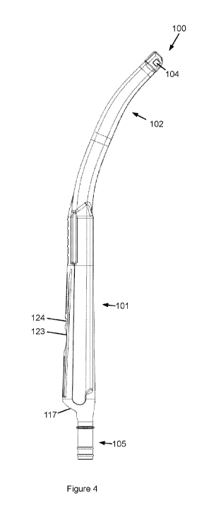
flexible cutting blade
member slidably retained and orientated widthwise within a corresponding
widthwise and lengthwise
slot along the tip and configurable by hand operable locking mechanism between
an extended
position wherein a distal cutting end of the cutting blade member extends from
the end of the tip and
1
CA 03067252 2019-12-13
WO 2019/018877
PCT/AU2018/050487
a retracted position wherein the distal cutting end of the flexible cutting
blade member is retracted
within an end of the tip.
[10] This retraction and extension of the blade allows dual functionality
as suction tip or suction
dissector, thus speeding the operation and reducing blood loss.
[11] As such, the locking mechanism may be used for quickly reconfiguring
the apparatus between
dissection and suction and suction only modes of operation. Furthermore, the
present configuration
allows for one-handed dissection and suctioning, freeing the other hand for
other tasks, such as
manipulating forceps.
[12] Furthermore, the present locking mechanism may allow for the
reconfiguration of the
apparatus with one hand, such as using the thumb only, freeing the forefingers
for gripping the handle.
[13] Specifically, the locking mechanism may comprise the flexible cutting
blade member
comprising a locking lever which locks within superior apertures of the
handle. The cutting blade
member extends from a rear aperture of the handle for pushing forwards to the
extended position
wherein the locking lever locks within the superior apertures. Furthermore,
the locking lever is
accessible via the superior apertures to disconnect and pull the lever
rearwardly to retract the cutting
blade member.
[14] The position of the suction holes towards the tonsillar fossa, where
the bleeding happens,
allowed instant suction of the blood at the exactly bleeding point, thus
minimising the chance of blood
accumulating in the throat, reducing risk of blood/clot inhalation.
[15] Also, the position of the blade towards the surgeon, allows precise
dissection and full visibility
of the cutting place at all time, reducing the chance of inadvertently
injuring surrounding tissues, and
causing further bleeding
[16] Furthermore, the configuration of the suction inlet ports may
substantially reduce or
eliminate occlusion problems as may be experienced by the Yankauer tip.
Specifically, the suction inlet
ports may be located inferiorly with respect to the distal cutting end and may
be arranged on differing
faces of the end of the tip so as to prevent occlusion by pressing against one
surface thereof.
Specifically, in embodiments, the suction inlet ports may comprise a pair of
distally located, oppositely
laterally located and inferiorly located suction inlet ports.
[17] According to one aspect, there is provided a tonsillectomy suction
dissector apparatus
comprising a proximal handle and a distal curved tip; a suction channel within
and along the tip
operably connecting at least one suction inlet port located at the end of the
tip to a vacuum port at
the handle; and a flexible cutting blade member slidably retained within a
slot within and along the
tip and configurable by a hand operable locking mechanism between an extended
position wherein a
distal cutting end of the flexible cutting blade member extends from the end
of the tip and a retracted
2
CA 03067252 2019-12-13
WO 2019/018877
PCT/AU2018/050487
position wherein the distal cutting end of the flexible cutting blade member
is retracted within the
end of the tip.
[18] The flexible cutting blade member may comprise a flattened portion
flexibly orientated
widthwise within the slot.
[19] The flexible cutting blade member may comprise plastic.
[20] The flexible cutting blade member may comprise a thickness of
approximately 3 mm.
[21] The flexible cutting blade member may comprise a width of
approximately 10 mm.
[22] The apparatus may comprise a two-piece construction comprising a first
piece comprising the
integrally formed handle and tip and a second piece comprising the cutting
blade member.
[23] The slot and the cutting blade member may be configured for the
rearward removal of the
cutting blade member.
[24] The distal cutting end may narrow towards an orthogonal straight
cutting edge.
[25] The cutting edge may comprise a length of approximately 10 mm.
[26] The cutting edge may comprise serrations.
[27] The serrations may be arranged substantially along the width of the
cutting edge and
transition from top to bottom of the edge.
[28] The cutting edge may not be sharpened to a point.
[29] The cutting edge may comprise a width of approximately 1 mm.
[30] The at least one suction inlet port may located inferiorly with
respect to the distal cutting end.
[31] The at least one suction inlet port may comprise a plurality of
suction inlet ports comprising
at least one of distally, laterally and inferiorly located suction inlet
ports.
[32] The at least one suction inlet port may comprise a plurality of
suction inlet ports comprising
distally, laterally and inferiorly located suction inlet ports.
[33] The distally located suction inlet ports may comprise a pair of
laterally adjacent suction inlet
ports.
[34] The handle may comprise a noncircular cross-section along the elongate
axis of the handle.
[35] The handle may comprise at least one of planar lateral and inferior
surfaces.
[36] The vacuum tube connection extends from a proximal end of the handle.
[37] The vacuum tube connection may cylindrical and orientated
substantially parallel to a
lengthwise axis of the handle.
[38] The locking mechanism may comprise the cutting blade member comprising
a locking lever
depressable via a superior aperture within the handle.
3
CA 03067252 2019-12-13
WO 2019/018877
PCT/AU2018/050487
[39] The proximal end of the cutting blade member extends via a rearward
aperture of the handle
and wherein the proximal end may configured for pushing forwardly to slide the
cutting blade member
forwardly.
[40] The lever may comprise an arrowhead boss able to slide underneath and
intermediate portion
and locate within a forward aperture.
[41] A rearward edge of the arrowhead boss may lock against a forward edge
of the intermediate
portion to retain the cutting blade member in the extended position.
[42] The lever may be depressable via the aperture to disengage the
arrowhead boss from the
intermediate portion.
[43] The lever may comprise a rearward knob having a forward facing edge
for pulling the lever
rearwardly.
[44] There may also provided a method of performing a tonsillectomy
comprising an apparatus as
claimed in claim 1, the method comprising, with one hand, extending the
cutting blade member
forwardly to perform simultaneous dissection and suction and retracting the
cutting blade member to
perform suction only.
[45] Other aspects of the invention are also disclosed.
Brief Description of the Drawings
[46] Notwithstanding any other forms which may fall within the scope of the
present invention,
preferred embodiments of the disclosure will now be described, by way of
example only, with
reference to the accompanying drawings in which:
[47] Figure 1 shows a top perspective view of a tonsillectomy suction
dissector apparatus in
accordance with embodiments;
[48] Figure 2 illustrates a bottom perspective view of the apparatus;
[49] Figure 3 illustrates a top plan view of the apparatus;
[50] Figure 4 illustrates a side elevation view of the apparatus;
[51] Figure 5 shows a front elevation view of the apparatus;
[52] Figure 6 shows a rear elevation view of the apparatus;
[53] Figure 7 shows a top perspective view of an end of the suction tip of
the apparatus;
[54] Figure 8 illustrates a bottom plan view of the end of the suction tip;
[55] Figure 9 illustrates a front elevation view of the end of the suction
cup;
[56] Figure 10 illustrates a cross-sectional view of the tip of the
apparatus;
[57] Figure 11 illustrates a cross-sectional side view of the end of the
tip of the apparatus;
[58] Figure 12 illustrates a cross-sectional view of the handle of the
apparatus;
4
CA 03067252 2019-12-13
WO 2019/018877
PCT/AU2018/050487
[59] Figure 13 illustrates the rearward position of the cutting blade
member in the retracted
position; and
[60] Figure 14 illustrates the forward position of the cutting blade member
in the extended
position.
Description of Embodiments
[61] A tonsillectomy suction dissector apparatus 100 comprises a proximal
handle 101 and a distal
curved tip 102. The apparatus 100 comprises at least one suction channel 103
operably connecting at
least one suction inlet port 104 located at an end of the tip 102 and a vacuum
tube connection 105
located at the handle 101.
[62] Reference will be made herein to the orientational axes provided in
Figure 1 wherein the
apparatus 100 is elongate comprising a near/proximal and a far/distal end,
side/lateral sides and
top/superior and bottom/inferior sides.
[63] The apparatus 100 further comprises a flexible cutting blade member
106 slidably retained
within a slot 107 along the tip 102 and configurable by hand operable locking
mechanism 108 at the
handle 101 between an extended position wherein a distal cutting end 109 of
the cutting blade
member 106 protrudes from the end of the tip 102 as is substantially
represented in Figures 7, 8 and
11, and a retracted position wherein the distal cutting end 109 is retracted
within the end of the tip
102.
[64] Utilisation of the apparatus 100 comprises the connection of suction
apparatus to the vacuum
tube connection 105. The curved tip 102 is then inserted from a left or right
side into the mouth such
that the end thereof locates at the back of the throat. The locking mechanism
108 may be configured
to extend the distal cutting end 109 of the cutting blade member 106 from the
end of the tip 102 such
that the distal cutting end 109 is able to dissect the respective tonsil,
typically whilst being pulled with
a pair of forceps on the opposite hand. The distal cutting end 109 defines an
orthogonal straight
cutting edge 115 which may be pushed forwardly against the base of the tonsil
while the tonsil is
pulled in the opposite direction of the forceps, thereby dissecting the
tonsil.
[65] While dissecting, fluids may be drained through the suction inlet
ports 104. At any time, the
surgeon may employ the locking mechanism 108 to retract the distal cutting end
109 to employ the
tip 102 for suction alone, extending the distal cutting end 109 when and as
required.
[66] The procedure may be repeated for the opposite tonsil by inserting the
curved tip 102 from
the opposite lateral side of the mouth.
[67] In a preferred embodiment, the handle 101 and the tip 102 are
integrally formed from plastic.
Furthermore, so too in embodiments is the cutting blade member 106 made from
plastic. However,
CA 03067252 2019-12-13
WO 2019/018877
PCT/AU2018/050487
in embodiments, the cutting blade member 106 may be flexibly formed from metal
so as to be
electrically conductive for electrocautery application. This will allow triple
functionality as suction,
dissection and electro cautery, and instantly sealing the bleeding points.
Also, employing electric
coagulation in the instrument will reduce the need of using force to dissect
scarred tonsils as the
electricity will dissolve scar tissue, coagulate while minimal dissection
force is applied, leading to more
precise dissection, less tissue trauma, thus quicker and less painful healing
post operatively.
[68] With reference to Figure 4, the handle 102 may be generally elongate,
thereby having an
elongate axis and the tip 102 may curve from substantially in-line with the
elongate axis of the handle
101 to deviate by approximately 40 therefrom at a distal end thereof. This 40
curvature, takes away
the surgeons hands outside the operating field ensuring constant visibility,
at the same time 40
smooth curvature maintained adequate suction power inside the suction port and
prevent the blood
clogging inside the suction port.
[69] With reference to Figures 1 and 2, the vacuum connection port 105 may
extend from a
proximal end of the handle 102. In the embodiment shown, the vacuum connection
port 105 is
generally cylindrical comprising an elongate axis substantially in line with
an elongate axis of the
handle 101. The vacuum connection port 105 may comprise connection interlock
annuli 112 and 0-
ring seal 113.
[70] Figure 7 illustrates the end of the tip 102 in further detail showing
the cutting blade member
106 in the extended position.
[71] In a preferred embodiment shown, the cutting blade member 109 has a
section which is
flattened and orientated widthwise within the lengthwise slot 107 so as to be
able to flex within the
slot 107 when transitioning between the extended and retracted position. In
one embodiment, the
cutting blade member 109 may comprise a width of approximately 10 millimetres
and a thickness of
approximately 2 mm
[72] In a preferred embodiment, the cutting blade member 106 is
manufactured from plastic.
[73] As is illustrated in figure 7, the distal cutting end 109 may narrow
to the orthogonal straight
cutting edge 115.
[74] Furthermore, the cutting edge 115 may comprise a plurality of
serrations 116 running
orthogonally across the cutting edge 115 from top to bottom which may engage
the tonsil tissue to
substantially prevent the cutting blade member 106 from slipping sideways
during dissection and
avoiding surrounding tissue damage.
[75] As is best illustrated in Figure 11, the cutting edge 115 is not
sharpened to a point, thereby
limiting the effectiveness of the cutting action thereof which may undesirably
inadvertently damage
surrounding tissue during manipulation, whilst yet comprising sufficient
narrowness for being able to
6
CA 03067252 2019-12-13
WO 2019/018877
PCT/AU2018/050487
effectively cut the tonsils when required. For example, the width of the
cutting edge 115 may be
approximately 1 mm. Also, the blade dimensions are optimised to be big enough
to dissect well, but
small enough to maintain visibility, watching the surrounding tissues at all
time to avoid collateral
tissue damage.
[76] With reference to Figure 8, there is shown the distal cutting end 109
extending beyond the
end of the tip 102 by approximately 5 mm in the extended position.
[77] With reference to Figure 7, there is illustrated the suction inlet
ports 104 being located
inferiorly with respect to the cutting blade member 106.
[78] Furthermore, in a preferred embodiment, the suction inlet ports 104
may be located on
multiple faces of the end of the tip 102 such as distally, laterally and
inferiorly, thereby reducing
likelihood of occlusion. Specifically, Figure 7 shows the suction inlet ports
comprising a pair of distal
inlet ports 104A, a pair of opposite lateral suction inlet ports 10413 and
Figure 8 shows an inferior inlet
port 104C.
[79] Figure 12 illustrates a cross-sectional view of the apparatus 100
showing the locking
mechanism 100 in further detail. As is shown, the cutting blade member 106 may
comprise a proximal
end 116 extending from a rearward aperture 117 of the handle 102. A proximal
face of the proximal
end 116 is angled so as to occupy and mate flush with the proximal surface 118
of the handle 102
when located forwardly.
[80] The cutting blade member 106 further comprises a locking lever 119
pivotally coupled to an
adjacent portion 120 by way of live hinge 121. Furthermore, a superior side
122 of the handle 102
comprises a major rearward aperture 123 and a minor forward aperture 124
between which an
arrowhead boss 125 of the lever 119 is able to selectively transition. The
lever 119 comprises a
rearward knob 126 accessible via the major aperture 123 to depress the lever
119. Furthermore, the
lever 119 terminates distally with buttress 127 which abuts against opposing
wall 128 when the cutting
blade member 106 is in the extended position.
[81] Figure 12 shows the cutting blade member 106 in the retracted
configuration. As such, in
order to extend the cutting blade member 109 for dissection, the rearward end
116 may be pushed
forwardly along the elongate axis of the handle 102, typically with the thumb
whilst grasping the
underneath of the handle 102 with the forefingers. The forward ramp 129 of the
arrowhead boss 125
depresses the lever 109 such that the arrowhead boss 125 is able to transition
under the intermediate
portion 130 between the major and minor apertures 123, 124 until such time
that the arrowhead boss
125 locates within the forward minor aperture 124. Once in this location, the
rearward orthogonal
edge 130 of the arrowhead boss 125 jambs against a forward edge 131 of the
intermediate portion
130, preventing the cutting blade member 106 from sliding rearwardly under
pressure. At this
7
CA 03067252 2019-12-13
WO 2019/018877 PCT/AU2018/050487
extended position, the buttress 127 may abut against the opposing wall 128
thereby limiting the
forward travel of the rearward end 116.
[82] Subsequently, in order to retract the cutting blade member 106, the
thumb may be inserted
within the major aperture 123 to substantially depress the lever 119 and to
simultaneously pull
rearwardly against the forward edge 132 of the knob 126 which disengages the
rearward face 130 of
the arrowhead boss 125 from the forward edge 131 of the intermediate portion
130 and allowing the
rearward sliding of the cutting blade member 106 under action of the thumb.
[83] Act As can also be appreciated from Figure 12, a rearward portion 133
of the slot 107 is
sufficiently wide and so as to allow the entire rearward removal of the
cutting blade member 106.
[84] Whilst the locking mechanism 108 may be configured for thumb
operation, the handle 102
may be shaped for enhancing the grip of the opposing forefingers.
Specifically, with reference to figure
5, the panel 102 may comprise planar side walls and orthogonal inferior edges
111, conferring a non-
circular cross-section to the handle 102, thereby preventing or reducing
rotational slipping thereof
within the surgeon's hand.
[85] The foregoing description, for purposes of explanation, used specific
nomenclature to provide
a thorough understanding of the invention. However, it will be apparent to one
skilled in the art that
specific details are not required in order to practice the invention. Thus,
the foregoing descriptions of
specific embodiments of the invention are presented for purposes of
illustration and description. They
are not intended to be exhaustive or to limit the invention to the precise
forms disclosed; obviously,
many modifications and variations are possible in view of the above teachings.
The embodiments were
chosen and described in order to best explain the principles of the invention
and its practical
applications, they thereby enable others skilled in the art to best utilize
the invention and various
embodiments with various modifications as are suited to the particular use
contemplated. It is
intended that the following claims and their equivalents define the scope of
the invention.
8