Note: Descriptions are shown in the official language in which they were submitted.
SYSTEM AND METHOD FOR NONINVASIVE
ANALYSIS OF SUBCUTANEOUS TISSUE
FIELD OF THE INVENTION
The present invention relates to noninvasive analysis. More particularly, the
present
invention relates to a system and method for noninvasive analysis of
subcutaneous tissue.
BACKGROUND OF THE INVENTION
Various medical conditions are characterized by accumulation of liquids under
or behind
the skin surface. Such conditions may include otitis media, pressure ulcers,
or other types
of deep tissue injury under intact skin.
Medications or other substances may be introduced or delivered into the
bloodstream. For
example, a substance may be delivered orally to a patient, or may be injected
into tissue or
via an intravenous infusion. In some cases, it is important to monitor the
concentration or
amount of the substance in a patient's blood or tissue. Monitoring the
concentration or the
amount may include drawing a blood or tissue sample from the patient.
SUMMARY OF THE INVENTION
There is thus provided, in accordance with some embodiments of the present
invention, a
method for noninvasive analysis of tissue, the method including: irradiating a
surface of
the tissue with short wave infrared (SWIR) radiation in a first spectral band
that is strongly
absorbed by water, and with SWIR radiation in a second spectral band such that
an
interaction of the radiation in both spectral bands with a component of the
tissue other than
water is substantially identical; measuring an intensity of the radiation that
emerges from
the tissue in each of the spectral bands; calculating a relative absorption by
the tissue of
radiation in one of spectral bands relative to absorption by the tissue of
radiation in the
other of the spectral bands; and determining a state of the tissue in
accordance with the
calculated relative absorption.
Furthermore, in accordance with some embodiments of the present invention, the
first
spectral band is in the wavelength range of 1400 nm to 1500 nm.
1
Date Recue/Date Received 2020-10-07
Furthermore, in accordance with some embodiments of the present invention, the
second
spectral band is in the wavelength range of 1000 nm to 1350 nm or 1500 nm to
2100 nm.
Furthermore, in accordance with some embodiments of the present invention, a
gap in
wavelength between the first and second spectral bands is less than 200 nm.
Furthermore, in accordance with some embodiments of the present invention,
measuring
the intensity includes measuring the intensity of the radiation that is
transmitted across the
tissue (e.g., passing through the tissue and not reflected back towards the
radiation source).
Furthermore, in accordance with some embodiments of the present invention, the
tissue
includes tissue of a finger or an ear.
Furthermore, in accordance with some embodiments of the present invention,
measuring
the intensity includes measuring the intensity of the radiation that is
reflected by the tissue.
Furthermore, in accordance with some embodiments of the present invention,
measuring
the intensity includes measuring the intensity of the radiation that emerges
from the tissue
at a plurality of lateral distances from a location of the irradiating of the
tissue.
.. Furthermore, in accordance with some embodiments of the present invention,
the state of
the tissue includes a concentration of a substance in blood.
Furthermore, in accordance with some embodiments of the present invention, the
substance is an introduced substance.
There is further provided, in accordance with some embodiments of the present
invention,
a system for noninvasive analysis of tissue, the system including: at least
one source of
infrared radiation to irradiate the tissue, the infrared radiation including
SWIR radiation in
a first spectral band that is strongly absorbed by water, and including
radiation in a second
spectral band such that an interaction of the radiation in both spectral bands
with a
component of the tissue other than water is substantially identical; at least
one radiation
detector to measure an intensity of radiation in each of the two spectral
bands that emerges
from the tissue(e.g., reflected from the tissue or passing through the tissue,
to come out at
another side); and a processor that is configured to calculate a relative
absorption by the
tissue of radiation in one of spectral bands relative to absorption by the
tissue of radiation
2
Date Recue/Date Received 2020-10-07
in the other of the spectral bands and determine a state of the tissue in
accordance with the
calculated relative absorption.
Furthermore, in accordance with some embodiments of the present invention,
wherein the
at least one radiation detector is configured to measure the intensity of the
radiation that
emerges from a surface of the tissue that is irradiated by the at least one
radiation source.
Furthermore, in accordance with some embodiments of the present invention, the
at least
one radiation detector is configured to measure the intensity of the radiation
that emerges
from the surface of the tissue at a plurality of lateral distances from the at
least one
radiation source.
Furthermore, in accordance with some embodiments of the present invention, the
at least
one radiation detector comprises a plurality of radiation detectors separated
by different
lateral distances from the at least one radiation source.
Furthermore, in accordance with some embodiments of the present invention, the
at least
one radiation detector is configured to measure the radiation that emerges
from a surface
of the tissue that is substantially opposite a surface of the tissue that is
irradiated by the at
least one radiation source.
Furthermore, in accordance with some embodiments of the present invention, the
system
includes a removable cover for placement over an aperture of the at least one
radiation
source or of the at least one radiation detector.
Furthermore, in accordance with some embodiments of the present invention, the
at least
one radiation source includes two radiation sources, one of the sources being
configured to
emit radiation in the first spectral band and the other being configured to
emit radiation in
the second spectral band.
Furthermore, in accordance with some embodiments of the present invention, the
at least
one radiation detector includes two radiation detectors, one of the detectors
being
configured to measure an intensity of radiation in the first spectral band and
the other
being configured to measure an intensity of radiation in the second spectral
band.
Furthermore, in accordance with some embodiments of the present invention, the
system
includes a dispersive element to separate spectral components of the infrared
radiation and
3
Date Recue/Date Received 2020-10-07
a micro-mirror array, the micro-mirror array being operable to direct a
selected spectral
component of the infrared radiation to the tissue or to the at least one
radiation detector.
Furthermore, in accordance with some embodiments of the present invention, the
first
spectral band is in the wavelength range of 1400 nm to 1500 nm.
Furthermore, in accordance with some embodiments of the present invention, the
second
spectral band is in the wavelength range of 1000 nm to 1350 nm or 1500 nm to
2100 nm.
There is further provided, in accordance with some embodiments of the present
invention,
a method for determining a state of tissue, the method including: irradiating
a surface of
the tissue with SWIR radiation in a first spectral band in the wavelength
range 1300 nm to
1430 nm, and with SWIR radiation in a second spectral band such that an
interaction of
the radiation in both spectral bands with a component of the tissue other than
water is
substantially identical; measuring an intensity of the radiation that emerges
from the tissue
in each of the spectral bands; and calculating an absorption by the tissue of
radiation in the
two spectral bands, the absorption being indicative of the state of the
tissue.
BRIEF DESCRIPTION OF THE DRAWINGS
In order for the present invention to be better understood and for its
practical applications
to be appreciated, the following Figures are provided and referenced
hereafter. It should be
noted that the Figures are given as examples only and in no way limit the
scope of the
invention. Like components are denoted by like reference numerals.
Fig. 1A is a schematic drawing of a system for noninvasive analysis of
subcutaneous
liquids based on reflection of infrared radiation, in accordance with an
embodiment of the
present invention.
Fig. 1B is a schematic illustration of a plurality of component apertures of
an optical head
of the system shown in Fig. 1A.
Fig. 2A is a schematic drawing of a measurement unit of a system for
noninvasive analysis
of subcutaneous liquids based on transmission of infrared radiation, in
accordance with an
embodiment of the present invention.
4
Date Recue/Date Received 2020-10-07
Fig. 2B schematically illustrates attachment of the measurement unit of Fig.
2A to a
finger.
Fig. 2C schematically illustrates attachment of the measurement unit of Fig.
2A to an ear.
Fig. 3 shows an example of a graph of spectral reflectance.
Fig. 4 shows a graph of an example of a relationship of absorbance to
concentration of a
substance.
Fig. 5 is a flowchart depicting a method for noninvasive analysis of
subcutaneous liquids,
in accordance with an embodiment of the present invention.
Fig. 6A schematically illustrates a system for measurement of reflection at a
distance from
a radiation source, in accordance with an embodiment of the present invention.
Fig. 6B schematically illustrates an arrangement of a measurement head for
concurrent
measurement of radiation that emerges from a surface at different lateral
distances from
the radiation source, in accordance with an embodiment of the present
invention.
Fig. 7 schematically illustrates paths of incident radiation to different
detector locations, in
accordance with an embodiment of the present invention.
DETAILED DESCRIPTION OF THE INVENTION
In the following detailed description, numerous specific details are set forth
in order to
provide a thorough understanding of the invention. However, it will be
understood by
those of ordinary skill in the art that the invention may be practiced without
these specific
details. In other instances, well-known methods, procedures, components,
modules, units
and/or circuits have not been described in detail so as not to obscure the
invention.
Although embodiments of the invention are not limited in this regard,
discussions utilizing
terms such as, for example, "processing," "computing," "calculating,"
"determining,"
"establishing", "analyzing", "checking", or the like, may refer to
operation(s) and/or
.. process(es) of a computer, a computing platform, a computing system, or
other electronic
computing device, that manipulates and/or transforms data represented as
physical (e.g.,
electronic) quantities within the computer's registers and/or memories into
other data
similarly represented as physical quantities within the computer's registers
and/or
5
Date Recue/Date Received 2020-10-07
memories or other information non-transitory storage medium (e.g., a memory)
that may
store instructions to perform operations and/or processes. Although
embodiments of the
invention are not limited in this regard, the terms "plurality" and "a
plurality" as used
herein may include, for example, "multiple" or "two or more". The terms
"plurality" or "a
plurality" may be used throughout the specification to describe two or more
components,
devices, elements, units, parameters, or the like. Unless explicitly stated,
the method
embodiments described herein are not constrained to a particular order or
sequence.
Additionally, some of the described method embodiments or elements thereof can
occur or
be performed simultaneously, at the same point in time, or concurrently.
Unless otherwise
indicated, us of the conjunction "or" as used herein is to be understood as
inclusive (any or
all of the stated options).
Some embodiments of the invention may include an article such as a computer or
processor readable medium, or a computer or processor non-transitory storage
medium,
such as for example a memory, a disk drive, or a USB flash memory, encoding,
including
or storing instructions, e.g., computer-executable instructions, which when
executed by a
processor or controller, carry out methods disclosed herein.
In accordance with an embodiment of the present invention, reflection of
radiation or
transmission of radiation by tissue in a region of the body is measured. In
some
embodiments, reflected radiation may refer to radiation that emerges from the
tissue via a
surface through which the tissue was irradiated or illuminated. Thus,
reflected radiation
may result from one or more of radiation that is reflected from an interface
between
dissimilar media and radiation that is scattered in the backward direction.
For example, a
measurement unit may be placed on or near a surface of the tissue, e.g., a
skin surface of
the patient's body, an eardrum, or another surface. The measurement unit may
include one
or more radiation sources and one or more radiation detectors. The measurement
unit may
be configured to measure reflection. For example, the radiation sources may be
configured
to irradiate or illuminate a tissue surface (e.g., a skin surface of a
patient). When
irradiating the tissue surface, the radiation penetrates into the tissue. The
radiation
detectors may be aimed at the irradiated surface so as to detect radiation
that is reflected or
backscattered by the tissue that is covered by the surface. In other cases,
the radiation
sources and detectors may be configured to measure transmission of the
radiation through
the tissue. For example, measurement unit may be configured such that
radiation that is
6
Date Recue/Date Received 2020-10-07
emitted by the radiation sources is directed toward the radiation detectors.
Thus, when
tissue (e.g., a part of the patient's body such as an ear, finger, toe, fold
of skin, or other
part of the body) is placed in the optical path from the radiation source to
the
corresponding radiation detector, transmission of the radiation through the
tissue may be
measured.
The reflection or transmission measurement may be indicative of a state of the
tissue. The
tissue may include subcutaneous liquids such as blood or other fluids. In some
embodiments, the term "subcutaneous", may refer to a depth within tissue,
which may or
may not be covered with skin. For example, subcutaneous liquid may be within
or behind
a membrane, such as within or behind the eardrum, or within lung tissue. The
state of the
tissue may be indicative of a medical condition in the patient. For example, a
medical
condition may include otitis media, early stages of pressure ulcers, or other
types of deep
tissue injury under intact skin in which liquids accumulate subcutaneously. A
state of the
tissue may include a concentration of a substance in the blood or other
subcutaneous
fluids. The substance (e.g., a medication, contrast agent, food component or
supplement,
or other administered product) may have been administered to the patient
(e.g., orally, or
via injection or infusion), may be a product of physiological processes on an
administered
substance, or may be produced by the patient's body. For example, the most
common
pressure ulcers are above the heel bone under the skin. The heel bone is
covered with a
thin fatty layer which is normally composed of triglycerides. When ischemia
starts the
triglycerides fatty tissue decomposes into glycerol and free fatty acids .
According to some
embodiments, a lookup table containing different concentrations of, for
example, glycerol
and free fatty acids may be created, and may further include data regarding
such
substances absorption (e.g., in different waivelenghes). A processor, may
determine state
of the tissue above the heel bone (or at any other location) by comparing the
optical
readings from the examined tissue, to the absorption values in the lookup
table, and based
on the determined concentration of the different substances, determine the
existence and
degree or severity of DTI.
The reflection or transmission is measured in at least two spectral bands of
the shortwave
infrared (SWIR) spectral region of the electromagnetic spectrum. As used
herein, the
SWIR spectral region is used to include the wavelength range of about 1000 nm
to about
7
Date Recue/Date Received 2020-10-07
2500 nm. The shorter wavelengths of this spectral region are sometimes
referred to as near
infrared (NIR).
A first spectral band may be in a portion of the SWIR spectral region where
radiation is
strongly absorbed by water (e.g., in the wavelength band from about 1400 nm to
about
1500 nm) as compared to adjacent or other bands. As used herein, radiation is
considered
to by strongly absorbed when absorption (e.g., as characterized by an
absorption
coefficient) is at least an order of magnitude (approximately 10 times or
more) greater
than in the comparison band.
A second spectral band is in an adjacent SWIR spectral band, e.g., in the
wavelength band
from about 1000 nm to about 1350 nm, or in the wavelength band from about
(e.g., 10%)
1500 nm to about 2100 nm. The second spectral band is sufficiently close to
the first
spectral band such that an interaction of radiation in both spectral bands
(e.g., absorption
or scattering) with tissue components other than water is substantially
identical (e.g.,
having the same or very similar behaviorinteraction with the tissue). For
example,
absorption of radiation in the spectral band of about 1000 nm to about 1800 nm
by such
tissue components other than water such as hemoglobin, melanin, and other
chromophores
is approximately constant (with absorption coefficients in the range of about
0.1 cm-1 to
about 1 cm-1). The scattering coefficient is about 5 cm1 to about 15 cm-1.
Thus, radiation
may penetrate as deep as 8 cm to 10 cm into tissue.
For example, a gap between the two bands may be no more than 200 nm. In some
cases,
the gap between the two bands may be no more than 100 nm.
For example, two or more of the radiation sources may be configured to emit
radiation in
different spectral bands of the SWIR spectral region. As another example, two
or more of
the radiation detectors may be configured to detect different radiation in
different spectral
bands of the SWIR spectral region and/or the visible spectral region (also
referred to as
VIS). Both the radiation sources and the radiation detectors may be limited to
particular
spectral bands.
For example, the source or detector may include a wavelength selection
arrangement that
incorporates a spectrally dispersive element (e.g., a grating, prism, or
spectrally selective
optical coating), focusing optics (e.g., lenses or mirrors), and a micro-minor
array that
contains individually rotatable micro-mirrors (or rotatable in groups).
Radiation
8
Date Recue/Date Received 2020-10-07
originating from the radiation source (for irradiating the tissue) or from the
tissue (e.g.,
after reflection or transmission) may be focused onto the dispersive element
to spatially
separate different spectral components (e.g., wavelength ranges or spectral
bands) of the
radiation. For example, different wavelengths of the radiation may be directed
in different
directions. Spectrally separated radiation from the dispersive element may be
focused onto
the micro-mirror array. For example, each spectral component may be incident
on a
different micro-mirror of the array. Therefore, each micro-mirror may be
selectively
rotated to direct a particular spectral component of the radiation either
toward or away
from a source aperture (to irradiate the tissue surface) or a detector (to be
detected as
transmitted or reflected radiation).
In some cases, either the spectral bands in which radiation is emitted by
different radiation
sources, or the spectral bands to which different radiation detectors are
sensitive, may
partially or completely overlap. In such a case, spectral separation may be
effected by
another of the components (e.g., source, detector, or optics).
In biological tissue, the absorption of radiation in a particular spectral
band (e.g., in the
SWIR range) may be determined the contributions of various substances or
chromophores
that absorb electromagnetic radiation of different wavelengths. Chromophores
are
functional groups of molecules that absorb light or electromagnetic radiation
to various
extents in a spectral band. Each chromophore is characterized by a particular
characteristic
absorption as a function of wavelength, and which may be used to identify the
presence of
that molecule.
In practice, only a few chromophores contribute to the absorption in the NIR-
SWIR range
from about 800 nm to about 2400 nm. In this region, major contributions to
absorption in
the body arise from the presence of (oxy- or deoxy-) hemoglobin, water, and
fat and
melanin. Other chromophores that may potentially contribute slightly (e.g.,
about 1% -3%)
to the absorption include myoglobin, cytochrome, bilirubin, lipids and other
substances.
In SWIR radiation with wavelength greater than about 1000 nm, the contribution
of water
to absorption is greater than that of hemoglobin, melanin and other
chromophores.
For example, one of the spectral bands may include the SWIR band from about
1400 nm
to about 1500 nm, which is strongly absorbed by water. Another of the spectral
bands may
include the SWIR band from about 1000 nm to about 1350 nm, or the SWIR band
from
9
Date Recue/Date Received 2020-10-07
about 1500 nm to about 2100 nm. (Radiation in the spectral region from about
1350 nm to
1400 nm, where the absorption by water rapidly changes with wavelength (with a
large
slope in a curve of absorption versus wavelength), may not be used in some
cases
In some cases, a rate of change of absorption of radiation as a function of
the wavelength
may be measured in the spectral region from about 1300 nm to about 1430 nm. In
this
spectral region, the absorption by water rapidly changes with wavelength. The
high rate of
change of absorption with wavelength (absolute rate of change for absorption
in 1 mm of
water being greater than 0.007 nm-1) may be exploited to detect the presence
of water (or
an amount or concentration of water) in the tissue. For example, a slope of a
graph of
absorption (or reflection or transmission) versus wavelength may be
calculated. As an
example, it may be noted that in Fig. 3, the slopes of normal tissue curve 72
and of disease
tissue curve 74 (having different water content) noticeably differ from one
another in the
spectral range of 1300 nm to 1430 nm.
The measurement of the reflection or transmission may be performed in at least
two
different but adjacent spectral bands of the SWIR region of the
electromagnetic spectrum.
The results of the reflection or transmission measurement may be analyzed by
comparison
with previously measured or calibrated results. The comparison may be utilized
to
determine the state of the subcutaneous tissue.
For example, one of the spectral bands may be selected such that the
reflection or
.. transmission in that band is relatively unaffected by the presence or
absence of the medical
condition. The measured reflection or transmission in this spectral band may
serve as a
reference. For example, the reference measurement may set a baseline value or
temporary
calibration for measurements in the presence of conditions that are specific
to the
measurement. The conditions may be related to the patient's body (e.g.,
dimensions or
other properties of a skin or tissue surface or body part on which the
measurements are
made). The conditions may be related to drift or transient variation in
properties of the
measurement unit that is used to perform the reflection or transmission
measurements.
Measurements may be further calibrated by monitoring a dark signal (e.g., when
a
radiation detector is shielded from radiation) and an intensity of the
radiation source (e.g.,
by providing a direct channel of radiation from the radiation source to the
corresponding
radiation detector).
Date Recue/Date Received 2020-10-07
Another of the spectral bands may be selected such that a reflection or
transmission
measurement in that band is sensitive to the state of the tissue. Thus, when
adjusted in
accordance with the various reference and calibration measurements, the
measurement in
that other spectral brand may be indicative of the state of the tissue. Thus,
the state of the
tissue may be detected noninvasively.
For example, one of the spectral bands may include wavelengths of SWIR
electromagnetic
radiation that are strongly (e.g., almost completely) absorbed by water.
Another of the
spectral bands may include SWIR electromagnetic radiation that is largely
transmitted by
water. In some cases, one of the spectral bands may include SWIR
electromagnetic
radiation whose absorption varies rapidly with wavelength (e.g., instead of,
or in addition
to, the spectral band in which radiation is strongly absorbed).
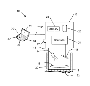
Fig. 1A is a schematic drawing of a system for noninvasive analysis of
subcutaneous
liquids based on reflection of infrared radiation, in accordance with an
embodiment of the
present invention.
Liquid analysis system 10 includes reflection measurement unit 12. Reflection
measurement unit 12 includes infrared radiation source 14 and radiation
detector 16. Unit
aperture 19 on optical head 13 of reflection measurement unit 12 is configured
to be
placed on or near a tissue surface 22 of a patient so as to measure infrared
radiation that is
reflected from tissue that is covered by tissue surface 22. Liquid analysis
system 10 is
configured to determine the state of subcutaneous tissue, such as the presence
of absence
of a subcutaneous medical condition in tissue that is covered by tissue
surface 22, or to
measure the presence or absence of an administered substance in blood that
flows via the
tissue.
Reflection measurement unit 12 may be configured to be held and manipulated by
a single
hand of a user. For example, the user may include a healthcare professional, a
caregiver, or
the patient. Reflection measurement unit 12 may include an internal power
source in the
form of a battery or other self-contained power source, or may be connectable
to an
external power source. Reflection measurement unit 12, optical head 13, or
both may have
a generally or substantially cylindrical form, or may have another geometrical
form or
shape. Unit aperture 19 may thus have a substantially round or elliptic shape,
or another
shape.
11
Date Recue/Date Received 2020-10-07
Unit aperture 19 of optical head 13 may include one or more component
apertures.
Fig. 1B is a schematic illustration of a plurality of component apertures of
an optical head
of the system shown in Fig. 1A. Unit aperture 19 includes a plurality of
component
apertures 40. Each component apertures 40 may be configured to enable passage
of
radiation from a single component infrared source of infrared radiation source
14 or to a
component detector of radiation (e.g., infrared) detector 16. In the
configuration shown,
unit aperture 19 is round and component apertures 40 are arranged in a
hexagonal pattern.
Other configurations may include other shapes of unit aperture 19 or other
arrangements
of component apertures 40.
Infrared radiation source 14 is configured to irradiate tissue surface 22 with
SWIR
radiation via unit aperture 19 of optical head 13. Infrared radiation source
14 may include
one or more separate component infrared sources. For example, two or more
component
infrared sources may each produce SWIR radiation in one or more spectral
bands. For
example, infrared radiation source 14 may include tungsten-halogen or other
incandescent
lamp, a xenon lamp or other gas emission radiation source, a fluorescent
radiation source,
an electronic radiation source (e.g., light emitting diode, laser diode, or
laser), or other
radiation source.
Infrared radiation source 14 may include a single wideband infrared source
that emits
radiation over two or more spectral bands. In some cases, infrared radiation
from a single
wideband infrared source may be separately channeled via separate spectral
band selection
devices (e.g., that include filters, prisms, or gratings) to form effective
single-band
sources. For example, the separate channeling may be performed sequentially to
radiate
infrared radiation in different spectral bands in quick succession (e.g., less
than a
millisecond) via a single component aperture 40 of unit aperture 19. As
another example,
the radiation from the wideband source may be divided (e.g., using a beam
splitter) and
concurrently channeled via different band-selection devices to concurrently
radiate in
different spectral bands via separate component apertures 40 of unit aperture
19.
Optics 18 of optical head 13 may direct infrared radiation from infrared
radiation source
14 out unit aperture 19 (or from a component infrared source of infrared
radiation source
14 out a component aperture 40 of unit aperture 19) to tissue surface 22. For
example,
optics 18 may include one or more mirrors, reflectors, light pipes or optical
fibers, lenses,
12
Date Recue/Date Received 2020-10-07
filters, gratings, polarizers, beam splitters, prisms, apertures, collimators,
shutters, or other
components. Similarly, optics 18 may direct radiation from tissue surface 22
(e.g.,
reflected radiation) via unit aperture 19 to infrared radiation detector 16
(or via a
component aperture 40 of unit aperture 19 to a component detector of infrared
radiation
detector 16). One or more components of optics 18 may function both to direct
radiation
from infrared radiation source 14 to tissue surface 22, and to direct
radiation from tissue
surface 22 to infrared radiation detector 16. Alternatively or in addition,
separate
components of optics 18 may be provided for either directing radiation from
infrared
radiation source 14 to tissue surface 22 or for directing radiation from
tissue surface 22 to
infrared detector 16.
Optics 18 may be or may include a dispersive element (e.g., grating, prism,
element with
spectrally selective optical layers or coating, or another dispersive
element), and a micro-
mirror array for directing radiation of one or more selected wavelengths
toward unit
aperture 19 (e.g., for limiting irradiation of tissue surface 22 to selected
wavelengths), or
toward infrared detector 16 (e.g., for limiting detection of reflected or
transmitted radiation
to selected wavelengths).
Optics 18 may be configured to direct a portion of radiation that is emitted
by infrared
radiation source 14 to infrared detector 16. Thus, an intensity of the
radiation that is
emitted by infrared radiation source 14 may be monitored. Optics 18 may
include a shutter
or other component that is configured to block radiation (e.g., that is
emitted by infrared
radiation source 14) from reaching infrared detector 16. When the radiation is
blocked, a
baseline measurement may be made (e.g., a dark current or a detection level
that is due to
stray radiation).
Infrared detector 16 may be configured to detect SWIR radiation from tissue
surface 22
that enters reflection measurement unit 12 via unit aperture 19. Infrared
detector 16 may
include one or more component detectors. For example, radiation that is
reflected by tissue
surface 22 may be enabled to impinge on a component detector of infrared
detector 16 via
one of component apertures 40.
Two or more different component radiation detectors may be configured to
detect, or be
optimized to detect, SWIR radiation in one or more spectral bands. A component
detector
may include a solid state or other photoelectric transducer or photodetector
that is
13
Date Recue/Date Received 2020-10-07
configured or optimized for one or more spectral bands of SWIR radiation. A
component
detector may include a thermal detector, a photon detector (e.g., including
InGaAS), or
another type of wideband detector. The temperature of a component detect of
infrared
detector 16 may be regulated (e.g., via thermoelectric cooling or heating) or
may be
unregulated.
Infrared detector 16 or controller 28 may include an amplifier to amplify a
detection signal
that is produced by infrared detector 16. For example, the amplifier may
include a trans-
impedance amplifier or other amplifier.
Infrared detector 16 or controller 28 may include a logarithmic converter that
enables
direct calculation of an absorbance value of the tissue, or of a quantity that
is proportional
to an absorbance. The absorbance data may be used to analyze a liquid, such as
water or
blood, below tissue surface 22 (e.g., detect a pressure ulcer or a
concentration of a drug or
other substance in the blood).
Component apertures 40 may be arranged such that radiation in a particular
wavelength
band that is emitted by a particular component infrared source of infrared
radiation source
14 and that is reflected by tissue surface 22 is likely to impinge on a
corresponding (e.g.,
configured or optimized to detect radiation in that same wavelength band)
component
detector of infrared detector 16. For example, the positions of a pair of
corresponding
component apertures 40 may be arranged such that radiation that irradiates
tissue surface
22 via one of the corresponding component apertures 40 may be specularly
reflected by
tissue surface 22 into the other of the pair of corresponding component
apertures 40.
Unit aperture 19 of optical head 13 may be configured to be placed against or
near tissue
surface 22. Optical head 13 may be provided with a removable protective cover
20 that
may be placed over unit aperture 19 when reflection measurement unit 12 is in
use. At
least an outer surface of removable protective cover 20 may be constructed of
materials
that are suitable (e.g., approved by an appropriate organization) for contact
with human
skin or other tissue surfaces. At least a region of protective cover 20 (e.g.,
a region that is
configured for placement over unit aperture 19) is substantially transparent
or translucent
in the spectral bands in which reflection measurement unit 12 is configured to
operate.
Suitable materials may include, for example, rigid vinyl, polycarbonate, POLY
IRO
14
Date Recue/Date Received 2020-10-07
plastic materials, or other materials such as poly urethane (PU)b,
thermoplastic elastomers
(TPE), silicones (LSR) and the like.
Removable protective cover 20 may include a structure (e.g., tab, projection,
notch, clip,
or other structure) that cooperates with corresponding structure on optical
head 13 to
prevent or inhibit removable protective cover 20 from accidentally or
unintentionally
falling off of optical head 13, e.g., during use.
Protective cover 20 may be disposable, cleanable, or sterilizable. Removable
protective
cover 20 may be removed from optical head 13 and replaced (e.g., with a
different
removable protective cover 20, or with the same removable protective cover 20
after
cleaning and sterilization) between uses of reflection measurement unit 12 on
different
patients. Use of removable protective cover 20 may enable sanitary use of
reflection
measurement unit 12 on different patients while not exposing reflection
measurement unit
12 from repeated cleaning or sterilization.
Liquid analysis system 10 may include a controller 28. Controller 28 may
include a
microcontroller unit (MCU), or one or more other types of controller,
microprocessor or
processor. Controller 28 may include for example two or more
intercommunicating
devices or units. Controller 28 may be configured to control operation of
infrared radiation
source 14, and to receive signals that are indicative of detected radiation
from infrared
detector 16. For example, controller 28 may include circuitry that is
configured to control
.. operation of infrared radiation source 14 and infrared detector 16.
Controller 28 may be
configured to operate in response to operation of user controls 27. For
example, user
controls 27 may include one or more user touch-operable controls, such as
pushbuttons,
dials, switches, levers, touch-sensitive surfaces, or other touch-operable
controls. User
controls 27 may include other types of controls, such as light-sensitive
controls, sound-
operated controls, electromagnetically-operable controls, proximity sensors,
pressure
sensors, or other types of controls.
Controller 28 may be configured to dynamically adjust the intensity of
radiation that is
emitted by infrared radiation source 14, e.g., in accordance with intensities
that are
detected by infrared detector 16. For example, the intensity may be adjusted
to
accommodate various tissue thicknesses, skin coloration, or other
characteristics. The
Date Recue/Date Received 2020-10-07
intensities of a component infrared source may be adjusted in accordance with
output of
another component infrared source.
Controller 28 may be configured to digitally filter the signals of infrared
detector 16, e.g.,
to remove effects of baseline wandering and artifacts caused by patient
movement.
Controller 28 may include a processor or processing units that may be
configured to
operate in accordance with programmed instructions. Controller 28 or a
processor of
controller 28 may communicate with an external device 30 via connection 36.
External
processing device 30 may represent a device with processing capability, such
as a
computer, smartphone, or other device. External processing device 30 may be
portable
(e.g., a portable computer or smartphone) or may be fixed (e.g., a server).
External
processing device 30 may include or communicate with an input device 34 (e.g.,
keyboard,
keypad, touch screen, pointing device, or other input device), an output
device 32 (e.g.,
display screen or other output device), or both. Connection 36 may represent a
wire or
cable connection, a wireless connection (e.g., Bluetooth), a network
connection, or another
communications connection.
External processing device 30 may be utilized to communicate commands or
programmed
instructions to control operation of controller 28. For example, external
processing device
30 may be operated using input device 34 to download parameters or
instructions (e.g., a
measurement protocol) to controller 28. Measured results from operation of
reflection
measurement unit 12, or results of analysis of the measured results, preformed
by, for
example, external processing device's processor 38, may be output by output
device 32 of
external processing device 30 for examination or review by a user of liquid
analysis
system 10.
External processing device 30 may communicate (e.g., via a network such as the
Internet)
with one or more other processors, computers, or servers. For example, measure
spectral
reflection or transmission data may be communicated to a remote server. The
remote
server may analyzed the transmitted data and return a diagnosis or other
indication of a
state of a medical condition.
Controller 28 may communicate with memory 24 (and/or external processing
device's
memory 39). Memory 24 may include one or more volatile or nonvolatile memory
devices. Memory 24 may be incorporated within reflection measurement unit 12,
external
16
Date Recue/Date Received 2020-10-07
processing device 30, or elsewhere. Memory 24 may be utilized to store, for
example,
programmed instructions for operation of controller 28, data or parameters for
use by
controller 28 during operation, or results of operation of controller 28.
Controller 28 and or processor 38 may communicate with data storage device 26.
Data
storage device 26 may include one or more fixed or removable nonvolatile data
storage
devices. Data storage device 26 may be incorporated within reflection
measurement unit
12, external processing device 30, or elsewhere. For example, data storage
device 26 may
include a computer readable medium for storing program instructions for
operation of
processing unit of controller 28 or of external processing device 30. It is
noted that data
storage device 26 may be remote from the processing unit. In such cases data
storage
device 26 may be a storage device of a remote server storing an installation
package or
packages that can be downloaded and installed for execution by the processing
unit. Data
storage device 26 may be utilized to store data or parameters for use by
controller 28
during operation or results of operation of controller 28 (e.g., detection of
radiation).
Data storage device 26 may be used to store data that relates spectral
absorption,
transmission, or reflection characteristics of tissue surface 22 to one or
more medical
conditions. The data may be stored in the form of a database. Processor or
controller 28,
or another processor or controller may be configured to carry out methods as
described
herein.
In accordance with an embodiment of the present invention, a system for
noninvasive
analysis of subcutaneous liquids may be based on measured transmission of SWIR
radiation.
Fig. 2A is a schematic drawing of a measurement unit of a system for
noninvasive analysis
of subcutaneous liquids based on transmission of infrared radiation, in
accordance with an
.. embodiment of the present invention.
Transmission measurement unit 50 may be used in a system for noninvasive
analysis of
subcutaneous liquids, such as in liquid analysis system 10 (e.g., in place of,
or in addition
to, reflection measurement unit 12 of Fig. 1A). Transmission measurement unit
50 is
configured to measure transmission through a body part 52. For example, body
part 52
may represent a part of the body (e.g., ear, finger, fold of skin) through
which a
measurable fraction of SWIR radiation is transmitted.
17
Date Recue/Date Received 2020-10-07
Transmission measurement unit 50 includes radiation source arm 54 and
detection arm 55.
Radiation source arm 54 may include infrared radiation source 14 and source
optics 53a.
In some cases, infrared radiation source 14 may be located outside of
radiation source arm
54. In such a case, source optics 53a may be configured (e.g., with a mirror,
light pipe, or
optical fiber) to convey radiation from infrared radiation source 14 to source
arm aperture
57a.
As described above, infrared radiation source 14 may include two or more
separate
component infrared sources. Source optics 53a may be configured to convey
radiation
from the component infrared sources, concurrently or sequentially, to source
arm aperture
57a, or to separate component apertures of source arm aperture 57a.
Source optics 53a may be or may include a dispersive element (e.g., grating,
prism,
element with spectrally selective optical layers or coating, or another
dispersive element),
focusing optics, and a micro-mirror array for directing radiation of one or
more selected
wavelengths of radiation from infrared radiation source 14 toward source arm
aperture
57a.
Detection arm 55 may include infrared detector 16 and detector optics 53b. In
some cases,
infrared detector 16 may be located outside of detection arm 55. In such a
case, detector
optics 53b may be configured (e.g., with a mirror, light pipe, or optical
fiber) to convey
radiation from detection arm aperture 57b to infrared detector 16.
As described above, infrared detector 16 may include two or more separate
component
detectors. Detector optics 53b may be configured to convey radiation from
detection arm
aperture 57b, concurrently or sequentially, to component detectors of infrared
detector 16,
or from separate component apertures of detection arm aperture 57b to
component
detectors of infrared radiation detector 16.
Detector optics 53b may include a dispersive element (e.g., grating, prism,
element with
spectrally selective optical layers or coating, or another dispersive
element), focusing
optics, and a micro-mirror array for directing radiation of one or more
selected
wavelengths of radiation from detector arm aperture 57b toward infrared
detector 16.
18
Date Recue/Date Received 2020-10-07
Radiation source arm 54, detection arm 55, or both, may be rotated outward
(away from
one another) or inward (toward one another). Outward rotation of radiation
source arm 54
or detection arm 55 may enable insertion of body part 52 between the arms.
Inward
rotation of radiation source arm 54 or detection arm 55 may bring source arm
aperture 57a
and detection arm aperture 57b into contact with or near to body part 52.
Source arm
aperture 57a and detection arm aperture 57b may each be covered with a
removable
protective cover 20.
A rotation mechanism 56 may be configured to enable the outward or inward
rotation of
radiation source arm 54 and detection arm 55. For example, rotation mechanism
56 may
include a hinge, gimbal, bearing, or other mechanism to enable rotation of
radiation source
arm 54 or detection arm 55. For example, a separate rotation mechanism 56 for
one of
radiation source arm 54 and detection arm 55. Separate rotation mechanisms 56
may be
provided for both radiation source arm 54 and detection arm 55 (e.g., as shown
schematically in Fig. 2A). A single rotation mechanism 56 may be provided
(e.g., a single
hinge mechanism) between radiation source arm 54 and detection arm 55 (e.g.,
as shown
schematically in Figs. 2B and 2C). Rotation mechanism 56 may include a spring,
latch, or
other mechanism to hold radiation source arm 54 and detection arm 55 against
body part
52 when body part 52 is inserted between radiation source arm 54 and detection
arm 55.
Thus, rotation mechanism 56 may attach transmission measurement unit 50 to
body part
52.
Rotation mechanism 56 may be configured to enable measurement of a thickness
of body
part 52. For example, rotation mechanism may include an encoder or other
measuring
device for measuring an angle of rotation of rotation mechanism 56.
Alternatively or in
addition, rotation mechanism may include an angular scale or mechanical
rotation gauge
for determining an angle of rotation of rotation mechanism 56. A measured
rotation angle,
together with a known distance from (e.g., and axis of rotation of) rotation
mechanism 56
from source arm aperture 57a or from detection arm aperture 57b may be used
(e.g., by a
processor or controller) to calculate the thickness.
When source arm aperture 57a and detection arm aperture 57b are positioned on
or near
body part 52, transmission measurement unit 50 may be operated to measure of
transmission of SWIR radiation from infrared radiation source 14 through body
part 52 to
infrared detector 16.
19
Date Recue/Date Received 2020-10-07
Fig. 2B schematically illustrates attachment of the measurement unit of Fig.
2A to a
finger.
For example, transmission measurement unit 50 may be clipped to finger tip 60
to measure
transmission of SWIR radiation through finger tip 60. For example, the
transmission
measurement may be indicative of a medical condition, such as the
concentration of a
substance in blood that flows through finger tip 60.
Fig. 2C schematically illustrates attachment of the measurement unit of Fig.
2A to an ear.
For example, transmission measurement unit 50 may be clipped to outer ear 62
to measure
transmission of SWIR radiation through outer ear 62. For example, the
transmission
measurement may be indicative of a medical condition, such as the
concentration of a
substance in blood that flows through outer ear 62.
In accordance with an embodiment of the present invention, a reflection or
transmission
measurement may be utilized to characterize tissue in a patient.
A spectral reflectance measurement R(.1) may be expressed as
R(2)= I(A)¨ Bo (2)
4(2) ¨ Bo (A)
where AN is a measured source intensity, /(.1) is a measured reflected
intensity, and B0(i1)
is a baseline measurement (e.g., measured when infrared radiation source 14 is
turned off
or when infrared detector 16 is covered, e.g., by a shutter). Source intensity
10(.1) may be
monitored continuously (e.g., by a dedicated detector), or may be measured in
the absence
of tissue (e.g., a skin surface or body part) in the optical path from
infrared radiation
source 14 to infrared detector 16.
In some cases, baseline measurement B0(2) may be ignored when B0(1) is much
smaller
than /001) or /01).
The relative spectral absorbance AO, which may be used to characterize the
tissue, may
be calculated by:
R(
A(2)= ¨log2) ¨ log /(2)
_ a R _ aRI0(2) _1,10 Bo
Date Recue/Date Received 2020-10-07
where the dimensionless value A(/1) = aAL is the relative spectral absorbance,
aA is the
absorption coefficient, L is the path-length or tissue penetration depth; and
ocR is the
reflection coefficient. In general, the relative absorbance A(A) corresponds
to spectral
extinction, which results from both absorption and scattering.
Reflectance measurements in two or more spectral bands, AA, may be performed
on a
single region of skin or tissue to yield separate measured values of A(z1) or
ROM. For
example, the spectral bands may include two or more of the wavelength ranges
¨1400 nm
¨ 1500 nm (strongly absorbed by water), ¨1000 nm ¨ 1350 nm (no strong
absorption by
water), and ¨1500 nm¨ 2100 nm (no strong absorption by water).
The differential absorption AD zif may be calculated from measurements in two
wavelength
bands, AA, and AA], where i
ADiff = (A21)¨ log[R(A2, )]¨ log[ARõf )]¨ log
Rõf (AA, )_
Aref and Rref refer the absorbance and reflectance in one of the spectral
bands that serves as
a reference band. For example, radiation in the reference band may be largely
absorbed,
scattered, or transmitted whether or not a medical condition to be detected is
present. For
example, the wavelength range of ¨1400 nm ¨ 1500 nm (strong water absorption),
a
portion of this range, or another similarly unaffected spectral range may be
selected as the
reference band.
Absorption, scattering, or transmission of radiation in one of the other
spectral bands,
referred to as the operating band, may be detectibly dependent on the presence
of absence
of the medical condition. For example, the operating band may include one or
both of the
spectral ranges ¨1000 nm ¨ 1350 nm, ¨1550 nm ¨ 2100 nm, one or more portions
of one
or both spectral ranges, or another suitable spectral range. Here, and
throughout the
specification, the symbol ¨ indicates an approximation (e.g., 10%).
The differential absorption may be related to the state of the tissue (e.g.,
presence,
absence, degree, or other state of a medical condition). For example, a
database of
previous measurement results may associate a value of a differential
absorption with a
state of a medical condition such as inflammation (e.g., otitis media, or
other
inflammation), tumor (e.g., in the colon, or elsewhere), or other conditions.
The
differential absorption value may be used to differentiate between conditions
(e.g.,
21
Date Recue/Date Received 2020-10-07
inflammation and tumor, healthy and diseased tissue), detect or measure liquid
within
tissue, or other conditions.
In some cases, reflection measurements may be made on a region of a tissue
surface when
the underlying tissue is expected to be healthy (e.g., based on other medical
indications),
and another where presence of unhealthy tissue is suspected.
The differential absorption AD zif of two measurements with the same setup and
in the same
wave-band AAb i = 1,2,3 yield two different spectral absorbance values,
Aõj(Ak) and
Asus(A)L), which correspond to healthy tissue (reference absorbance, Ara) and
suspicious
tissue A sus respectively:
ADIff = A SUS (A111) Aõf (AA) log[R sus (A 2,)]¨ log [R (AA)j
lo R (A2 ,)
g
sus
¨
_Rref (A21) _
To improve detectability, all three spectral ranges A)\,i i = 1,2,3 can be
used
simultaneously.
In some cases, chromophore content may be measured quantitatively. In some
cases,
.. differentiation is limited to two states, e.g., healthy or diseased (e.g.,
presence of pressure
ulcer indicated by accumulation of subcutaneous liquid in the) tissue.
In some cases, a state of a medical condition (e.g., presence of diseased
tissue) may be
determined by calculating the tissue liquid index (TLI), the sub-dermal fluid
index (SDFI),
or another quantity. A parameter C, such as TLI, SDFI, or another parameter,
can be
defined as a normalized difference of the reflectance as measured at two
different
wavelength bands AA, and AAJ, where i
=
R(A21)¨ R(A2 j)
C õ \
R(A2,)+ ROA )
In some cases, C may be approximated by
R(A2,)¨ R(A2 j)
C= _____________________________ or
R(A21)
R(A2,)
C = õ __________ \ r
R(A2)+R(A21)
) + ROA )
22
Date Recue/Date Received 2020-10-07
C = slope[R(A),)]
Fig. 3 shows an example of a graph of spectral reflectance.
Graph 70 shows measured reflectance in arbitrary units as a function of
wavelength.
Normal tissue curve 72 may represent spectral reflectance for normal, or
healthy, tissue.
Diseased tissue curve 74 may represent spectral reflectance for diseased, or
unhealthy,
tissue. Water curve 76 represents spectral transmittance for water (e.g., for
a particular
optical path such as 1 mm; transmittance = 1 ¨ absorbance) in arbitrary units.
It may be noted that in the wavelength band of 1400 nm ¨ 1500 nm (low water
reflectance
due to strong absorption of radiation), there is little difference between
normal tissue curve
72 and diseased tissue curve 74. However, in the adjacent bands (e.g.,
wavelength less
than about 1350 nm), the difference is more pronounced.
Quantification of chromophores may enable estimation of changes in
concentration levels
of substances or materials (e.g., drugs, or other substances) that may be
administrated by
injection, infusion, or otherwise.
The spectral transmittance of blood TB may be expressed as
TB(2)= I(2)110(2)=+a(2)).L
where aB(.1) represents the absorption coefficient of blood and (e.g., in
units of cm'),
respectively, at wavelength /1, oc(k) is the absorption coefficient of
additional components
of the tissue, and L is the length of the absorbing path (e.g., in cm). /(.1)
is the detected
intensity of transmitted radiation, and /0W is the intensity of incident
radiation.
Similarly, T%s, the spectral transmittance of a mixture of blood and an
introduced
substance may be expressed as
To% s (2)= /(2)//o (2) e s
L
where as(k) represents the absorption coefficient of the introduced substance.
The absorption coefficients may relate to the concentrations of blood CB and
of the
introduced substance Cs:
aB(/1)= EB(A) = CB, and
as(k) = Es(2) =Cs.
23
Date Recue/Date Received 2020-10-07
where EB and Es represent the absorptivity coefficients of blood and of the
introduced
substance (e.g., in units of 1-mo1-1 -cm-1 or 1g' cm'; also referred to as the
specific
absorption coefficient or mass absorption coefficient), respectively.
The relative absorbance As (dimensionless) at wavelength A may be related to
the
concentration of introduced substance:
T
As(2,C s)= log = (Es (2)= Cs + a(2))= L
B
The relative absorbance may be expressed as a linear equation:
As Pi = Cs +p2
with coefficient pi (e.g. in 1-g1) andp2 (dimensionless).
The normalized spectral transmittance S at a wavelength kn may be calculated
from a
measurement k as:
measn
/ ,k) 'dark (An )
s(An k) =
I ref (An >k 0) dark (11' n)
Imeas(11n, k) is a measured radiation intensity at wavelength kn for
measurement k, /m ()
easv-n,
k) being proportional to T%s. /rej()n, ko) is a reference signal for a
measurement ko made
prior to introduction of the substance into the blood, /rej()n, ko) being
proportional to TB-
-Ida/4/10 represents a baseline measurement that is made in the absence of a
radiation
source, e.g., when the radiation source is switched off.
The differential spectral absorbance AD zif for measurement k at two
wavelengths A/ and 22
may thus be calculated as
Apo, (Ai, 22) = A(21)¨ A(22) = log[S(,k)]-1og[S(A2,k)] = log,
S(22,k)
For example, TB and Twos may represent relative spectral transmittances of
blood and of a
mixture of blood and a introduced substance measured at two wavelengths A/ and
A2:
(111)
77(11,\ = e
2 )
24
Date Recue/Date Received 2020-10-07
T%S =T(21)
\= e¨(Ks +KB +a }L
T(22)
Kg = (aB(A2) ¨ aB(A1)) and Ks = (as(A2) ¨ as(A1)) represent the differential
absorption
coefficients of blood and of the introduced substance, respectively.
The relative differential absorbance As (dimensionless) at two wavelengths 2/
and 22 is
related to the concentration of introduced substance as:
(
As(A, 22, Cs ) = log = ((ss k ¨ Es (22)). Cs + a(2)). L
B
The normalized spectral transmittance S at two wavelengths ki and 2\,2 may be
calculated
from measurement k as:
Sk,22,k)¨ [meas (21,k)- Idark(21)11[1 meas(22,k) dark(22)1
['ref (21,k 0) I dark(21)11[1 ref (22 >k 0) hark (22)]
The differential spectral absorbance AD zif for measurement k at two
wavelengths 2/ and 22,
then is:
ADiff (111 22 = log[Sk,2,0]
The differential spectral absorbance measurement may eliminate the effects of
background
materials. For example, if the absorption and scattering by the background
materials (e.g.,
tissue components other than water, or a substance that is introduced into the
blood) are
substantially constant in both measured spectral bands, than the differential
spectral
absorbance may be indicative of the water content of the tissue (e.g., as
indicative of the
presence or absence of a medical condition in which fluids accumulate in the
tissue, or
indicative of water content of blood).
A known relationship between the differential spectral absorbance and a
concentration of
the substance in the blood may be applied to the measured differential
spectral absorbance
to determine a concentration of the substance in the blood. For example, the
known
relationship be applied as a parameterized formula expressing the relationship
(e.g., a
polynomial or other formula), as a lookup table, or in another manner.
Fig. 4 shows a graph of an example of a relationship of absorbance to
concentration of a
substance.
Date Recue/Date Received 2020-10-07
Line 82 of graph 80 shows a relationship between a relative absorbance
(dimensionless)
and the concentration of a substance (e.g., propofol) in blood, as plotted on
a logarithmic
scale (e.g., in units of g/m1). The relationship may be derived from
laboratory
measurements 84, e.g., from transmission measurements on cuvettes containing
various
concentrations of the substance in blood. A relationship may be derived by
application of a
fitting technique to fit line 82 to laboratory measurements 84.
Fig. 5 is a flowchart depicting a method for noninvasive analysis of
subcutaneous liquids,
in accordance with an embodiment of the present invention.
It should be understood with respect to any flowchart referenced herein that
the division of
the illustrated method into discrete operations represented by blocks of the
flowchart has
been selected for convenience and clarity only. Alternative division of the
illustrated
method into discrete operations is possible with equivalent results. Such
alternative
division of the illustrated method into discrete operations should be
understood as
representing other embodiments of the illustrated method.
Similarly, it should be understood that, unless indicated otherwise, the
illustrated order of
execution of the operations represented by blocks of any flowchart referenced
herein has
been selected for convenience and clarity only. Operations of the illustrated
method may
be executed in an alternative order, or concurrently, with equivalent results.
Such
reordering of operations of the illustrated method should be understood as
representing
other embodiments of the illustrated method.
Operations of subcutaneous liquid analysis method 100 may be executed by a
processor of
a controller of a device for subcutaneous liquid analysis, or by a processor
that is in
communication with a controller of a device for subcutaneous liquid analysis.
Execution of subcutaneous liquid analysis method 100 may be initiated by a
user of a
device for subcutaneous liquid analysis. For example, a user may operate a
control to
initiate execution of subcutaneous liquid analysis method 100. As another
example,
execution of subcutaneous liquid analysis method 100 may be initiated
automatically
when a device for subcutaneous liquid analysis is activated (e.g., turned on),
and when it is
detected (e.g., by an optical sensor or by a proximity sensor) that one or
more apertures of
the device are in contact with a tissue surface.
26
Date Recue/Date Received 2020-10-07
The tissue may be irradiated with SWIR radiation in a spectral band that is
strongly
absorbed by water (block 110). For example, a tissue surface may be irradiated
with SWIR
radiation in the wavelength range from about 1400 nm to about 1500 nm. The
radiation
may originate from a wideband source (e.g., an incandescent or other thermal
source, or
from a fluorescent source), or from a narrowband source (e.g., laser diode or
light emitting
diode). The irradiation may be filtered or otherwise manipulated. For example,
radiation
that is emitted by a wideband radiation source may be filtered or otherwise
manipulated to
select only that radiation that is within the water-absorbed spectral band.
The tissue may be irradiated with SWIR radiation in a spectral band that is
adjacent to the
water-absorbed spectral band (block 120). For example, a gap between the
adjacent
spectral band and the water-absorbed spectral band may be no more than 200 nm.
In some
cases, the gap may be no more than 100 nm. A single wideband source may
produce both
the radiation in the water-absorbed spectral band and in the adjacent spectral
band. In
some cases, the radiation in the adjacent spectral band may be isolated from
radiation that
is emitted by a wideband source prior to irradiation of the tissue.
Radiation that emerges from the tissue in each of the spectral bands may be
detected
(block 130). The detector is configured to produce a signal that is indicative
of an intensity
of the emerging radiation.
For example, one or more detectors may be configured to detect radiation that
emerges
from the tissue surface that is irradiated. For example, optics of the
radiation source and
the radiation detector may be aimed at a single tissue surface. In this case,
the detector is
configured to measure backscattered or reflected radiation. As another
example, the
detector may be configured to detect radiation that emerges from a tissue
surface on the
opposite side of the tissue from the tissue surface that is irradiated. In
this case, the
detector is configured to measure radiation that is transmitted by the tissue.
In some cases, different detectors may be configured to measure emerging
radiation in
each of the wavelength bands. For example, each detector may be constructed of
a
material that produces an electric signal only when irradiated with radiation
in one of the
spectral bands. As another example, detector optics (e.g., including a filter
or grating) may
restrict radiation that is outside of that spectral band from irradiating the
detector. In some
cases, the detector may be configured to detect radiation in both spectral
bands. In this
27
Date Recue/Date Received 2020-10-07
case, separate measurement of the emerging radiation in the different spectral
bands may
be effected by separate (e.g., sequential or alternating) irradiation of the
tissue with
radiation in each of the spectral bands.
In some embodiments, emerging radiation may be measured at different distances
from a
location of the irradiation. For example, emerging radiation may be measured
concurrently
by a plurality of detectors that are arranged at different distances from a
location on the
tissue surface that is irradiated. As another example, emerging radiation may
be measured
sequentially in time at different distances by one or more detectors whose
distance from
the location of irradiation may be changed (e.g., automatically or manually).
In this case, a
detector may be provided with a sensor or mechanism (e.g., encoder or other
sensor or
mechanism) that is configured to measure a distance between a detector and the
radiation
source. In some embodiments, signals received from each detector may
correspond to the
distance of the detector from the light source. In some embodiments, the shape
and/or
intensity of a signal received by a detector may correspond to a medical
condition in the
tissue, for example shape of a signal changed in measurements for healthy
tissue and for
deep tissue injury, so that the shape of the signal received for a healthy
tissue changes
when measuring an injured tissue of the same subject (e.g., person). The shape
of a signal
may change because of different types of chromophores and different types of
chemical
functional groups on a chromophore. For example a phenol ring on a chromophore
will
have different absorption graph shape in comparison to a CO chemical bond, CH
chemical bond, or CN chemical bond. Absorption graph different shape means
different
location of the absorption peak or peaks in different wavelengths and at
different peak
heights (amplitudes). In some embodiments, a plurality of detectors may be
used, each of
the plurality of detectors may have a different distance from the radiation
source. It should
be appreciated that the signal received by each detector may have different
amplitudes.
According to some embodiments, the processor or controller may combine the
readings of
the plurality of detectors and calculate the slope of the combined absorption
graph (e.g., a
graph that represents the result of combining all detected amplitudes). A
change in the
state of the tissue may be determined, according to some embodiments, when a
change in
the slope of the combined absorption graph is detected (e.g., by processor 38
and/or
controller 28 in Fig. 1).
28
Date Recue/Date Received 2020-10-07
Detection of the emerging radiation may be preceded by, followed by, or may be
concurrent with one or more calibration, baseline, or reference measurements.
For
example, a baseline or dark measurement may be made when the radiation source
is not
being operated. The baseline measurement may determine a signal that is
produced by the
detector (e.g., due to detector electronics or to stray radiation impinging on
the detector
surface) when no radiation of interest is present. A calibration measurement
may be made
when radiation that is emitted by the source is directly (e.g., not via
tissue) conveyed to the
detector. Such a calibration measurement, when made concurrently with, or
immediately
prior to or after, the measurement of emerging radiation may enable
compensation for
drifting in source intensity or detector sensibility. In some cases, a
reference measurement
may be made on the radiation that emerges from the tissue under known
conditions (e.g.,
on a skin surface that is known to overlie healthy tissue, or prior to
introduction of a
substance into the blood).
The measurements of emerging radiation may be used to calculate a relative
absorption by
the tissue (block 140).
For example, a relative reflectance may be calculated by calculating a ratio
of a measured
intensity of reflected (e.g., due to backscattering) radiation in one of the
spectral bands to
the measured intensity of reflected radiation in another spectral band. A
relative absorption
may be inferred from the relative reflectance, e.g., on the assumption that a
characteristic
penetration depth of the radiation is the same in both spectral bands. If the
characteristic
penetration depth of the radiation is known (e.g., from laboratory
experiments), a
differential absorbance may be calculated.
A relative transmission may be calculated by calculating a ratio of a measured
intensity of
transmitted radiation in one of the spectral bands to the measured intensity
of transmitted
radiation in another spectral band. Since the path length through the tissue
is the same for
both spectral bands, a relative absorption may be inferred from the relative
transmission. If
the thickness of the tissue (L) is known (or may be estimated) and constant, a
differential
absorbance of the tissue may be calculated.
The relative differential absorbance As (dimensionless) at two wavelengths 2/
and 22 is
related to the concentration of introduced substance as:
29
Date Recue/Date Received 2020-10-07
( T
As(ili, 22 ,C s) = log a(2))*
7'
B
According to some embodiments, Raman spectroscopy as described in further
detail
below, may be employed to analyze the measurement data, and determine changes
in
concentration of any chemical compound inside the tissue due to, for example,
a deep
tissue injury. The calculated relative absorption may be utilized to determine
a state of the
tissue (block 150). For example, a calculated differential absorbance,
relative reflection,
relative transmission, or other calculated value that is related to relative
absorption may be
compared to previously measured values. The previously measured values may
relate to a
particular body part, suspected medical condition, introduced substance, or
may otherwise
relate to a specific state that is being examined. The comparison may include
substitution
of the calculated value in a functional relationship, may be used to retrieve
an indication of
the state of the tissue from a lookup table, or may be otherwise utilized in
determining a
state of the tissue.
It should be noted that deep tissue injuries may include presence of liquids
at depths larger
than about 5mm compared to a corresponding region of a healthy tissue (e.g.,
of a healthy
patient). Furthermore, deep tissue injuries may include increasing
concentration (over
time) of substances that are products of ischemic processes (causing damage to
the tissue)
such as free fatty acids and/or glycerol which are the breakdown products of
the fatty part
of the tissue (triglyceride).. In the blood stream (unlike other tissues)
triglyceride may
.. appear in the form of very low density lipoproteins (VLDL) while in other
tissue the
structure of triglyceride is maintained. Accumulation of other substances
(e.g., protease or
myoglobin) may also indicate presence of a deep tissue injury. Therefore, in
order to
determine a state of deep tissue injury, calibration may be initially
performed to identify
substances in tissue indicating such an injury. Using the calculated relative
absorption a
state of deep tissue injury may be therefore determined, as described above.
According to some embodiments, a reflectance measurement may include detecting
reflected radiation at different lateral distances from a radiation source. In
some
embodiments, analysis of such reflectance measurements at different distances
may
indicate a depth within the tissue of a detected feature.
Fig. 6A schematically illustrates a system for measurement of reflection at a
distance from
a radiation source, in accordance with an embodiment of the present invention.
Date Recue/Date Received 2020-10-07
According to some embodiments, reflection measurement system 200 may include a
source unit 202 and one or more detection units 204. Source unit 202 may
include at least
one infrared (IR) radiation source 14 and source optics 18a (e.g., lenses
etc.) for directing
a beam of radiation, e.g., into a tissue surface 22. Each detector unit 204
may include at
least one IR detector 16 and detector optics 18b (e.g., lenses etc.) for
directing radiation,
for instance radiation emerging from tissue surface 22, toward infrared
detector 16.
Detector unit 204 may be located at a measurement distance 206 from source
unit 202. For
example, measurement distance 206 may correspond to a distance between a
center of an
aperture of source unit 202 to a center of detector unit 204, and/or another
measurement
that characterizes a lateral distance between source unit 202 and detector
unit 204.
In some embodiments, at least one of detector unit 204 and source unit 202 (or
assemblies
that include a plurality of detector units 204 and/or source units 202) may be
moveable
relative to one another so as to change measurement distance 206. In this
case, reflectance
measurements at different measurement distances 206 may be measured
sequentially in
time. The distance 206 between detector unit 204 and source unit 202 at the
time of a
measurement may be determined with a dedicated mechanism and/or sensor. For
example,
detector unit 204 and source unit 202 may be mounted on a fixture that
includes a
mechanism for adjusting a distance therebetween. The fixture may include a
telescoping
rod, a bendable joint, or any other mechanism to adjust a distance between
detector unit
204 and source unit 202 in a controllable manner. The fixture may include
fixed stops at
known distances between detector unit 204 and source unit 202. Alternatively
or in
addition, a sensor may be provided to measure a distance between detector unit
204 and
source unit 202. For example, a telescoping rod or bendable joint may be
provided with an
encoder to measure relative movement between detector unit 204 and source unit
202. As
.. another example, a rangefinder sensor may directly measure a distance
between detector
unit 204 and source unit 202.
In some embodiments, at least one source unit 202 and at least one detector
unit 204 may
be combined in a single measurement unit to concurrently measure radiation
that emerges
from tissue surface 22 at different lateral distances from source unit 202.
Fig. 6B schematically illustrates an arrangement of a measurement head for
concurrent
measurement of radiation that emerges from a surface at different lateral
distances from
the radiation source, in accordance with an embodiment of the present
invention.
31
Date Recue/Date Received 2020-10-07
According to some embodiments, each measurement head 208 may include a single
source
unit 202 surrounded by a plurality of detector units 204 and separated by two
different
lateral distances form source unit 202. In the configuration shown in Fig. 6B,
source unit
202 is surrounded by an arrangement of inner detector units 204a, each
laterally separated
from source unit 202 by a distance that is substantially equal to first
distance 206a. Inner
detector units 204a are surrounded by an arrangement of outer detector units
204b, each
separated from source unit 202 by a lateral distance that is substantially
equal to second
distance 206b. In some embodiments, second distance 206b may be larger than
first
distance 206a.
It should be noted that the arrangement shown in Fig. 6B has been selected for
illustrative
purposes only. An actual arrangement may differ from the arrangement shown in
Fig. 6B.
For example, an arrangement may include detector units 204 at more than two
distances
from a source unit 202. An arrangement may include a different pattern of
detector units
and/or of source units. An arrangement may include more than one source unit
202. For
example, different source units 202 may produce radiation with different
wavelengths. A
center unit may include a detector unit 204 (e.g., surrounded by sources 202).
In some embodiments, measurement of a distance to a detected feature may be
advantageous. For example, measurement of a distance may enable
differentiation
between a superficial pressure ulcer and a deep ulcer. In some embodiments,
such
measurement of a distance may enable differentiation between a deep pressure
injuries and
superficial pressure ulcers. In some embodiments, a distance between the light
source and
the light sensor may be predetermined. In some embodiments, determination of
such
distance may allow determination of a medical condition in the tissue (e.g.,
deep tissue
injury) due to changes in signal from a detector having a determined distance
to the light
source.
Pressure ulcers are areas of soft tissue breakdown that result from sustained
mechanical
loading of skin and underlying tissues. They can interfere with quality of
life, activities of
daily living, and rehabilitation and, in some cases, may be life threatening.
Pressure ulcers
can develop either superficially or deep within the tissues, depending on the
nature of the
surface loading and the tissue integrity. The superficial pressure ulcer type
forms within
the skin, with maceration and detachment of superficial skin layers. When
allowed to
progress, the damage may result in an easily detectable superficial ulcer.
32
Date Recue/Date Received 2020-10-07
In contrast, deep tissue ulcers arise in muscle layers covering bony
prominences and are
mainly caused by sustained compression of tissue. Deep tissue ulcers may
develop at a
faster rate than superficial ulcers, and result in more extensive ulceration
with an uncertain
prognosis.
In addition to absorption of radiation that traverses tissue, NIR and SWIR
radiation may
be strongly scattered by such tissue. The free scattering length may be in the
range of
about 0.3 mm to about 1 mm. In some embodiments, the scattering may be
strongly
forward peaked. Beyond a free transport scattering length (e.g., about 1 mm),
directional
correlation with the direction of the incident irradiation (the correlation
between the actual
.. direction and the direction of incidence) is lost such that radiation
transport may be
modeled as photon diffusion. In a photon diffusion model, scattering may be
isotropic at
locations that are more distant from radiation sources and boundaries than
several times
the free scattering length. Photons may follow complex trajectories that are
considerably
longer than the geometrical distance between the radiation source and the
radiation
detector.
Fig. 7 schematically illustrates paths of incident radiation to different
detector locations, in
accordance with an embodiment of the present invention.
According to some embodiments, a deep lesion 210 (or other deep tissue injury)
may be
distant from tissue surface 22. Incident radiation 214 may enter tissue
surface 22 (e.g.,
from a source unit 202 as shown in Fig. 6A). Emerging radiation 216a, 216b,
and 216c
may emerge from tissue surface 22 at different distances from incident
radiation 214,
having traversed radiation paths 218a, 218b, and 218c respectively within the
tissue. It
should be noted that as shown in Fig. 7, only radiation path 218c passes
through deep
lesion 210. Thus, only emerging radiation 216c may correspond to and be
attenuated by
water absorption in deep lesion 210.
According to some embodiments, a connection between measured absorption and
differences in concentration of subcutaneous liquids may be described with
reference to a
modified Beer-Lambert law:
(
A(2)= ¨log[/(2)//0(2)] = gwaterCwater gi = CI ji < L >
33
Date Recue/Date Received 2020-10-07
where /0(A) is a measured source intensity, /(A) is a measured reflected
intensity, AO is the
measured absorption (attenuation), Ewa, is the absorptivity coefficient of
water, Cwater is
the concentration of water, and el and C, are the absorptivity coefficients
and
concentrations of different absorbing compounds. The path length <L>---, (F-d)
represents
the total mean optical path in the tissue (e.g., in units of centimeters),
where d is the
distance between the point of incident radiation 214 and one of emerging
radiation 216a,
216b, or 216c, and F is a scaling factor (related to the optical path length).
The scattering
coefficient may be expressed as ps = gs0(1-g), where g is the scattering
anisotropy.
For example, it may be assumed that the ratio for a penetration depth below
tissue surface
22 may be twice the lateral distance d between the points of incident
radiation 214 and the
emerging radiation 216a, 216b, or 216c.
Differences in concentration of subcutaneous liquids may be estimated from the
slope
(AA/Ad) of the attenuation with respect to distance d, where
A1¨ A2 AA = c = (AC= <L >), with A1 and A2 representing differential
absorptions AD zif as
described above that are measured with two different lateral distances d
between incident
radiation 214 and emerging radiation 216a, 216b, or 216c.
In some embodiments, the change in differential measurements may be analyzed
to obtain
AA/c =AC<L>. When the relationship between path length <L> and lateral
distance d is
known, the measurements may be analyzed to yield a change in concentration of
water.
According to some embodiments, Raman spectroscopy may be employed to analyze
the
measurement data. In Raman spectroscopy a complementary scattering mechanism
to
excite the molecules into the vibrational states may be achieved via the
visible excitation
wavelengths. Raman scattering may be an inelastic scattering which is usually
generated
by intensive monochromatic light (e.g., laser) in the visible, near infrared,
or near
ultraviolet (UV) region. The energy of laser photons may be changed after the
excitation
laser interacts with the vibrating molecules or the excited electrons in the
sample. As a
spontaneous effect, photons may transfer the excitation energy to change the
molecule
from the ground state to a virtual state. The excited molecule may then return
to a different
rotational or vibrational state after emitting a photon.
As may be apparent to one of ordinary skill in the art, the difference between
wavelengths
of photons in the incident wavelength ko (excitation wavelength) and the
scattered light is
34
Date Recue/Date Received 2020-10-07
known as a Raman shift. It is related to characteristic oscillation
frequencies of the
molecule, and may correspond to the oscillations of a single molecular bond or
the larger
fragment of a molecular network. For 4 far from the molecule absorption band,
intensity
of the Raman signal may be inversely proportional to 44 so application of a
VIS or UV
laser as the excitation source may be more effective than an IR one if the
intensity of
Raman scattering was considered. However, practical efficiency of Raman
scattering
versus excitation wavelength may also depend on dimensions of the investigated
structures.
Moreover, fluorescence induced by the laser beam may be also taken into
account.
.. Fluorescence is the strongest for the excitation wavelength ko range
extending from 270 to
700 nm but its influence can be different for various materials. It is
particularly strong for
organic materials, so the excitation range in VIS and near UV is not
appropriate for their
sampling.
In some embodiments, application of NIR lasers (e.g., in the range of 785-1064
nm) may
.. be effective with selection of appropriate detector types (e.g., InGaAs,
MCT, etc.) that can
ensure high efficiency of the measurement system in a wide Raman range of 800
cm-1 to
4000 cm-1. Raman range of systems using such detectors may begin at about 800
cm-1 for
excitation wavelength equal to 830 nm.
In some embodiments, a measurement system (such as reflection measurement
system 200
shown in Fig. 6A) to employ Raman spectroscopy may include at least one light
source
(e.g., such as source unit 202 shown in Fig. 6A). The source unit may include
a diode laser
(e.g., ¨100mW), light emitting diodes (LEDs) and/or a combination thereof. In
some
embodiments, Raman measurement system may include at least one light sensor
(e.g.,
such as detection unit 204 shown in Fig. 6A). The light sensor may include a
thermoelectric cooled charge coupled detector (CCD) and/or a spectrograph. In
some
embodiments, the Raman measurement system may include optical elements (e.g.,
such as
optics 18a, 18b shown in Fig. 6A) with at least one of beam expanding/focusing
lenses,
laser-line filter, dichroic mirrors, holographic rejection (notch) filters,
low-pas filter, and
fibers. In some embodiments, in order to reduce the influence of background
fluorescence
.. signal, the 830nm excitation wavelength may be used. According to some
embodiments,
Raman measurement system may indicate a change in concentration of a chemical
Date Recue/Date Received 2020-10-07
compound within the tissue, for example due to deep tissue injury after
calibration with
healthy tissue is carried out.
According to some embodiments, a Raman measurement system may include at least
one
processor (such as controller 28 shown in Fig. 1A) and/or communicate with at
least one
processor (such as external processing device 30 shown in Fig. 1A) so as to
allow analysis
of the measured data according to Raman spectroscopy. In some embodiments,
such
analysis may include measurements of the distance between the light source and
the light
sensor. In some embodiments, such analysis may allow determination of liquid
accumulation and/or determination of concentration of chemical compounds
within the
tissue (e.g., myoglobin, triglycerides, proteins, etc) and thereby determine
deep tissue
injuries if a change in the concentration corresponds to deep tissue injuries.
In some
embodiments, such analysis may allow determination of at least one substance
secreted as
a result of a deep tissue injury.
-9
The Raman intensity may be 106 to 10 t- imes
less than that of Rayleigh scattering.
Therefore, well-controlled high-power light sources (e.g., ¨100mW) and
sufficient
accumulation time (e.g., tens of a second) may be required in order to produce
a sufficient
number of Raman-scattering photons. In the IR spectroscopy, abundance of water
in most
biological environments, a very strong IR absorption by water may interrupt
the emitted
photons of the target. In contrast, a weak Raman scattering by water may have
detection of
.. bio-molecular signals in water-abundance environments, such as body fluids,
cells and/or
other tissues.
According to some embodiments, a controlled cyclic change in external
conditions
applied on a region of the skin may also allow determination of deep tissue
injuries. In
some embodiments, applying pressure (e.g., measuring with a pressure sensor)
in varying
magnitude and/or applying heat (e.g., measuring with a temperature sensor) in
varying
magnitude may cause different absorption and/or scattering of radiation in
tissues with
deep tissue injuries (compared to absorption and/or scattering in healthy
tissue). For
example, pressure may be applied in a periodical (e.g., sinusoidal) regime to
determine
presence of a deep tissue injury.
In some embodiments, an at least partially transparent (to visible and/or IR
radiation)
biodegradable element, for instance an elastomer or other soft plastic, may be
placed upon
36
Date Recue/Date Received 2020-10-07
the at least one radiation detector as a cover so as to allow protection of
sensors (e.g., from
gels applied on the skin). In some embodiments, such biodegradable element may
be
transparent at least 90%.
Unless explicitly stated, the method embodiments described herein are not
constrained to a
particular order in time or chronological sequence. Additionally, some of the
described method elements can be skipped, or they can be repeated, during a
sequence of
operations of a method.
Various embodiments have been presented. Each of these embodiments may of
course
include features from other embodiments presented, and embodiments not
specifically
described may include various features described herein.
37
Date Recue/Date Received 2020-10-07