Note: Descriptions are shown in the official language in which they were submitted.
AIRCRAFT WING COMPOSITE RIBS HAVING
ELECTRICAL GROUNDING PATHS
FIELD OF THE DISCLOSURE
This disclosure relates generally to composite ribs for aircraft wings and,
more
specifically, to aircraft wing composite ribs having electrical grounding
paths.
BACKGROUND
Ribs are commonly implemented within aircraft wings (e.g., between upper and
lower
skin panels of the aircraft wing, and between front and rear spars of the
aircraft wing) as
structural, load-bearing devices configured to provide tensile and/or
compressive support to
enhance the overall structural integrity of the aircraft wings. Known ribs
include a metallic
panel that is configured to be vertically oriented between the upper and lower
skin panels of
the aircraft wing, a first metallic rib post configured to couple the metallic
panel to the front
spar of the aircraft wing, a second metallic rib post configured to couple the
metallic panel to
the rear spar of the aircraft wing, first (e.g., upper) metallic fittings
configured to couple the
metallic panel to the upper skin panel of the aircraft wing, and second (e.g.,
lower) metallic
fittings configured to couple the metallic panel to the lower skin panel of
the aircraft wing.
Current return network (CRN) cables can be coupled to the front and rear spars
to facilitate
carrying and/or dissipating electrical current and/or electrostatic charge
away from the ribs and
into the atmosphere.
The metallic (e.g., aluminum) components of the above-described known ribs
typically
have a buy-to-fly ratio and/or weight that is/are elevated relative to the buy-
to-fly ratio and/or
- 1 -
CA 3067469 2020-01-09
weight of non-metallic structural materials such as carbon fiber reinforced
plastic (CFRP) that
could alternatively be used to construct such components of the rib. Modifying
the
construction of known ribs to include a CFRP panel in lieu of a metallic panel
can
advantageously provide a rib having a relatively lower buy-to-fly ratio and/or
weight.
SUMMARY
Example aircraft wing composite ribs having electrical grounding paths are
disclosed
herein. In some examples, a composite rib is disclosed. In some disclosed
examples, the
composite rib comprises a CFRP panel. In some disclosed examples, the
composite rib further
comprises a metallic rib post coupled to the CFRP panel and configured to be
coupled to a spar
of an aircraft wing. In some disclosed examples, the spar is coupled to a CRN
cable. In some
disclosed examples, the composite rib further comprises a metallic fitting
coupled to the CFRP
panel and configured to be coupled to a skin panel of the aircraft wing. In
some disclosed
examples, the composite rib further comprises a metallic grounding member
positioned
between the CFRP panel and the metallic fitting. In some disclosed examples,
the metallic
grounding member provides an electrical grounding path extending from the
metallic fitting to
the metallic rib post.
In some examples, a method for assembling a composite rib is disclosed. In
some
disclosed examples, the method comprises coupling a metallic grounding member
to a CFRP
panel. In some disclosed examples, the method further comprises coupling a
metallic rib post
to the CFRP panel. In some disclosed examples, the metallic rib post is
configured to be
coupled to a spar of an aircraft wing. In some disclosed examples, the spar is
coupled to a
CRN cable. In some disclosed examples, the method further comprises coupling a
metallic
- 2 -
CA 3067469 2020-01-09
fitting to the CFRP panel. In some disclosed examples, the metallic fitting is
configured to be
coupled to a skin panel of the aircraft wing. In some disclosed examples of
the method, the
metallic grounding member is positioned between the CFRP panel and the
metallic fitting, and
the metallic grounding member provides an electrical grounding path extending
from the
metallic fitting to the metallic rib post.
Example metallic fittings or coupling composite ribs to skin panels of
aircraft wings are
also disclosed herein. In some examples, a metallic fitting configured to
couple a composite
rib to a skin panel of an aircraft wing is disclosed. In some disclosed
examples, the metallic
fitting comprises a through hole configured to receive a fastener. In some
disclosed examples,
the fastener is configured to couple the metallic fitting to the composite
rib. In some disclosed
examples, the metallic fitting further comprises a bore configured to receive
a bolt. In some
disclosed examples, the metallic fitting further comprises a cavity
intersecting the bore. In
some disclosed examples, the cavity has an access opening. In some disclosed
examples, the
metallic fitting further comprises a barrel nut located within the cavity. In
some disclosed
examples, the barrel nut is configured to threadably engage the bolt to couple
the metallic
fitting to the skin panel. In some disclosed examples, the metallic fitting
further comprises a
seal located within the cavity. In some disclosed examples, the seal is
configured to close the
access opening.
In some examples, a method for coupling a composite rib to a skin panel of an
aircraft
wing via a metallic fitting is disclosed. In some disclosed examples, the
method comprises
extending a fastener through a through hole of the metallic fitting to couple
the metallic fitting
to the composite rib. In some disclosed examples, the method further comprises
extending a
bolt into a bore of the metallic fitting to couple the metallic fitting to the
skin panel. In some
- 3 -
CA 3067469 2020-01-09
disclosed examples, the bolt threadably engages a barrel nut located within a
cavity of the
metallic fitting. In some disclosed examples, the cavity intersects the bore
and has an access
opening. In some disclosed examples, the access opening is closed by a seal
located within the
cavity.
BRIEF DESCRIPTION OF THE DRAWINGS
FIG. 1 is an exploded view of an example composite rib constructed in
accordance with
teachings of this disclosure.
FIG. 2 is a perspective view of the example composite rib of FIG. 1 in an
assembled
state.
FIG. 3 is a perspective view of the example composite rib of FIGS. 1 and 2 in
an
assembled state and coupled to example spars of an example aircraft wing.
FIG. 4 is a cross-sectional view of the example composite rib of FIGS. 1-3 in
an
assembled state and coupled to example skin panels of the aircraft wing of
FIG. 3.
FIG. 5 is a perspective view of one of the example first metallic fittings of
the example
composite rib of FIGS. 1-4.
FIG. 6 is an exploded view of an example alternate composite rib constructed
in
accordance with teachings of this disclosure.
FIG. 7 is a perspective view of the example alternate composite rib of FIG. 6
in an
assembled state.
Certain examples are shown in the above-identified figures and described in
detail
below. In describing these examples, like or identical reference numbers are
used to identify
the same or similar elements. The figures are not necessarily to scale and
certain features and
- 4 -
CA 3067469 2020-01-09
certain views of the figures may be shown exaggerated in scale or in schematic
for clarity
and/or conciseness.
DETAILED DESCRIPTION
As used herein in the context of describing a member, part or component of an
apparatus, the term "structural" means that the member, part or component is a
load-bearing
member, part or component that is essential to the stability of the apparatus.
For example, a
structural component of a composite rib of an aircraft wing is a load-bearing
component that is
essential to the stability of the composite rib and/or the aircraft wing.
Conversely, as used
herein in the context of describing a member, part or component of an
apparatus, the term
"non-structural" means that the member, part or component is a non-load-
bearing member, part
or component that is not essential to the stability of the apparatus. For
example, a non-
structural component of a composite rib of an aircraft wing is a non-load-
bearing component
that is not essential to the stability of the composite rib and/or the
aircraft wing.
Known ribs include a metallic panel that is configured to be vertically
oriented between
the upper and lower skin panels of the aircraft wing, a first metallic rib
post configured to
couple the metallic panel to a front spar of the aircraft wing, a second
metallic rib post
configured to couple the metallic panel to a rear spar of the aircraft wing,
first (e.g., upper)
metallic fittings configured to couple the metallic panel to the upper skin
panel of the aircraft
wing, and second (e.g., lower) metallic fittings configured to couple the
metallic panel to the
lower skin panel of the aircraft wing. The metallic (e.g., aluminum)
components of such ribs
typically have a buy-to-fly ratio and/or weight that is/are elevated relative
to the buy-to-fly
ratio and/or weight of non-metallic structural materials such as CFRP that
could alternatively
- 5 -
CA 3067469 2020-01-09
be used to construct such components of the rib. Modifying the construction of
known ribs to
include a CFRP panel in lieu of a metallic panel can advantageously provide a
rib having a
relatively lower buy-to-fly ratio and/or weight.
Implementing a rib having a CFRP panel instead of a metallic panel can also
advantageously reduce thermally-induced fatigue loading of the rib. For
example, the
coefficient of thermal expansion for CFRP is significantly lower than the
coefficient of thermal
expansion for aluminum. When the rib includes an aluminum panel, first (e.g.,
upper)
aluminum fittings, and second (e.g., lower) aluminum fittings, thermal
shrinkage of the
aluminum panel causes tension relative to the first and/or second aluminum
fittings. Replacing
the aluminum panel of the rib with a CFRP panel produces a difference and/or
mismatch in the
coefficient of thermal expansion between the CFRP panel and the first and
second aluminum
fittings, thereby advantageously reducing the aforementioned tension that
would otherwise
exist relative to the first and/or second aluminum fittings.
While implementing a composite rib having a CFRP panel can provide the
advantages
described above, implementing the CFRP panel in lieu of a corresponding
metallic panel can
result in drawbacks with regard to lightning strike protection and/or
dissipating electrostatic
charge. For example, because CFRP is not a highly conductive material,
implementing a
composite rib having a CFRP panel in lieu of a corresponding metallic (e.g.,
aluminum) panel
can break (e.g., eliminate) one or more electrical grounding path(s) that, in
the presence of the
metallic panel, would otherwise extend from the first (e.g., upper) metallic
fittings (e.g.,
coupled to the upper skin panel of the aircraft) to the first metallic rib
post (e.g., coupled to the
front spar of the aircraft) and/or the second metallic rib post (e.g., coupled
to the rear spar of
the aircraft), and/or from the second (e.g., lower) metallic fittings (e.g.,
coupled to the lower
- 6 -
CA 3067469 2020-01-09
skin panel of the aircraft) to the first metallic rib post (e.g., coupled to
the front spar of the
aircraft) and/or the second metallic rib post (e.g., coupled to the rear spar
of the aircraft).
Breaking the aforementioned electrical grounding path(s) prevents electrical
current and/or
electrostatic charge from passing to the CRN cable(s) coupled to the front and
rear spars, and
accordingly inhibits carrying and/or dissipating such electrical current
and/or electrostatic
charge away from the composite rib.
Example aircraft wing composite ribs disclosed herein advantageously include a
CFRP
panel, a metallic rib post, a metallic fitting, and a metallic grounding
member (e.g., a metallic
grounding plate or a metallic grounding cable). The metallic rib post is
coupled to the CFRP
panel and is configured to be coupled to a spar of an aircraft wing, the spar
being coupled to a
CRN cable. The metallic fitting is coupled to the CFRP panel and is configured
to be coupled
to a skin panel of the aircraft wing. The metallic grounding member is
positioned between the
CFRP panel and the metallic fitting, thereby advantageously providing an
electrical grounding
path that extends from the metallic fitting to the metallic rib post. The
electrical grounding
path enables electrical current and/or electrostatic charge to pass from the
metallic fitting to the
metallic rib post. The electrical current and/or electrostatic charge can
thereafter pass from the
metallic rib post through the spar to the CRN cable, thereby allowing for such
electrical current
and/or electrostatic charge to be carried and/or dissipated away from the
composite rib and into
the atmosphere. The electrical grounding path formed by the metallic grounding
member of
the example aircraft wing composite ribs disclosed herein provides enhanced
and/or improved
lightning strike protection without compromising and/or impeding the above-
described
benefits associated with implementing a composite rib having a CFRP panel in
lieu of a
corresponding metallic (e.g., aluminum) panel.
- 7 -
CA 3067469 2020-01-09
FIG. 1 is an exploded view of an example composite rib 100 constructed in
accordance
with teachings of this disclosure. FIG. 2 is a perspective view of the example
composite rib
100 of FIG. 1 in an assembled state. FIG. 3 is a perspective view of the
example composite rib
of FIGS. 1 and 2 in an assembled state and coupled to example spars of an
example aircraft
wing 300. FIG. 4 is a cross-sectional view of the example composite rib 100 of
FIGS. 1-3 in
an assembled state and coupled to example skin panels of the aircraft wing 300
of FIG. 3. As
shown in FIGS. 3 and 4, the aircraft wing 300 includes an example front spar
302, an example
rear spar 304, an example first (e.g., upper) skin panel 402, and an example
second (e.g.,
lower) skin panel 404. The composite rib 100 of FIGS. 1-4 is configured to be
coupled to the
front and rear spars 302, 304 and to the upper and lower skin panels 402, 404
of the aircraft
wing 300.
In the illustrated example of FIGS. 1-4, the composite rib 100 includes an
example
CFRP panel 102, example hat stiffeners 104, an example metallic grounding
member and/or
metallic grounding plate 106, an example first (e.g., upper) metallic fittings
108, example
second (e.g., lower) metallic fittings 110, example first (e.g., upper)
fasteners 112, and example
second (e.g., lower) fasteners 114. As shown in FIG. 3, the composite rib 100
of FIGS. 1-4
further includes an example first metallic rib post 306 configured to couple
the composite rib
100 to the front spar 302 of the aircraft wing 300, and an example second
metallic rib post 308
configured to couple the composite rib 100 to the rear spar 304 of the
aircraft wing 300.
As shown in FIG. 1, the composite rib 100 of FIGS. 1-4 includes three (3) hat
stiffeners
104, three (3) first metallic fittings 108, three (3) second metallic fittings
110, twelve (12) first
fasteners 112, and twelve (12) second fasteners 114. In other examples, the
number of hat
stiffeners 104, first metallic fittings 108, second metallic fittings 110,
first fasteners 112, and/or
- 8 -
CA 3067469 2020-01-09
second fasteners 114 can differ from that shown in FIG. 1. For example, the
composite rib 100
can include any number (e.g., 1, 2, 4, 6, 12, etc.) of hat stiffeners 104, any
number (e.g., 1, 2, 4,
6, 12, etc.) of first metallic fittings 108, any number (e.g., 1, 2, 4, 6, 12,
etc.) of second metallic
fittings 110, any number (e.g., 1, 2, 3, 6, 9, 24, etc.) of first fasteners
112, and/or any number
(e.g., 1, 2, 3, 6, 9, 24, etc.) of second fasteners 114.
In the illustrated example of FIGS. 1-4, the number of hat stiffeners 104, the
number of
first metallic fittings 108, and the number of second metallic fittings 110
are all equal to one
another. In other examples, the number of hat stiffeners 104, the number of
first metallic
fittings 108, and/or the number of second metallic fittings 110 can differ
from one another. In
the illustrated example of FIGS. 1-4, the number of first fasteners 112 is
equal to the number of
second fasteners 114, each of the first metallic fittings 108 is configured to
receive the same
number (e.g., four) of the first fasteners 112, and each of the second
metallic fittings is
configured to receive the same number (e.g., four) of the second fasteners
114. In other
examples, the number of first fasteners 112 can differ from the number of
second fasteners
114, respective ones of the first metallic fittings 108 can be configured to
receive a different
number of the first fasteners 112 relative to one another, and/or respective
ones of the second
metallic fittings can be configured to receive a different number of the
second fasteners 114
relative to one another.
The CFRP panel 102 of FIGS. 1-4 is a structural and/or load-bearing member of
the
composite rib 100. In the illustrated example of FIGS. 1-4, the CFRP panel 102
includes an
example first surface 116, an example second surface 118 located opposite the
first surface 116
of the CFRP panel 102, an example first end 120, an example second end 122
located opposite
the first end 120 of the CFRP panel 102, a third (e.g., upper) surface 124
extending between
- 9 -
CA 3067469 2020-01-09
the first and second ends 120, 122 of the CFRP panel 102, and a fourth (e.g.,
lower) surface
126 extending between the first and second ends 120, 122 of the CFRP panel 102
and located
opposite the third surface 124 of the CFRP panel 102. In some examples, the
first surface 116
of the CFRP panel 102 is an inboard-facing surface (e.g., facing and/or
oriented toward a
fuselage of the aircraft), and the second surface 118 of the CFRP panel 102 is
an outboard-
facing surface (e.g., facing and/or oriented away from the fuselage of the
aircraft). In other
examples, the first surface 116 of the CFRP panel 102 can be an outboard-
facing surface, and
the second surface 118 of the CFRP panel 102 can be an inboard-facing surface.
In some
examples, the first end 120 of the CFRP panel 102 is a forward-facing end
(e.g., facing and/or
oriented toward a front spar and/or a leading edge of the wing of the
aircraft), and the second
end 122 of the CFRP panel 102 is a rearward-facing end (e.g., facing and/or
oriented toward a
rear spar and/or a trailing edge of the wing of the aircraft). In other
examples, the first end 120
of the CFRP panel 102 can be a rearward-facing end, and the second end 122 of
the CFRP
panel 102 can be a forward-facing end.
In the illustrated example of FIGS. 1-4, the third surface 124 of the CFRP
panel 102 is
an upper and/or upward-facing surface configured to be oriented toward an
example upper skin
panel 402 of the aircraft wing 300, and the fourth surface 126 of the CFRP
panel 102 is a lower
and/or downward-facing surface configured to be oriented toward an example
lower skin panel
404 of the aircraft wing 300. As shown in FIGS. 1-4, the third surface 124 of
the CFRP panel
102 has a concave downward curvature between the first and second ends 120,
122 of the
CFRP panel 102, and the fourth surface 126 of the CFRP panel 102 has a concave
upward
curvature between the first and second ends 120, 122 of the CFRP panel 102. In
some
examples, the concave downward curvature of the third surface 124 of the CFRP
panel 102 can
- 1 0 -
CA 3067469 2020-01-09
track, match and/or be complementary to a corresponding concave downward
curvature of the
upper skin panel 402 of the aircraft wing 300, and the concave upward
curvature of the fourth
surface 126 of the CFRP panel 102 can track, match and/or be complementary to
a
corresponding concave upward curvature of the lower skin panel 404 of the
aircraft wing 300.
In other examples, the third surface 124 and/or the fourth surface 126 of the
CFRP panel 102
can have a curvature which differs from that shown in FIGS. 1-4. In some
examples, the third
surface 124 and/or the fourth surface 126 of the CFRP panel 102 can be a
linear surface.
The CFRP panel 102 of FIGS. 1-4 further includes an example central segment
128, an
example first flange 130, and an example second flange 132. In the illustrated
example of
FIGS. 1-4, the boundaries of the central segment 128 of the CFRP panel 102 are
formed and/or
defined by the first and second ends 120, 122 and the third and fourth
surfaces 124, 126 of the
CFRP panel 102. The central segment 128 of the CFRP panel 102 defines an
example plane
134 that extends and/or is oriented vertically between the upper and lower
skin panels 402, 404
of the aircraft wing 300 when the composite rib 100 is coupled to the aircraft
wing 300. As
shown in FIGS. 1-4, the first flange 130 of the CFRP panel 102 is formed along
and/or
proximate to the third surface 124 of the CFRP panel 102, and the second
flange 132 of the
CFRP panel 102 is formed along and/or proximate to the fourth surface 126 of
the CFRP panel
102.
In the illustrated example of FIGS. 1-4, the first and second flanges 130, 132
of the
CFRP panel 102 are respectively formed as continuous members extending between
the first
and second ends 120, 122 of the CFRP panel 102. In other examples, the first
flange 130
and/or the second flange 132 of the CFRP panel 102 can alternatively be
implemented as
multiple flanges that are separated and/or spaced-apart from one another. For
example, the
- 1 1 -
CA 3067469 2020-01-09
first flange 130 of the CFRP panel 102 can be implemented as multiple flanges
that are spaced
apart from one another and formed along and/or proximate to the third surface
124 of the
CFRP panel 102. As another example, the second flange 132 of the CFRP panel
102 can be
implemented as multiple flanges that are spaced apart from one another and
formed along
and/or proximate to the fourth surface 126 of the CFRP panel 102. In still
other examples, the
first flanges 130 and/or the second flanges 132 can be omitted from the CFRP
panel 102.
The first flange 130 of the CFRP panel 102 of FIGS. 1-4 extends away from the
central
segment 128 of the CFRP panel 102 at an example first angle 136 relative to
the plane 134 of
the central segment 128, and the second flange 132 of the CFRP panel 102 of
FIGS. 1-4
extends away from the central segment 128 of the CFRP panel 102 at an example
second angle
138 relative to the plane 134 of the central segment 128. In the illustrated
example of FIGS. 1-
4, the first and second angles 136, 138 are each approximately equal to ninety
degrees. In
other examples, the first angle 136 and/or the second angle 138 can be a value
greater than or
less than ninety degrees (e.g., eighty degrees, one hundred degrees, etc.).
The CFRP panel 102 of FIGS. 1-4 further includes example first (e.g., upper)
through
holes 140 extending from the first surface 116 of the CFRP panel 102 through
to the second
surface 118 of the CFRP panel 102, as well as example second (e.g., lower)
through holes 142
also extending from the first surface 116 of the CFRP panel 102 through to the
second surface
118 of the CFRP panel 102. As further described below, the first (e.g., upper)
through holes
140 of the CFRP panel 102 are configured to receive corresponding ones of the
first (e.g.,
upper) fasteners 112 to facilitate coupling the hat stiffeners 104, the
metallic grounding plate
106, and/or the first (e.g., upper) metallic fittings 108 to the CFRP panel
102 of the composite
rib 100. Similarly, the second (e.g., lower) through holes 142 of the CFRP
panel 102 are
- 12 -
CA 3067469 2020-01-09
configured to receive corresponding ones of the second (e.g., lower) fasteners
114 to facilitate
coupling the hat stiffeners 104, the metallic grounding plate 106, and/or the
second (e.g.,
lower) metallic fittings 110 to the CFRP panel 102 of the composite rib 100.
The CFRP panel 102 can include any number of first (e.g., upper) through holes
140
configured, positioned and/or oriented to receive any corresponding number of
first (e.g.,
upper) fasteners 112, and/or to align with any corresponding number of through
holes formed
respectively in the hat stiffeners 104, the metallic grounding plate 106,
and/or the first metallic
fittings 108 of the composite rib 100. Similarly, the CFRP panel 102 can
include any number
of second (e.g., lower) through holes 142 configured, positioned and/or
oriented to receive any
corresponding number of second (e.g., lower) fasteners 114, and/or to align
with any
corresponding number of through holes formed respectively in the hat
stiffeners 104, the
metallic grounding plate 106, and/or the second metallic fittings 110 of the
composite rib 100.
The hat stiffeners 104 of FIGS. 1-4 are structural and/or load-bearing members
of the
composite rib 100. In some examples, the hat stiffeners 104 can be CFRP hat
stiffeners, and
can accordingly be made from the same material as the CFRP panel 102 of the
composite rib
100. In other examples, one or more of the hat stiffeners 104 can
alternatively be made from a
material other than CFRP including, for example, a different plastic material
and/or a metal
material. In the illustrated example of FIGS. 1-4, each one of the hat
stiffeners 104 includes an
example first (e.g., upper) end 144, and an example second (e.g., lower) end
146 located
opposite the first end 144 of the hat stiffener 104, a pair of example flanges
148 extending
between the first and second ends 144, 146 of the hat stiffener 104, and an
example hat portion
150 extending between the first and second ends 144, 146 of the hat stiffener
104 and bridging
and extending away from the flanges 148 of the hat stiffener 104. In the
illustrated example of
- 13 -
CA 3067469 2020-01-09
FIGS. 1-4, the first end 144 of each hat stiffener 104 is an upper and/or
upward-facing end
configured to be oriented toward the upper skin panel 402 of the aircraft wing
300, and the
second end 146 of each hat stiffener 104 is a lower and/or downward-facing end
configured to
be oriented toward the lower skin panel 404 of the aircraft wing 300.
The flanges 148 of each hat stiffener 104 of FIGS. 1-4 include example first
(e.g.,
upper) through holes 152 extending through the flanges 148 of the hat
stiffener 104, as well as
example second (e.g., lower) through holes 154 extending through the flanges
148 of the hat
stiffener 104. As further described below, the first (e.g., upper) through
holes 152 of each hat
stiffener 104 are configured to receive corresponding ones of the first (e.g.,
upper) fasteners
112 to facilitate coupling the hat stiffener 104 to the CFRP panel 102 of the
composite rib 100.
Similarly, the second (e.g., lower) through holes 154 of each hat stiffener
104 are configured to
receive corresponding ones of the second (e.g., lower) fasteners 114 to
facilitate coupling the
hat stiffener 104 to the CFRP panel 102 of the composite rib 100.
The hat stiffeners 104 can include any number of first (e.g., upper) through
holes 152
configured, positioned and/or oriented to receive any corresponding number of
first (e.g.,
upper) fasteners 112, and/or to align with any corresponding number of through
holes formed
respectively in the CFRP panel 102, the metallic grounding plate 106, and/or
the first metallic
fittings 108 of the composite rib 100. Similarly, the hat stiffeners 104 can
include any number
of second (e.g., lower) through holes 154 configured, positioned and/or
oriented to receive any
corresponding number of second (e.g., lower) fasteners 114, and/or to align
with any
corresponding number of through holes formed respectively in the CFRP panel
102, the
metallic grounding plate 106, and/or the second metallic fittings 110 of the
composite rib 100.
- 14 -
CA 3067469 2020-01-09
When the composite rib 100 of FIGS. 1-4 is in an assembled state (e.g., as
shown in
FIGS. 2-4), the hat stiffeners 104 are coupled to the CFRP panel 102. In some
examples, the
hat stiffeners 104 are coupled to the CFRP panel 102 by bonding the flanges
148 of the hat
stiffeners 104 to the first surface 116 of the CFRP panel 102. In some
examples, the hat
stiffeners 104 are additionally or alternatively coupled to the CFRP panel 102
by extending one
or more of the first (e.g., upper) fastener(s) 112 through a corresponding one
or more of the
first (e.g., upper) through hole(s) 140 of the CFRP panel 102 and through a
corresponding one
or more of the first (e.g., upper) through hole(s) 152 of the hat stiffeners
104, and/or by
extending one or more of the second (e.g., lower) fastener(s) 114 through a
corresponding one
or more of the second (e.g., lower) through hole(s) 142 of the CFRP panel 102
and through a
corresponding one or more of the second (e.g., lower) through hole(s) 154 of
the hat stiffeners
104.
In the illustrated example of FIGS. 2-4, the flanges 148 of each one of the
hat stiffeners
104 contact the first surface 116 of the CFRP panel 102. Each one of the hat
stiffeners 104 is
positioned along the first surface 116 of the CFRP panel 102 such that the
first end 144 of the
hat stiffener 104 faces and/or is oriented toward the third surface 124 and/or
the first flange
130 of the CFRP panel 102, and the second end 146 of the hat stiffener 104
faces and/or is
oriented toward the fourth surface 126 and/or the second flange 132 of the
CFRP panel 102.
Each one of the hat stiffeners 104 is accordingly located between the third
and fourth surfaces
124, 126 of the CFRP panel 102, and/or between the first and second flanges
130, 132 of the
CFRP panel 102.
The metallic grounding plate 106 of FIGS. 1-4 is a non-structural and/or non-
load-bearing
member of the composite rib 100. In some examples, the metallic grounding
plate 106 can be
- 15 -
CA 3067469 2020-01-09
made from aluminum, which is a highly conductive metal. In other examples, the
metallic
grounding plate 106 can alternatively be made from a metal material other than
aluminum
including, for example, another highly conductive metal such as copper or
nickel. In the
illustrated example of FIGS. 1-4, the metallic grounding plate 106 includes an
example first
surface 156, an example second surface 158 located opposite the first surface
156 of the
metallic grounding plate 106, an example first end 160, an example second end
162 located
opposite the first end 160 of the metallic grounding plate 106, a third (e.g.,
upper) surface 164
extending between the first and second ends 160, 162 of the metallic grounding
plate 106, and
a fourth (e.g., lower) surface 166 extending between the first and second ends
160, 162 of the
metallic grounding plate 106 and located opposite the third surface 164 of the
metallic
grounding plate 106. The first surface 156 of the metallic grounding plate 106
faces and/or is
oriented toward the second surface 118 of the CFRP panel 102. The second
surface 158 of the
metallic grounding plate 106 faces and/or is oriented away from the second
surface of the
CFRP panel 102 and toward the first and second metallic fittings 108, 110. The
first end 160
of the metallic grounding plate 106 faces and/or is oriented toward the first
end 120 of the
CFRP panel 102, and the second end 162 of the metallic grounding plate 106
faces and/or is
oriented toward the second end 122 of the CFRP panel 102.
The third surface 164 of the metallic grounding plate 106 faces and/or is
oriented
toward the third surface 124 of the CFRP panel 102, and the fourth surface 166
of the metallic
grounding plate 106 faces and/or is oriented toward the fourth surface 126 of
the CFRP panel
102. As shown in FIGS. 1-4, the third surface 164 of the metallic grounding
plate 106 has a
concave downward curvature between the first and second ends 160, 162 of the
metallic
grounding plate 106, and the fourth surface 166 of the metallic grounding
plate 106 has a
- 16 -
CA 3067469 2020-01-09
concave upward curvature between the first and second ends 160, 162 of the
metallic
grounding plate 106. In the illustrated example of FIGS. 1-4, the concave
downward curvature
of the third surface 164 of the metallic grounding plate 106 tracks, matches
and/or is
complementary to the concave downward curvature of the third surface 124 of
the CFRP panel
102, and the concave upward curvature of the fourth surface 166 of the
metallic grounding
plate 106 tracks, matches and/or is complementary to the concave upward
curvature of the
fourth surface 126 of the CFRP panel 102. In other examples, the third surface
164 and/or the
fourth surface 166 of the metallic grounding plate 106 can have a curvature
which differs from
that shown in FIGS. 1-4. In some examples, the third surface 164 and/or the
fourth surface 166
of the metallic grounding plate 106 can be a linear surface.
The metallic grounding plate 106 of FIGS. 1-4 further includes an example
border 168
and an example opening 170. In the illustrated example of FIGS. 1-4, the
border 168 of the
metallic grounding plate 106 surrounds the opening 170 of the metallic
grounding plate 106.
The outer boundaries of the border 168 of the metallic grounding plate 106 are
formed and/or
defined by the first and second ends 160, 162 and the third and fourth
surfaces 164, 166 of the
metallic grounding plate 106. The inner boundaries of the border 168 of the
metallic
grounding plate 106 are formed and/or defined by the opening 170. The opening
170 of the
metallic grounding plate 106 extends from the first surface 156 of the
metallic grounding plate
106 through to the second surface 158 of the metallic grounding plate 106. The
presence of the
opening 170 reduces the overall weight of the metallic grounding plate 106
relative to an
alternative implementation of the metallic grounding plate 106 that lacks the
opening 170. In
the illustrated example of FIGS. 1-4, the opening 170 of the metallic
grounding plate 106 is
- 17 -
CA 3067469 2020-01-09
located between the first metallic fittings 108 and the second metallic
fittings 110 of the
composite rib 100.
As further described below in connection with FIG. 3, the border 168 and/or,
more
generally, the metallic grounding plate 106 provides a first electrical
grounding path extending
from the first metallic fittings 108 of the composite rib 100 to one or more
example metallic rib
posts of the composite rib 100, and further provides a second electrical
grounding path
extending from the second metallic fittings 110 of the composite rib 100 to
the one or more
metallic rib posts of the composite rib 100. As further described below in
connection with
FIG. 3, the border 168 and/or, more generally, the metallic grounding plate
106 connects the
first electrical grounding path to the second electrical grounding path.
In the illustrated example of FIGS. 1-4, the border 168 of the metallic
grounding plate
106 has an elongated annular shape extending between the first and second ends
160, 162 and
the third and fourth surfaces 164, 166 of the metallic grounding plate 106. In
other examples,
the border 168 and/or, more generally, the metallic grounding plate 106 can be
implemented in
a different manner that nonetheless provides one or more electrical grounding
path(s)
extending from the first and/or second metallic fittings 108, 110 of the
composite rib 100 to
one or more metallic rib posts of the composite rib 100. For example, the
border 168 and/or,
more generally, the metallic grounding plate 106 can be constructed in a
manner that omits the
opening 170 from the metallic grounding plate 106. As another example, the
border 168
and/or, more generally, the metallic grounding plate 106 can be constructed in
a manner that
provides multiple (e.g., 2, 3, 10, 50, etc.) openings in lieu of the single
opening 170 shown in
FIGS. 1-4. As another example, the border 168 and/or, more generally, the
metallic grounding
plate 106 can be constructed to have a non-annular shape. The border 168
and/or, more
- 18 -
CA 3067469 2020-01-09
generally, the metallic grounding plate 106 can be constructed to have any
shape (e.g., any
regular or irregular shape) and/or any pattern (e.g., any regular or irregular
pattern) that
provides one or more electrical grounding path(s) extending from the first
and/or second
metallic fittings 108, 110 of the composite rib 100 to one or more metallic
rib posts of the
composite rib 100.
The metallic grounding plate 106 of FIGS. 1-4 further includes example first
(e.g.,
upper) through holes 172 extending from the first surface 156 of the metallic
grounding plate
106 through to the second surface 158 of the metallic grounding plate 106, as
well as example
second (e.g., lower) through holes 174 also extending from the first surface
156 of the metallic
grounding plate 106 through to the second surface 158 of the metallic
grounding plate 106. As
further described below, the first (e.g., upper) through holes 172 of the
metallic grounding
plate 106 are configured to receive corresponding ones of the first (e.g.,
upper) fasteners 112 to
facilitate coupling the metallic grounding plate 106 and/or the first (e.g.,
upper) metallic
fittings 108 to the CFRP panel 102 of the composite rib 100. Similarly, the
second (e.g.,
lower) through holes 174 of the metallic grounding plate 106 are configured to
receive
corresponding ones of the second (e.g., lower) fasteners 114 to facilitate
coupling the metallic
grounding plate 106 and/or the second (e.g., lower) metallic fittings 110 to
the CFRP panel 102
of the composite rib 100.
The metallic grounding plate 106 can include any number of first (e.g., upper)
through
holes 172 configured, positioned and/or oriented to receive any corresponding
number of first
(e.g., upper) fasteners 112, and/or to align with any corresponding number of
through holes
formed respectively in the CFRP panel 102, the hat stiffeners 104, and/or the
first metallic
fittings 108 of the composite rib 100. Similarly, the metallic grounding plate
106 can include
- 19 -
CA 3067469 2020-01-09
any number of second (e.g., lower) through holes 174 configured, positioned
and/or oriented to
receive any corresponding number of second (e.g., lower) fasteners 114, and/or
to align with
any corresponding number of through holes formed respectively in the CFRP
panel 102, the
hat stiffeners 104, and/or the second metallic fittings 110 of the composite
rib 100.
When the composite rib 100 of FIGS. 1-4 is in an assembled state (e.g., as
shown in
FIGS. 2-4), the metallic grounding plate 106 is coupled to the CFRP panel 102.
In some
examples, the metallic grounding plate 106 is coupled to the CFRP panel 102 by
bonding the
first surface 156 of the metallic grounding plate 106 to the second surface
118 of the CFRP
panel 102. In some examples, the metallic grounding plate 106 is additionally
or alternatively
coupled to the CFRP panel 102 by extending one or more of the first (e.g.,
upper) fastener(s)
112 through a corresponding one or more of the first (e.g., upper) through
hole(s) 172 of the
metallic grounding plate 106 and through a corresponding one or more of the
first (e.g., upper)
through hole(s) 140 of the CFRP panel 102, and/or by extending one or more of
the second
(e.g., lower) fastener(s) 114 through a corresponding one or more of the
second (e.g., lower)
through hole(s) 174 of the metallic grounding plate 106 and through a
corresponding one or
more of the second (e.g., lower) through hole(s) 142 of the CFRP panel 102.
In the illustrated example of FIGS. 2-4, the metallic grounding plate 106 is
positioned
and/or located between the CFRP panel 102 and the first and second metallic
fittings 108, 110.
The first surface 156 of the metallic grounding plate 106 contacts the second
surface 118 of the
CFRP panel 102. The first metallic fittings 108 and the second metallic
fittings 110 are
respectively positioned, located, and/or arranged about the border 168 of the
metallic
grounding plate 106. The second surface 158 of the metallic grounding plate
106 contacts each
of the first (e.g., upper) metallic fittings 108 and each of the second (e.g.,
lower) metallic
- 20 -
CA 3067469 2020-01-09
fittings 110, thereby facilitating formation of the electrical grounding paths
shown in FIG. 3
and further described below.
FIG. 5 is a perspective view of one of the first metallic fittings 108 of the
composite rib
100 of FIGS. 1-4. In FIG. 5, certain aspects of the first metallic fitting 108
are shown
transparently and/or in phantom to better enable viewing of the component
parts of the first
metallic fitting 108. The first (e.g., upper) metallic fittings 108 of FIGS. 1-
5 are structural
and/or load-bearing members of the composite rib 100. In some examples, the
first metallic
fittings 108 can be made from aluminum, which is a highly conductive metal. In
other
examples, one or more of the first metallic fittings 108 can alternatively be
made from a metal
material other than aluminum including, for example, another highly conductive
metal such as
copper or nickel. In the illustrated example of FIGS. 1-5, each one of the
first metallic fittings
108 includes an example plate portion 176 and an example rib portion 178
extending away
from the plate portion 176 of the first metallic fitting 108.
The plate portion 176 of each first metallic fitting 108 of FIGS. 1-5 includes
example
through holes 180 extending through the plate portion 176 of the first
metallic fitting 108. As
further described below, the through holes 180 of each first metallic fitting
108 are configured
to receive corresponding ones of the first (e.g., upper) fasteners 112 to
facilitate coupling the
first metallic fitting 108 to the CFRP panel 102 of the composite rib 100. The
first metallic
fittings 108 can include any number of through holes 180 configured,
positioned and/or
oriented to receive any corresponding number of first (e.g., upper) fasteners
112, and/or to
align with any corresponding number of through holes formed respectively in
the CFRP panel
102, the hat stiffeners 104, and/or the metallic grounding plate 106 of the
composite rib 100.
- 21 -
CA 3067469 2020-01-09
When the composite rib 100 of FIGS. 1-4 is in an assembled state (e.g., as
shown in
FIGS. 2-4), the first metallic fittings 108 are coupled to the CFRP panel 102.
In some
examples, the first metallic fittings 108 are coupled to the CFRP panel 102 by
extending one or
more of the first (e.g., upper) fastener(s) 112 through a corresponding one or
more of the
through hole(s) 180 of the first metallic fittings 108, through a
corresponding one or more of
the first (e.g., upper) through hole(s) 172 of the metallic grounding plate
106, and through a
corresponding one or more of the first (e.g., upper) through hole(s) 140 of
the CFRP panel 102.
In the illustrated example of FIGS. 2-4, the plate portion 176 of each one of
the first metallic
fittings 108 contacts the second surface 158 of the metallic grounding plate
106. Each one of
the first metallic fittings 108 is positioned along the border 168 of the
metallic grounding plate
106 in a manner that enables formation of the electrical grounding paths shown
in FIG. 3 and
further described below.
The rib portion 178 of each first metallic fitting 108 of FIGS. 1-5 includes
an example bore
406 (e.g., a blind hole) that is configured to receive an example first (e.g.,
upper) bolt 408. In
the illustrated example of FIGS. 1-5, the bore 406 does not extend fully
through the rib portion
178. As shown in FIGS. 4 and 5, the bore 406 of each first metallic fitting
108 is oriented
orthogonally relative to the through holes 180 of the first metallic fitting
108. As shown in
FIG. 4, the first bolt 408 is configured to couple the first metallic fitting
108 and/or, more
generally, the composite rib 100 to the upper skin panel 402 of the aircraft
wing 300. The rib
portion 178 of each first metallic fitting 108 of FIGS. 1-5 further includes
an example cavity
410 having an example access opening 412. The cavity 410 of the first metallic
fitting 108
intersects the bore 406 of the first metallic fitting 108. In the illustrated
example of FIGS. 1-5,
the cavity 410 does not extend fully through the rib portion 178. As shown in
FIGS. 4 and 5,
- 22 -
CA 3067469 2020-01-09
the cavity 410 is configured to receive an example barrel nut 414 via the
access opening 412 of
the first metallic fitting 108. As shown in FIG. 4, the barrel nut 414 of the
first metallic fitting
108 is positioned within the cavity 410 and configured to threadably engage
the first bolt 408
to couple the first metallic fitting 108 to the upper skin panel 402 of the
aircraft wing 300.
The rib portion 178 of each first metallic fitting 108 of FIGS. 1-5 further
includes an
example seal 416 located within the cavity 410. As shown in FIGS. 4 and 5, the
seal 416 of
the first metallic fitting 108 is configured to close and/or fill the access
opening 412 of the
cavity 410 once the barrel nut 414 has been positioned within the cavity 410
of the first
metallic fitting 108. In some examples, the seal 416 is configured to prevent
electrical sparks
from passing out of the cavity 410 through the access opening 412. In some
examples, the seal
416 interfaces with fuel contained within the aircraft wing 300.
The second (e.g., lower) metallic fittings 110 of FIGS. 1-4 are structural
and/or load-
bearing members of the composite rib 100. In some examples, the second
metallic fittings 110
can be made from aluminum, which is a highly conductive metal. In other
examples, one or
more of the second metallic fittings 110 can alternatively be made from a
metal material other
than aluminum including, for example, another highly conductive metal such as
copper or
nickel. In the illustrated example of FIGS. 1-4, each one of the second
metallic fittings 110
includes an example plate portion 182 and an example rib portion 184 extending
away from the
plate portion 182 of the second metallic fitting 110.
The plate portion 182 of each second metallic fitting 110 of FIGS. 1-4
includes
example first through holes 186 extending through the plate portion 182 of the
second metallic
fitting 110. As further described below, the first through holes 186 of each
second metallic
fitting 110 are configured to receive corresponding ones of the second (e.g.,
lower) fasteners
- 23 -
CA 3067469 2020-01-09
114 to facilitate coupling the second metallic fitting 110 to the CFRP panel
102 of the
composite rib 100. The second metallic fittings 110 can include any number of
first through
holes 186 configured, positioned and/or oriented to receive any corresponding
number of
second (e.g., lower) fasteners 114, and/or to align with any corresponding
number of through
holes formed respectively in the CFRP panel 102, the hat stiffeners 104,
and/or the metallic
grounding plate 106 of the composite rib 100.
When the composite rib 100 of FIGS. 1-4 is in an assembled state (e.g., as
shown in
FIGS. 2-4), the second metallic fittings 110 are coupled to the CFRP panel
102. In some
examples, the second metallic fittings 110 are coupled to the CFRP panel 102
by extending one
or more of the second (e.g., lower) fastener(s) 114 through a corresponding
one or more of the
first through hole(s) 186 of the second metallic fittings 110, through a
corresponding one or
more of the second (e.g., lower) through hole(s) 174 of the metallic grounding
plate 106, and
through a corresponding one or more of the second (e.g., lower) through
hole(s) 142 of the
CFRP panel 102. In the illustrated example of FIGS. 2-4, the plate portion 182
of each one of
the second metallic fittings 110 contacts the second surface 158 of the
metallic grounding plate
106. Each one of the second metallic fittings 110 is positioned along the
border 168 of the
metallic grounding plate 106 in a manner that enables formation of the
electrical grounding
paths described below.
The rib portion 184 of each second metallic fitting 110 of FIGS. 1-4 includes
an
example second through hole 418 that is configured to receive an example
second (e.g., lower)
bolt 420. In the illustrated example of FIGS. 1-4, the second through hole 418
of each second
metallic fitting 110 is oriented orthogonally relative to the first through
holes 186 of the second
metallic fitting 110. As shown in FIG. 4, the second bolt 420 is configured to
couple the
- 24 -
CA 3067469 2020-01-09
second metallic fitting 110 and/or, more generally, the composite rib 100 to
the lower skin
panel 404 of the aircraft wing 300. As further shown in FIG. 4, an example
retaining nut 422
is configured to threadably engage the second bolt 420 to couple the second
metallic fitting 110
to the lower skin panel 404 of the aircraft wing 300.
The first (e.g., upper) fasteners 112 and the second (e.g., lower) fasteners
114 can be
implemented by and/or as any suitable type of threaded, partially-threaded,
and/or unthreaded
fastener including, for example, bolts, screws, and/or rivets. When the
composite rib 100 of
FIGS. 1-4 is in an assembled state (e.g., as shown in FIGS. 2-4), one or more
of the first (e.g.,
upper) fastener(s) 112 extend(s) through a corresponding one or more of the
through hole(s)
180 of the first metallic fittings 108, through a corresponding one or more of
the first (e.g.,
upper) through hole(s) 172 of the metallic grounding plate 106, through a
corresponding one or
more of the first (e.g., upper) through hole(s) 140 of the CFRP panel 102, and
through a
corresponding one or more of the first (e.g., upper) through holes 152 of the
hat stiffeners 104,
thereby coupling together the first metallic fittings 108, the metallic
grounding plate 106, the
CFRP panel 102, and the hat stiffeners 104. Similarly, one or more of the
second (e.g., lower)
fasteners 114 extend(s) through a corresponding one or more of the first
through hole(s) 186 of
the second metallic fittings 110, through a corresponding one or more of the
second (e.g.,
lower) through hole(s) 174 of the metallic grounding plate 106, through a
corresponding one or
more of the second (e.g., lower) through hole(s) 142 of the CFRP panel 102,
and through a
corresponding one or more of the second (e.g., lower) through holes 154 of the
hat stiffeners
104, thereby coupling together the second metallic finings 110, the metallic
grounding plate
106, the CFRP panel 102, and the hat stiffeners 104.
- 25 -
CA 3067469 2020-01-09
In the illustrated example of FIGS. 1-4, the first metallic fittings 108 are
configured to
couple the composite rib 100 to the upper skin panel 402 of the aircraft wing
300, and the
second metallic fittings 110 are configured to couple the composite rib 100 to
the lower skin
panel 404 of the aircraft wing 300. In other examples, this orientation can be
reversed, with
the first metallic fittings 108 being configured to couple the composite rib
100 to the lower
skin panel 404 of the aircraft wing 300, and the second metallic fittings 110
being configured
to couple the composite rib 100 to the upper skin panel 402 of the aircraft
wing 300. In still
other examples, one or more of the second metallic fitting(s) 110 shown in
FIGS. 1-4 can be
omitted in favor of one or more alternate metallic fitting(s) structured
and/or configured, for
example, in a manner similar to the first metallic fittings 108 of FIGS. 1-5.
In still other
examples, one or more of the first metallic fitting(s) 108 shown in FIGS. 1-5
can be omitted in
favor of one or more alternate metallic fitting(s) structured and/or
configured, for example, in a
manner similar to the second metallic fittings 110 of FIGS. 1-4.
In the illustrated example of FIGS. 1-4, respective ones of the first (e.g.,
upper) metallic
fittings 108 are paired and/or vertically aligned with corresponding
respective ones of the
second (e.g., lower) metallic fittings 110. For example, the first metallic
fittings 108 of FIGS.
1-4 include an example first upper metallic fitting 188 and an example second
upper metallic
fitting 190 that is laterally spaced apart from the first upper metallic
fitting 188. The second
metallic fittings 110 of FIGS. 1-4 include an example first lower metallic
fitting 192 and an
example second lower metallic fitting 194 that is laterally spaced apart from
the first lower
metallic fitting 192. The first upper metallic fitting 188 is paired and/or
vertically aligned with
the first lower metallic fitting 192. Similarly, the second upper metallic
fitting 190 is paired
and/or vertically aligned with the second lower metallic fitting 194. Pairing
and/or vertically
- 26 -
CA 3067469 2020-01-09
aligning respective ones of the first metallic fittings 108 with corresponding
respective ones of
the second metallic fittings 110 advantageously enables the paired ones of the
first and second
metallic fittings 108, 110 to be coupled to a single and/or a same
corresponding one of the hat
stiffeners 104 of the composite rib 100. For example, as shown in FIG. 4, the
first upper
metallic fitting 188 and the first lower metallic fitting 192 are commonly
coupled to an
example first hat stiffener 196 from among the hat stiffeners 104 of the
composite rib 100 of
FIGS. 1-4. Similarly, the second upper metallic fitting 190 and the second
lower metallic
fitting 194 can commonly be coupled to an example second hat stiffener 198
from among the
hat stiffeners 104 of the composite rib of FIGS. 1-4.
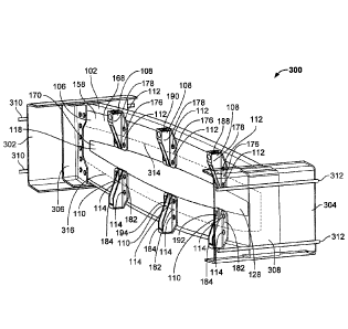
In the illustrated example of FIG. 3, the composite rib 100 is shown in an
assembled
state and coupled to the front spar 302 and the rear spar 304 of the aircraft
wing 300. The first
metallic rib post 306 couples the composite rib 100 to the front spar 302, and
the second
metallic rib post 308 coupled the composite rib 100 to the rear spar 304.
Example first CRN
cables 310 are carried by, coupled to, and/or mounted on the front spar 302,
and example
second CRN cables 312 are carried by, coupled to, and/or mounted on the rear
spar 304. The
first and/or second CRN cables 310, 312 can lead to and/or be operatively
coupled to one or
more discharge probe(s) of the aircraft wing 300 that facilitate dissipating
and/or discharging
electrical current and/or electrostatic charge into the atmosphere.
The first metallic rib post 306 of FIG. 3 is coupled (e.g., bolted, riveted,
etc.) to the
CFRP panel 102 of the composite rib 100 at the first end 120 of the CFRP panel
102. The
second metallic rib post 308 of FIG. 3 is coupled (e.g., bolted, riveted,
etc.) to the CFRP panel
102 of the composite rib 100 at the second end 122 of the CFRP panel 102. When
the
composite rib 100 is coupled to the first and second metallic rib posts 306,
308 as shown in
- 27 -
CA 3067469 2020-01-09
FIG. 3, the border 168 and/or, more generally, the metallic grounding plate
106 contacts the
first and second metallic fittings 108, 110 and further contacts the first and
second metallic rib
posts 306, 308, thereby advantageously providing one or more electrical
grounding paths
passing from the first and/or second metallic fittings 108, 110 to the first
and/or second
metallic rib posts 306, 308 of the composite rib 100.
In the illustrated example of FIG. 3, the border 168 and/or, more generally,
the metallic
grounding plate 106 provides an example first electrical grounding path 314
that extends from
one or more of the first metallic fittings 108 to the first and/or second
metallic rib posts 306,
308. The border 168 and/or, more generally, the metallic grounding plate 106
further provides
an example second electrical grounding path 316 that extends from one or more
of the second
metallic fittings 110 to the first and/or second metallic rib posts 306, 308.
As shown in FIG. 3,
the border 168 of the metallic grounding plate 106 connects the first and
second electrical
grounding paths 314, 316 to one another.
Electrical current (e.g., lightning current from a lightning strike) and/or
electrostatic
charge can be received at the first and/or second metallic fittings 108, 110
of the composite rib
100 from the first and/or second skin panels 402, 404 of the aircraft wing
300. The first and/or
second electrical grounding paths 314, 316 of FIG. 3 can carry and/or pass the
received
electrical current and/or electrostatic charge from the first and/or second
metallic fittings 108,
110 of the composite rib 100 to the first and/or second metallic rib posts
306, 308 of the
composite rib 100. Electrical current and/or electrostatic charge received at
the first metallic
rib post 306 passes from the first metallic rib post 306 through the front
spar 302 to the first
CRN cables 310. Electrical current and/or electrostatic charge received at the
second metallic
rib post 308 passes from the second metallic rib post 308 through the rear
spar 304 to the
- 28 -
CA 3067469 2020-01-09
second CRN cables 312. The first and/or second CRN cables 310, 312 carry
and/or pass the
received electrical current and/or electrostatic charge to one or more
discharge probe(s) of the
aircraft wing 300 that facilitate dissipating and/or discharging electrical
current and/or
electrostatic charge into the atmosphere. Thus, the first and second
electrical grounding paths
314, 316 of the composite rib 100 advantageously assist in carrying, passing
and/or
transferring electrical current and/or electrostatic charge away from the
composite rib 100 and
into the atmosphere.
In the illustrated example of FIG. 4, the composite rib 100 is shown in an
assembled
state and coupled to the upper skin panel 402 and the lower skin panel 404 of
the aircraft wing
300. The hat stiffener 104 is coupled to the CFRP panel 102. The flanges 148
of the hat
stiffener 104 contact the first surface 116 of the CFRP panel 102. The
metallic grounding plate
106 is coupled to the CFRP panel 102. The first surface 156 of the metallic
grounding plate
106 contacts the second surface 118 of the CFRP panel 102. The first (e.g.,
upper) metallic
fitting 108 is coupled to the CFRP panel 102. The plate portion 176 of the
first metallic fitting
108 contacts the second surface 158 of the metallic grounding plate 106. The
second (e.g.,
lower) metallic fitting 110 is coupled to the CFRP panel 102. The plate
portion 182 of the
second metallic fitting 110 contacts the second surface 158 of the metallic
grounding plate 106.
The first (e.g., upper) fasteners 112 extend through the plate portion 176 of
the first metallic
fitting 108, through the metallic grounding plate 106, through the CFRP panel
102, and
through one of the flanges 148 of the hat stiffener 104. The second (e.g.,
lower) fasteners 114
extend through the plate portion 182 of the second metallic fitting 110,
through the metallic
grounding plate 106, through the CFRP panel 102, and through one of the
flanges 148 of the
hat stiffener 104.
- 29 -
CA 3067469 2020-01-09
In the illustrated example of FIG. 4, the assembled composite rib 100 is
coupled to the
upper skin panel 402 of the aircraft wing 300 via the first (e.g., upper)
metallic fitting 108, and
coupled to the lower skin panel 404 of the aircraft wing 300 via the second
(e.g., lower)
metallic fitting 110. The coupling of the assembled composite rib 100 to the
upper skin panel
402 of the aircraft wing 300 via the first metallic fitting 108 is provided in
part by a threaded
engagement between the first bolt 408 and the barrel nut 414. The coupling of
the assembled
composite rib 100 to the lower skin panel 404 of the aircraft wing 300 via the
second metallic
fitting 110 is provided in part by a threaded engagement between the second
bolt 420 and the
retaining nut 422.
Electrical current (e.g., lightning current) and/or electrostatic charge
applied to the
upper skin panel 402 of the aircraft wing 300 is transferred from the upper
skin panel 402 to
the first (e.g., upper) metallic fittings 108 of the composite rib 100, from
the first metallic
fittings 108 through the metallic grounding plate 106 (e.g., via the first
electrical grounding
path 314 of FIG. 3) to the first and/or second metallic rib posts 306, 308,
and from the first
and/or second metallic rib posts 306, 308 through the front and/or rear spars
302, 304 to the
first and/or second CRN cables 310, 312. Electrical current and/or
electrostatic charge applied
to the lower skin panel 404 of the aircraft wing 300 is transferred from the
lower skin panel
404 to the second (e.g., lower) metallic fittings 110 of the composite rib
100, from the second
metallic fittings 110 through the metallic grounding plate 106 (e.g., via the
second electrical
grounding path 316 of FIG. 3) to the first and/or second metallic rib posts
306, 308, and from
the first and/or second metallic rib posts 306, 308 through the front and/or
rear spars 302, 304
to the first and/or second CRN cables 310, 312. The first and/or second CRN
cables 310, 312
carry and/or pass the received electrical current and/or electrostatic charge
to one or more
- 30 -
CA 3067469 2020-01-09
discharge probe(s) of the aircraft wing 300 that facilitate dissipating and/or
discharging
electrical current and/or electrostatic charge into the atmosphere.
FIG. 6 is an exploded view of an example alternate composite rib 600
constructed in
accordance with teachings of this disclosure. FIG. 7 is a perspective view of
the example
alternate composite rib 600 of FIG. 6 in an assembled state. The alternate
composite rib 600 of
FIGS. 6 and 7 includes the CFRP panel 102, the hat stiffeners 104, the
metallic grounding plate
106, the first (e.g., upper) metallic fittings 108, the second (e.g., lower)
metallic fittings 110,
the first (e.g., upper) fasteners 112, and the second (e.g., lower) fasteners
114 of the composite
rib 100 of FIGS. 1-5 described above. The alternate composite rib 600 of FIGS.
6 and 7 can be
coupled to the front and rear spars 302, 304 of the aircraft wing 300 of FIG.
3 via
corresponding ones of the first and second metallic rib posts 306, 308 of FIG.
3 in the same
manner as the composite rib 100 of FIGS. 1-4 is coupled to the front and rear
spars 302, 304 of
the aircraft wing 300 of FIG. 3 via corresponding ones of the first and second
metallic rib posts
306, 308 of FIG. 3, as described above. Moreover, the alternate composite rib
600 of FIGS. 6
and 7 can be coupled to the upper skin panel 402 and the lower skin panel 404
of the aircraft
wing 300 of FIG. 4 in the same manner as the composite rib 100 of FIGS. 1-4 is
coupled to the
upper skin panel 402 and the lower skin panel 404 of the aircraft wing 300 of
FIG. 4, as
described above.
In addition to the above-identified components and/or parts, the alternate
composite rib
600 of FIGS. 6 and 7 further includes example first (e.g., upper) shear ties
602 and example
second (e.g., lower) shear ties 604. In the illustrated example of FIGS. 6 and
7, the alternate
composite rib 600 includes two (2) first shear ties 602, and two (2) second
shear ties 604. In
other examples, the alternate composite rib 600 can include a different number
(e.g., 0, 1, 3,
-31 -
CA 3067469 2020-01-09
etc.) of first shear ties 602, and/or a different number (e.g., 0, 1, 3, etc.)
of second shear ties
604. The first and second shear ties 602, 604 of FIGS. 6 and 7 are structural
and/or load-
bearing members of the alternate composite rib 600. In some examples, the
first and second
shear ties 602, 604 can be CFRP shear ties, and can accordingly be made from
the same
material as the CFRP panel 102 of the alternate composite rib 600. In other
examples, one or
more of the first and second shear ties 602, 604 can alternatively be made
from a material other
than CFRP including, for example, a different plastic material and/or a metal
material.
Respective ones of the first (e.g., upper) shear ties 602 are configured to be
coupled to
the metallic grounding plate 106 between neighboring ones of the first (e.g.,
upper) metallic
fittings 108 of the alternate composite rib 600. Similarly, respective ones of
the second (e.g.,
lower) shear ties 604 are configured to be coupled to the metallic grounding
plate 106 between
neighboring ones of the second (e.g., lower) metallic fittings 110 of the
alternate composite rib
600. For example, as shown in FIG. 7, an example first upper shear tie 606
from among the
first (e.g., upper) shear ties 602 is coupled (e.g., bonded) to the second
surface 158 of the
metallic grounding plate 106 at a location between the first upper metallic
fitting 188 and the
second upper metallic fitting 190 from among the first (e.g., upper) metallic
fittings 108 of the
alternate composite rib 600. As further shown in FIG. 7, an example first
lower shear tie 608
from among the second (e.g., lower) shear ties 604 is coupled (e.g., bonded)
to the second
surface 158 of the metallic grounding plate 106 at a location between the
first lower metallic
fitting 192 and the second lower metallic fitting 194 from among the second
(e.g., lower)
metallic fittings 110 of the alternate composite rib 600. The first and second
shear ties 602,
604 of the alternate composite rib 600 of FIGS. 6 and 7 advantageously enhance
the overall
stability of the alternate composite rib 600 relative to that of the composite
rib 100 of FIGS. 1-
- 32 -
CA 3067469 2020-01-09
4 without compromising and/or impeding the benefits provided by the first and
second
electrical grounding paths 514, 516, which remains fully-operable in the
alternate composite
rib 600.
From the foregoing, it will be appreciated that example aircraft wing
composite ribs
having electrical grounding paths have been disclosed. The disclosed composite
ribs
advantageously include a CFRP panel, a metallic rib post, a metallic fitting,
and a metallic
grounding member (e.g., a metallic grounding plate or a metallic grounding
cable). The
metallic rib post is coupled to the CFRP panel and is configured to be coupled
to a spar of an
aircraft wing, the spar being coupled to a CRN cable. The metallic fitting is
coupled to the
CFRP panel and is configured to be coupled to a skin panel of the aircraft
wing. The metallic
grounding member is positioned between the CFRP panel and the metallic
fitting, thereby
advantageously providing an electrical grounding path that extends from the
metallic fitting to
the metallic rib post. The electrical grounding path enables electrical
current and/or
electrostatic charge to pass from the metallic fitting to the metallic rib
post. The electrical
current and/or electrostatic charge can thereafter pass from the metallic rib
post through the
spar to the CRN cable, thereby allowing for such electrical current and/or
electrostatic charge
to be carried and/or dissipated away from the composite rib and into the
atmosphere. The
electrical grounding path formed by the metallic grounding member of the
example aircraft
wing composite ribs disclosed herein provides enhanced and/or improved
lightning strike
protection without compromising and/or impeding the above-described benefits
associated
with implementing a composite rib having a CFRP panel in lieu of a
corresponding metallic
(e.g., aluminum) panel.
- 33 -
CA 3067469 2020-01-09
In some examples, a composite rib is disclosed. In some disclosed examples,
the
composite rib comprises a CFRP panel. In some disclosed examples, the
composite rib further
comprises a metallic rib post coupled to the CFRP panel and configured to be
coupled to a spar
of an aircraft wing. In some disclosed examples, the spar is coupled to a CRN
cable. In some
disclosed examples, the composite rib further comprises a metallic fitting
coupled to the CFRP
panel and configured to be coupled to a skin panel of the aircraft wing. In
some disclosed
examples, the composite rib further comprises a metallic grounding member
positioned
between the CFRP panel and the metallic fitting. In some disclosed examples,
the metallic
grounding member provides an electrical grounding path extending from the
metallic fitting to
the metallic rib post.
In some disclosed examples, the electrical grounding path is configured to
carry
lightning current from the metallic fitting to the metallic rib post. In some
disclosed examples,
the lightning current is to be received at the metallic fitting from the skin
panel, to pass through
the electrical grounding path, and to pass from the metallic rib post through
the spar to the
CRN cable.
In some disclosed examples, the electrical grounding path is configured to
carry
electrostatic charge from the metallic fitting to the metallic rib post. In
some disclosed
examples, the electrostatic charge is to be received at the metallic fitting
from the skin panel, to
pass through the electrical grounding path, and to pass from the metallic rib
post through the
spar to the CRN cable.
In some disclosed examples, the metallic grounding member is a non-structural
member.
- 34 -
CA 3067469 2020-01-09
In some disclosed examples, the metallic fitting is a first metallic fitting,
the skin panel
is an upper skin panel, and the electrical grounding path is a first
electrical grounding path. In
some disclosed examples, the composite rib further comprises a second metallic
fitting coupled
to the CFRP panel and configured to be coupled to a lower skin panel of the
aircraft wing. In
some disclosed examples, the metallic grounding member is further positioned
between the
CFRP panel and the second metallic fitting. In some disclosed examples, the
metallic
grounding member provides a second electrical grounding path extending from
the second
metallic fitting to the metallic rib post.
In some disclosed examples, the metallic grounding member is a metallic
grounding
plate.
In some disclosed examples, the metallic grounding plate includes a border and
an
opening surrounded by the border. In some disclosed examples, the opening is
located
between the first and second metallic fittings. In some disclosed examples,
the first and second
metallic fittings contact the border. In some disclosed examples, the border
connects the first
and second electrical grounding paths.
In some disclosed examples, the metallic grounding plate includes a first
surface and a
second surface located opposite the first surface. In some disclosed examples,
the first surface
contacts the CFRP panel. In some disclosed examples, the second surface
contacts the first and
second metallic fittings.
In some disclosed examples, the composite rib further comprises a hat
stiffener coupled
to the CFRP panel.
In some disclosed examples, the CFRP panel includes a first surface and a
second
surface located opposite the first surface. In some disclosed examples, the
hat stiffener
- 35 -
CA 3067469 2020-01-09
contacts the first surface of the CFRP panel, and the metallic grounding plate
contacts the
second surface of the CFRP panel.
In some disclosed examples, the hat stiffener is bonded to the first surface
of the CFRP
panel. In some disclosed examples, the metallic grounding plate is bonded to
the second
surface of the CFRP panel.
In some disclosed examples, the CFRP panel further includes a central segment
defining a plane, a first flange extending away from the central segment at a
first angle relative
to the plane, and a second flange extending away from the central segment at a
second angle
relative to the plane. In some disclosed examples, the hat stiffener is
located between the first
flange and the second flange.
In some disclosed examples, the composite rib further comprises a first
fastener
extending through the first metallic fitting, the metallic grounding plate,
the CFRP panel, and
the hat stiffener. In some disclosed examples, the composite rib further
comprises a second
fastener extending through the second metallic fitting, the metallic grounding
plate, the CFRP
panel, and the hat stiffener.
In some disclosed examples, the first metallic fitting is a first upper
metallic fitting and
the second metallic fitting is a first lower metallic fitting. In some
disclosed examples, the
composite rib further comprises a second upper metallic fitting coupled to the
CFRP panel and
configured to be coupled to the upper skin panel, the second upper metallic
fitting being spaced
apart from the first upper metallic fitting. In some disclosed examples, the
composite rib
further comprises a second lower metallic fitting coupled to the CFRP panel
and configured to
be coupled to the lower skin panel, the second lower metallic fitting being
spaced apart from
the first lower metallic fitting. In some disclosed examples, the composite
rib further
- 36 -
CA 3067469 2020-01-09
comprises a first shear tie coupled to the metallic grounding plate at a
location between the first
and second upper metallic fittings. In some disclosed examples, the composite
rib further
comprises a second shear tie coupled to the metallic grounding plate at a
location between the
first and second lower metallic fittings.
In some examples, a method for assembling a composite rib is disclosed. In
some
disclosed examples, the method comprises coupling a metallic grounding member
to a CFRP
panel. In some disclosed examples, the method further comprises coupling a
metallic rib post
to the CFRP panel. In some disclosed examples, the metallic rib post is
configured to be
coupled to a spar of an aircraft wing. In some disclosed examples, the spar is
coupled to a
CRN cable. In some disclosed examples, the method further comprises coupling a
metallic
fitting to the CFRP panel. In some disclosed examples, the metallic fitting is
configured to be
coupled to a skin panel of the aircraft wing. In some disclosed examples of
the method, the
metallic grounding member is positioned between the CFRP panel and the
metallic fitting, and
the metallic grounding member provides an electrical grounding path extending
from the
metallic fitting to the metallic rib post.
In some disclosed examples, the metallic fitting is a first metallic fitting,
the skin panel
is an upper skin panel, and the electrical grounding path is a first
electrical grounding path. In
some disclosed examples, the method further comprises coupling a second
metallic fitting to
the CFRP panel. In some disclosed examples, the second metallic fitting is
configured to be
coupled to a lower skin panel of the aircraft wing. In some disclosed
examples, the metallic
grounding member is further positioned between the CFRP panel and the second
metallic
fitting, and the metallic grounding member provides a second electrical
grounding path
extending from the second metallic fitting to the metallic rib post.
- 37 -
CA 3067469 2020-01-09
In some disclosed examples, the metallic grounding member is a metallic
grounding
plate.
In some disclosed examples, the metallic grounding plate includes a border and
an
opening surrounded by the border. In some disclosed examples, the opening is
located
between the first and second metallic fittings. In some disclosed examples,
the first and second
metallic fittings contact the border. In some disclosed examples, the border
connects the first
and second electrical grounding paths.
In some disclosed examples, the method further comprises coupling a hat
stiffener to
the CFRP panel.
In some disclosed examples, the CFRP panel includes a first surface and a
second
surface located opposite the first surface. In some disclosed examples, the
hat stiffener
contacts the first surface of the CFRP panel, and the metallic grounding plate
contacts the
second surface of the CFRP panel.
In some disclosed examples, the coupling the hat stiffener to the CFRP panel
includes
bonding the hat stiffener to the first surface of the CFRP panel. In some
disclosed examples,
the coupling the metallic grounding plate to the CFRP panel includes bonding
the metallic
grounding plate to the second surface of the CFRP panel.
In some disclosed examples, the coupling the first metallic fitting to the
CFRP panel
includes extending a first fastener through the first metallic fitting, the
metallic grounding
plate, the CFRP panel, and the hat stiffener. In some disclosed examples, the
coupling the
second metallic fitting to the CFRP panel includes extending a second fastener
through the
second metallic fitting, the metallic grounding plate, the CFRP panel, and the
hat stiffener.
- 38 -
CA 3067469 2020-01-09
In some examples, a metallic fitting configured to couple a composite rib to a
skin
panel of an aircraft wing is disclosed. In some disclosed examples, the
metallic fitting
comprises a through hole configured to receive a fastener, the fastener
configured to couple the
metallic fitting to the composite rib. In some disclosed examples, the
metallic fitting further
comprises a bore configured to receive a bolt. In some disclosed examples, the
metallic fitting
further comprises a cavity intersecting the bore, the cavity having an access
opening. In some
disclosed examples, the metallic fitting further comprises a barrel nut
located within the cavity,
the barrel nut configured to threadably engage the bolt to couple the metallic
fitting to the skin
panel. In some disclosed examples, the metallic fitting further comprises a
seal located within
the cavity, the seal configured to close the access opening.
In some disclosed examples, the through hole is orthogonal to the bore.
In some disclosed examples, the metallic fitting further comprises a plate
portion and a
rib portion extending away from the plate portion.
In some disclosed examples, the through hole is formed in the plate portion.
In some disclosed examples, the bore is formed in the rib portion. In some
disclosed
examples, the bore does not extend fully through the rib portion.
In some disclosed examples, the cavity is formed in the rib portion. In some
disclosed
examples, the cavity does not extend fully through the rib portion.
In some disclosed examples, the seal is configured to prevent sparks from
passing out
of the cavity through the access opening.
In some disclosed examples, the seal is configured to interface with fuel
contained
within the aircraft wing.
- 39 -
CA 3067469 2020-01-09
In some examples, a method for coupling a composite rib to a skin panel of an
aircraft
wing via a metallic fitting is disclosed. In some disclosed examples, the
method comprises
extending a fastener through a through hole of the metallic fitting to couple
the metallic fitting
to the composite rib. In some disclosed examples, the method further comprises
extending a
bolt into a bore of the metallic fitting to couple the metallic fitting to the
skin panel. In some
disclosed examples, the bolt threadably engages a barrel nut located within a
cavity of the
metallic fitting. In some disclosed examples, the cavity intersects the bore
and has an access
opening. In some disclosed examples, the access opening is closed by a seal
located within the
cavity.
In some disclosed examples of the method, the through hole is orthogonal to
the bore.
In some disclosed examples of the method, the metallic fitting includes a
plate portion
and a rib portion extending away from the plate portion.
In some disclosed examples of the method, the through hole is formed in the
plate
portion.
In some disclosed examples of the method, the bore is formed in the rib
portion. In
some disclosed examples, the bore does not extend fully through the rib
portion.
In some disclosed examples of the method, the cavity is formed in the rib
portion. In
some disclosed examples, the cavity does not extend fully through the rib
portion.
In some disclosed examples of the method, the seal is configured to prevent
sparks
from passing out of the cavity through the access opening.
In some disclosed examples of the method, the seal is configured to interface
with fuel
contained within the aircraft wing.
- 40 -
CA 3067469 2020-01-09
Although certain example methods, apparatus and articles of manufacture have
been
disclosed herein, the scope of coverage of this patent is not limited thereto.
On the contrary,
this patent covers all methods, apparatus and articles of manufacture fairly
falling within the
scope of the claims of this patent.
- 41 -
CA 3067469 2020-01-09