Note: Descriptions are shown in the official language in which they were submitted.
CA 03067739 2019-12-17
WO 2019/004948 PCT/SK2018/050009
1
Expandable container shelter
Technical Field
[0001] The technical solution relates to expandable container shelters,
particularly
those which use transportation container as a container, for example made
on the basis of intermodal container, also known as the ISO container,
with lengths of 6 m and 12 m, 20 ft and 40 ft, respectively. More
particularly, the technical solution relates to mentioned expandable
container shelters, those which include parts for the construction of a
shelter structure associated with this container that are connected to the
container and stored in this container during its transportation and storage.
Background Art
[0002] Extendable or expandable containers are standard product, mainly used
for field applications as mobile hospital buildings, but also as
accommodation, administrative or service units. In the case of extendable
containers, lateral extension is approximately equal to the width of the
container and as the container is usually extended to both sides, resulting
object, including the container, is thereby substantially three times as wide
as the container itself.
[0003] In the case of expandable containers, one or both of the longitudinal
walls
of the container are usually lowered, where the lowered wall at the same
time serves as a floor for the shelter extension of the container. Such
shelter is then formed by a cover, supported by a metal or inflatable
structure. In this case, the lateral extension is approximately equal to the
height of the container, and as the container is usually such expanded
along both longitudinal sides, resulting shelter/building has thereby the
width of the container substantially increased by double the height of the
container.
[0004] Expandable container shelter having inflatable structure of the shelter
is
disclosed for example in W02017/048777 Al.
CA 03067739 2019-12-17
WO 2019/004948 PCT/SK2018/050009
2
[0005] With regard to the fact that the above mentioned solutions provide
extension of existing container space practically only by double the width
or the height of the container, if there is a requirement for larger place to
be covered, as for example patient ward of a field hospital, separate tents
or other shelters have to be connected to the container.
[0006] Creating larger space associated with the container using elements
which
forms a part of the container in its transportation or storage configuration
is
partially solved by W02014/082104 Al. This document discloses a
structure which includes a container which forms a housing and, mounted
to the housing a plurality of walls which are pivotally interconnected and
which are movable between a compact stored configuration and an
extended operative configuration. These walls are being extended from
longitudinal sides of the container by means of vertical hinging supports at
the ends of the longitudinal sides of the container and vertical pivotal
supports with which the walls are mutually connected. This solution allows
for enclosing larger area, however, if this area is to be covered, said walls
cannot be used as supporting for attaching a roof supports. Roof support,
in this case a canvas, is provided in this solution in the form of a mast
embedded in the ground and centrally positioned within the enclosure
formed by the walls. Then, the canvas is stretched from the mast, and
attached to the walls.
[0007] Object of this solution is to provide improved expandable container
shelter,
entirely transportable and storable in single container, which is able to
provide maximum possible covered area when the container is expanded
to its working configuration, without a need for adding external elements
not comprised within this container. Proposed solution maximizes
applicability of expandable container shelters.
Disclosure of Invention
[0008] Said object is fulfilled by expandable container shelter, particularly
such
that uses transportation container as a container, for example made on the
basis of intermodal container, also known as the ISO container, with
lengths of 6 m and 12 m, 20 ft and 40 ft, respectively, where this container
CA 03067739 2019-12-17
WO 2019/004948 PCT/SK2018/050009
3
comprises elements pivotally connected to the container in vertical mounts
at the ends of longitudinal side of the container, provided for creating a
structure designed for extending the inner space of the container to a
shelter connected with this container at the longitudinal side of the
container. Expandable container shelter according to this technical
solution is characterized in that elements provided for creating the
structure designed for extending the inner space of the container to the
shelter connected with this container are at least on one longitudinal side
of the container composed of one pair of supporting frames. The
supporting frame comprises at least one horizontal beam and has length in
the range up to dimension equal to inner length of the container. The
shelter roof supports are then connected to said supporting frames.
A connection of the roof supports to the supporting frame is of course
understood also the connection of these supports to the supporting frame
through other elements which can be present on this frame and can form a
part of said supporting frame, such as various auxiliary beams, slats,
shaped mounts, profile anchors and similar.
[0009] In order to improve and support positioning of the supporting frames,
it is
preferred that the supporting frame is at least at one point of its length
from its pivotal mount in the container provided by a member for securing
its horizontal position.
[0010] In order to create the shelter space enclosed from all sides, or to
provide
transversal reinforcement of the supporting frames, it is preferred that an
auxiliary frame for providing transversal connection of the supporting
frames in their opened position is mounted on the supporting frame in the
area of its end opposite to its pivotal mount in the container. Then the
shelter roof supports can be oriented in direction transversal to the length
of the container, whereby they are connected to the auxiliary frame and
the container. The auxiliary frame in its folded position can be inserted in
the supporting frame in order to save space.
[0011] Supporting frames can be placed inside the container in one plane,
whereby applies that maximal sum of lengths of the supporting frames is
equal to the value of the inner length of the container; in other words
CA 03067739 2019-12-17
WO 2019/004948 PCT/SK2018/050009
4
maximal value of the sum of lengths of the supporting frames is equal to
the value of the inner length of the container.
[0012] Further, the supporting frames can be placed inside the container in
different planes, whereby maximal length of single supporting frame can
be equal up to the value of the inner length of the container.
[0013] It is preferred, when the shelter roof supports are inflatable beams.
Then,
in regard of handling, it is further preferred when the inflatable beams are
permanently connected to at least one supporting frame or to the
container.
[0014] With regard to maintaining original dimensions of the container,
particularly
ISO container, that is important for managing of standardized
transportation of containers, it is preferred when the supporting frame, the
auxiliary frame, roof supports and roof are in transport or storage
configuration of the container placed in the inner space of the container
such that they do not project out over the outline of the container.
Brief Description of Drawings
[0015] The technical solution further described in examples of embodiments is
depicted in attached drawings schematically showing on:
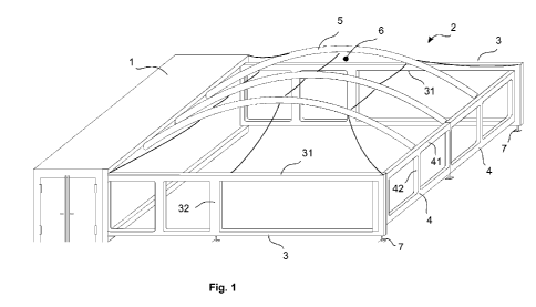
Fig. 1 - expandable container shelter according to this technical solution in
expanded configuration, with inflatable beams of shelter roof supports
arranged in direction transversal to the length of the container;
Fig. 2 - expandable container shelter according to this technical solution in
expanded configuration, with inflatable beams of shelter roof supports
arranged in direction accordant to the length of the container;
Fig. 3 - expandable container shelter according to this technical solution in
expanded configuration, with shelter roof supports connected to the
supporting frames, with a roof placed between said roof supports by
means of Keder slid into a luff groove in the roof supports;
Fig. 4 - expandable container shelter according to this technical solution in
expanded configuration, with shelter roof supports connected to the
supporting frames, with a roof suspended under said roof supports;
Fig. 5 - expandable container shelter according to this technical solution in
CA 03067739 2019-12-17
WO 2019/004948 PCT/SK2018/050009
expanded configuration, with folding roof with solid bars sliding over the
length of the supporting frames;
Fig. 6 - expandable container shelter according to this technical solution in
closed configuration;
Fig. 7 - expandable container shelter according to this technical solution in
position of partially unfolded supporting frames and auxiliary frames, thus
in the phase of unfolding the shelter from the container;
Fig. 8 - expandable container shelter according to this technical solution in
fully expanded configuration of the supporting frames and the auxiliary
frames, thus in the phase before installation of a roof;
Fig. 9 - particular structure variant of the supporting frames and the
auxiliary frames of the expandable container shelter according to this
technical solution with vertically reinforced horizontal beams;
Fig. 10 - particular structure variant of the supporting frames of the
expandable container shelter according to this technical solution with
vertically reinforced horizontal beams;
Fig. 11 - particular structure variant of the supporting frames of the
expandable container shelter according to this technical solution with pair
of single horizontal beams at one supporting frame;
Fig. 12- particular structure variant of the supporting frames of the
expandable container shelter according to this technical solution with
a single horizontal beam at one supporting frame;
Fig. 13 - particular structure variant of the supporting frames of the
expandable container shelter according to this technical solution for
placing the supporting frames into the container in one plane, where both
the supporting frames have the same length;
Fig. 14- particular structure variant of the supporting frames of the
expandable container shelter according to this technical solution for
placing the supporting frames into the container in one plane, where both
the supporting frames have the same length, with elongating parts for
increasing the length after unfolding the supporting frames from the
container.
CA 03067739 2019-12-17
WO 2019/004948 PCT/SK2018/050009
6
Mode(s) for Carrying Out the Invention
[0016] Further described examples of embodiments of expandable container
shelters according to this technical solution refer to Fig.1 to Fig. 14. Said
figures show shelters 2, or their parts on one side of a container 1,
however, these figures, at the same time, illustrate also examples of
embodiments with the shelters 2 at both sides of the container 1 because
_ _
building of the shelter 2 at the other side of the container 1 is in fact
analogous.
[0017] In general, embodiment of the expandable container shelter according to
this technical solution, which is the most preferred in regard of maximal
area covered and handling, comprises the container 1, two pairs of
horizontally swivelling supporting frames 3 comprising auxiliary swivelling
frames 4 and two roofs 6, attached on inflatable beams 5, where one pair
_ _ _
of swivelling supporting frames 3 together with one roof 6 attached on the
inflatable beams 5 is placed at one long side of the container 1, and the
_ _
other pair of the swivelling frames 3 together with the other roof 6 attached
on the inflatable beams 5 is placed at the opposite long side of the
_
container 1. In this way, symmetrical, sufficiently rigid structure composed
_
of the container 1 and two shelters 2 placed by long sides of said container
_ _
1 is created.
_
[0018] Further, generally the most preferred position of opened supporting
frames
3 is mutually parallel and perpendicular to the container 1. However, it is
_ _
possible also to create an object of different shape, for example
trapezoidal or rhombic, by applying different lengths of the supporting
frames 3.
_
[0019] The first example of embodiment of the expanded container shelter
according to this technical solution described hereinafter, is shown in
Fig. 1 and Fig. 2.
[0020] Pair of supporting frames 3 is mounted in vertical pivotal mounts on
the
opposite ends of the container 1 on each longitudinal side of the
container 1. Specifically, each one of the supporting frames 3 is with its
_ _
one end mounted in one pivotal mount. Each supporting frame 3
comprises a pair of horizontal beams 31 with vertical reinforcements 32
CA 03067739 2019-12-17
WO 2019/004948 PCT/SK2018/050009
7
and auxiliary frames 4 at free ends of the supporting frames 3. These
auxiliary frames 4 have in this example similar structure as supporting
frames 3, thus comprise a pair of horizontal beams 41 with vertical
_
reinforcements 42. This particular arrangement of supporting frames 3 and
_ _
auxiliary frames 4 is shown in Fig. 9.
[0021] In closed configuration, the supporting frames 3 are placed inside the
container 1 in different planes and thus maximal length of one supporting
_
frame 3 can practically be equal to dimension of the inner length of the
_
container 1. The auxiliary frame 4 of the supporting frame 3 is in this
example provided such that it does not project out over the thickness of
the supporting frame 3. This is advantageous in regard of space saving
when the supporting frame 3 is folded. The auxiliary frame 4 is in this
example pivotally mounted in the supporting frame 3 by its one edge.
Length of the auxiliary frame 4 is in this example equal to half of the
distance between the supporting frames 3 in opened working position, i.e.
when unfolded supporting frames 3 are parallel.
[0022] After setting up the container 1 at desired place, supporting frames 3
are
one after the other opened. Afterwards, the auxiliary frames 4 are unfolded
from these frames 3. It is preferred to secure opened supporting frames 3,
_ _
and if appropriate, also the auxiliary frames 4 in their pivotal mounts. It is
possible the structure such created further preferably stabilize by
connecting the ends of the auxiliary frames 4 with members 7 for securing
of horizontal position of the supporting frames 3 and/or the auxiliary
frames 4, which can be commonly used, preferably height-adjustable,
_
supports, legs, baseplates, and similar, or also wheels, runners and
similar, which can help even during the step of unfolding of the frames 3,
4. This structure, if necessary, can be further strengthened also using
_
corner reinforcements 9 which can stabilize the frames 3, 4 against each
_
other, or the supporting frames 3 against the container 1, or diagonal
reinforcements 33, 43 which reinforce the frames 3, 4 individually. Said
steps are schematically shown in Fig. 6, 7 and 8. Sides of the frames 3, 4
can be preferably in advance covered by solid or flexible material, thereby
preparing walls of future object and saving time for installation.
CA 03067739 2019-12-17
WO 2019/004948 PCT/SK2018/050009
8
[0023] Afterwards, said structure is ready for installation of the roof 6. The
roof 6
comprises, in this example, beam 5 which are at one end connected to the
container 1 and at the other end to the auxiliary frames 4, as shown in
_ _
Fig. 1, or the beams 5 are connected to opposite supporting frames 3, as
shown in Fig. 2. In this example of embodiment, roof 6 supports 5 are
arcuate inflatable beams. The roof 6 is conventionally of canvas type,
_
made of flexible material, or combination of flexible and not flexible
material, preferably impregnated or coated fabric.
[0024] Making use of arcuate inflatable beams as roof 6 supports 5 is very
advantageous due to following reasons.
[0025] The arcuate inflatable beam 5 is easily transportable, folded or
rolled,
_
together with the shelter 2 roof 6. The beam 5 can be permanently
connected with material of the roof 6. Folded or rolled roof 6 including
_ _
deflated beams 5 can be stored in the container 1 separately.
_ _
[0026] Preferably it is however possible to connect at least one side of the
roof 6
together with one side of the roof beams 5 permanently to the container 1,
in the case the beams 5 are arranged in direction transversal to the length
_
of the container 1; or the beams 5 can be permanently connected to at
_ _
least one supporting frame 3 in the case when the beams 5 are arranged
in direction accordant to the length of the container 1.
[0027] During transportation, folded roofs 6 together with deflated beams 5
are
contained inside the container 1. One side of deflated beams 5 is then
_ _
preferably suspended under a ceiling of the container 1 in holders, for
example in guiding grooves, to be possible for the ends of the beams to be
easily moved to the edge of the container 1, i.e. to working position, when
the shelter 2 roof 6 is being assembled.
_ _
[0028] Remaining part of the beams 5 and the roofs 6 is then hanging folded
under the ceiling of the container 1, or this part of the beams 5 and roofs 6
is lying folded at the bottom of the container 1 and only a part of said
beams 5 and roofs 6 corresponding approximately to the height of the
_ _
container is hanging. It is preferred to suspend the roofs 6 completely,
because a space is then left at the bottom of the container 1 for storing of
other possible parts of the shelters 2, for example floor, or if necessary
CA 03067739 2019-12-17
WO 2019/004948 PCT/SK2018/050009
9
auxiliary inflatable tent, as well as technical equipment such as air
conditioning unit, power generators or air compressor that can be used
also for inflating the beams 5. Said arrangement is not shown in figures, as
it is sufficiently clearly described and conceivable.
[0029] The roofs 6 such placed and accessories are during transportation thus
_
practically situated in central part of the container 1 and closed by pair of
supporting frames 3 from both sides. It is preferred, in order to maintain
standard dimensions of the container 1, especially in the case of ISO
_
container, when outer side of the outer supporting frame 3 does not project
out over the outline of the container 1.
_
[0030] After the roof 6 with beams 5 is unfolded, free end of the beams 5 is
attached, with known anchoring members, to the opposite side of the
structure, i.e. to the auxiliary frames 4, or to the opposite supporting
frame 3. Afterwards, the roof 6 is attached on the periphery with commonly
_ _
available attaching means used for canvas type roofs, usually to the edges
of the shelter 2 structure, which are in this case the container 1, supporting
_ _
frames 3 and auxiliary frames 4. Possible ways of attaching of roof 6
_ _ _
periphery vary upon requirements for water-proofing, air-proofing, time of
installation and other conditions, while their embodiment, if it is over the
entire periphery, does not influence functionality of the assembly itself.
[0031] In the case, a floor is also a part of the container 1, preferably
coiled on a
roll inside the container 1 it is unrolled as the first to protect the roof 6
_, _
against dirtying of its inner side. Afterwards, the roof 6 is unfolded on the
floor and further work continues as described in preceding paragraph.
[0032] Roof beams 5 are then inflated, thereby stretching the roof and
strengthening the entire structure of the shelter 2. Inflating the beams 5 is
carried out in known ways form known sources of compressed air, for
example by means of standardized compressor hoses and connectors
from a compressor or air cylinder, if appropriate by means of electric
blower and similar.
[0033] It is not necessary, however appropriate for the sake of thoroughness,
to
mention that when building the shelters 2 on both sides of the container 1,
it is advisable to at least open the supporting frames 3 from the container 1
CA 03067739 2019-12-17
WO 2019/004948 PCT/SK2018/050009
on both sides of the container 1 simultaneously due to optimal mass
_
balance.
[0034] Short sides of the container 1, that is front and rear walls, can be
provided
by swivelling wall serving as access floor, onto which an inflatable tent can
be folded during transportation, or they can be provided by regular access
doors, or technical equipment can be placed onto one of the sides, either
permanently placed outside on holders, or during transportation, placed
inside the container 1 and closed by the wall of the transportation
_
container.
[0035] Another example of embodiment of expandable container shelter
according to this technical solution described hereinafter is shown in Fig. 3
and Fig. 4. In this example of embodiment, the bottom structure of the
shelter 2 composed basically of the container 1, supporting frames 3 and
_ _ _
auxiliary frames 4, is substantially identical with that as described above in
the example of embodiment according to Fig. 1 and Fig. 2. Instead of
inflatable beam 5, the support 5 is provided as solid beam. Various knows
_ _
forms of arcuate, bent or straight beams, made of metal, composite, wood,
or other suitable material can be used as the solid beam 5.
_
[0036] In the case of use of solid beams 5, arcuate or bent, which upper edge
is
longer than roof span, that is the distance between longitudinal edge of the
container 1 and auxiliary frames 4, or between the supporting frames 3,
_ _ _
i.e. arcutate or bent beams, it is expected that material of the roof 6 folded
or rolled separately without the beams 5.
[0037] During installation of the roof 6, the beams 5 are attached to the
bottom
structure of the shelter 2 and the roof 6 is stretched upon their surface, or
_ _
in suspended configuration, the roof 6 is pulled to the beam 5, or the
beams 5 are installed from the underside as the last ones and the entire
_
roof 6 is stretched by pushing the beams 5 into their given position on the
_ _
bottom structure of the shelter 2. Also, as schematically shown in Fig. 3,
_
the roof 6 can be installed between the beams 5 by means of Keder slid
_ _
into a luff groove provided in the beams 5. These mentioned ways of
installation of the roof 6 can also be similarly used with the inflatable
_
beams 5.
_
CA 03067739 2019-12-17
WO 2019/004948 PCT/SK2018/050009
11
[0038] Another example of embodiment of expandable container shelter
according to this technical solution described hereinafter is shown in Fig. 5
[0039] In this example, straight beams 5 are used whose upper edge has
approximately the same length as is the roof 6 span, that is in this example
the distance between the supporting frames 3. The roof 6 is permanently
attached to the beams 5 and is stored inside the container in folded or so
_
called accordion shape. In such case, installation would be most
preferably carried out by unfolding the roof 6 by means of a guiding rail or
groove in the supporting frames 3 guiding the ends of straight beams 5.
[0040] In this example of embodiment, the supporting frames 3 can be shaped as
shown in Fig. 12. It is preferred then, in order to increase rigidity of such
structure to provide the supporting frames 3 at their end with members 7
for securing their horizontal position, e.g. in the form of legs.
[0041] Further, in this example of embodiment according to Fig. 5, in the case
of
connecting of free ends of the supporting frames 3 with the auxiliary
frame 4 at least in the form of horizontal beam 41, the roof supports 5 can
_ _ _
be arranged parallel to the supporting frame 3. Then, the roof 6 would
unfold by means of guiding rail or groove on the container 1 and the
auxiliary frame 4.
[0042] Example of embodiment of expandable container shelter according to this
technical solution, where the supporting frames 3 are placed in closed
configuration inside the container 1 in one plane and maximal value of the
sum of lengths of the supporting frames 3 is equal to the value of the inner
length of the container 1, is shown in Fig. 13 and Fig. 14.
[0043] In the example of embodiment shown, length of the supporting frame 3 is
equal to the half of the inner length of the container 1. The supporting
frames 3 can be provided as extendable. It means that sliding extension
_
part 8 is slid in the supporting frame 3, which, after the supporting frame 3
is opened, slides out and extends the supporting frame 3 by the length of
this extension part 8. This particular embodiment is shown in Fig. 14.
[0044] Above described examples of embodiments shown on attached drawings
do not exhaust all possibilities of embodiments of expandable container
shelter according to this technical solution. Other embodiments of
CA 03067739 2019-12-17
WO 2019/004948
PCT/SK2018/050009
12
expandable container shelter within the idea of this technical solution and
in the scope of the claims can be provided by further combining described
parts and their arrangements. Such embodiments can be provided upon
requirements for placement or use of the expandable container shelter in
particular real-life situations.