Note: Descriptions are shown in the official language in which they were submitted.
CA 03068120 2019-12-20
ELECTRONIC DEVICE AND METHOD FOR WIRELESS
COMMUNICATIONS
[0001] The present application claims priority to Chinese Patent Application
No.
201710523258.3, titled "ELECTRONIC DEVICE AND METHOD FOR WIRELESS
COMMUNICATIONS", filed on June 30, 2017 with the China National Intellectual
Property Administration, which is incorporated herein by reference in its
entirety.
FIELD
[0002] The present disclosure generally relates to the technical field of
wireless
communications, in particular to resource allocation for device to device
(D2D)
communication, and in more particular to an electronic apparatus and method
for
wireless communications.
BACKGROUND
[0003] D2D communication is a communication manner for performing direct
communication between user terminals without via a base station or other core
networks, and is one of critical technologies for 5G wireless communications.
According to a frequency band used by the D2D communication, the D2D
communication may be classified into in-band D2D communication and out-band
D2D communication, as shown in Figure 1. Specifically, the out-band D2D
communication uses spectrum resources on an unlicensed frequency band, such as
spectrum on the Industrial Scientific Medical (ISM) frequency band, and the in-
band
D2D communication uses spectrum resources on a licensed frequency band, which
has an advantage of being controlled conveniently. The in-band D2D
communication
may be classified into D2D communication in a multiplexing mode (Underlay D2D)
and D2D communication in a dedicated mode (Overlay D2D). Specifically, the D2D
communication in the multiplexing mode shares resources with other cellular
users,
thereby achieving higher spectrum utilization efficiency, while the D2D
communication in the dedicated mode uses resources allocated by the system
exclusively for it. The D2D communication in the multiplexing mode may be
further
- 1 -
CA 03068120 2019-12-20
classified into D2D communication of multiplexing uplink resources and D2D
communication of multiplexing downlink resources.
[0004] Compared with conventional cellular networks, the D2D user may
multiplex
spectrum resources of a cellular user, such that a higher data transmission
rate,
resource utilization efficiency, network capacity and energy efficiency can be
achieved. However, the D2D communication in the multiplexing mode may incur
more complex electromagnetic interference conditions.
SUMMARY
[0005] In the following, an overview of the present disclosure is given simply
to
provide basic understanding to some aspects of the present disclosure. It
should be
understood that this overview is not an exhaustive overview of the present
disclosure.
It is not intended to determine a critical part or an important part of the
present
disclosure, nor to limit the scope of the present disclosure. An object of the
overview
is only to give some concepts in a simplified manner, which serves as a
preface of a
more detailed description described later.
[0006] According to an aspect of the present disclosure, an electronic
apparatus
for wireless communications is provided, which includes processing circuitry
configured to: for each candidate resource block, acquire a first receiving
signal
measured by a respective cellular user equipment with respect to a pilot
symbol
transmitted by a base station on the candidate resource block in a state that
a D2D
communication group does not perform D2D communication, and a second receiving
signal measured by the respective cellular user equipment with respect to the
pilot
symbol in a state that the D2D communication group performs D2D communication,
respectively; remove an impact of the first receiving signal from the second
receiving
signal, to be used as an interference signal received by the cellular user
equipment
from a D2D emitting device of the D2D communication group; and determine a
priority order for resource blocks available to the D2D communication group by
taking minimization of the interferences as an optimization objective.
[0007] According to another aspect of the present disclosure, a method for
wireless
communications is provided, which includes: for each candidate resource block,
- 2 -
CA 03068120 2019-12-20
acquiring a first receiving signal measured by a respective cellular user
equipment
with respect to a pilot symbol transmitted by a base station on the candidate
resource
block in a state that a D2D communication group does not perform D2D
communication, and a second receiving signal measured by the respective
cellular
user equipment with respect to the pilot symbol in a state that the D2D
communication group performs D2D communication, respectively; removing an
impact of the first receiving signal from the second receiving signal, to be
used as an
interference signal received by the cellular user equipment from a D2D
emitting
device of the D2D communication group; and determining a priority order for
resource blocks available to the D2D communication group by taking
minimization of
the interferences as an optimization objective.
[0008] According to an aspect of the present disclosure, an electronic
apparatus for
wireless communications is provided, which includes: a receiving unit,
configured to
receive, from a base station, an instruction to perform temporary D2D
communication; and a transmitting unit, configured to transmit a pilot symbol
on a
candidate resource block.
[0009] According to another aspect of the present disclosure, a method for
wireless
communications is provided, which includes: receiving, from a base station, an
instruction to perform temporary D2D communication; and transmitting a pilot
symbol on a candidate resource block.
100101 According to other aspects of the present disclosure, computer program
codes and computer program products for implementing the above methods as well
as
computer readable storage medium on which computer program codes for
implementing the above methods are recorded are further provided.
100111 With the electronic apparatus and method according to the present
disclosure, interferences of D2D communication to a cellular user equipment
are
acquired by determining a difference between a receiving signal of the
cellular user
equipment with respect to a pilot symbol in a state that the D2D communication
is not
performed and a receiving signal of the cellular user equipment with respect
to the
pilot symbol in a state that the D2D communication is performed, such that
resource
allocation for D2D communication can be optimized based on the interferences,
thereby improving utilization efficiency of the transmission resources.
- 3 -
CA 03068120 2019-12-20
[0012] These and other advantages of the present disclosure will be more
apparent
by illustrating in detail a preferred embodiment of the present disclosure in
conjunction with accompanying drawings below.
BRIEF DESCRIPTION OF THE DRAWINGS
[0013] To further set forth the above and other advantages and features of the
present disclosure, detailed description will be made in the following taken
in
conjunction with accompanying drawings in which identical or like reference
signs
designate identical or like components. The accompanying drawings, together
with
the detailed description below, are incorporated into and form a part of the
specification. It should be noted that the accompanying drawings only
illustrate, by
way of example, typical embodiments of the present disclosure and should not
be
construed as a limitation to the scope of the disclosure. In the accompanying
drawings:
[0014] Figure 1 is a schematic diagram showing classifications of the D2D
communication;
[0015] Figure 2 shows an example of a scenario in which the D2D communication
multiplexes downlink resources for cellular communication;
[0016] Figure 3 is a schematic diagram showing a basic flow of resource
allocation
for a D2D user;
[0017] Figure 4 shows another example of the scenario in which the D2D
communication multiplexes downlink resources for cellular communication;
[0018] Figure 5 shows an example of a structure of an LTE downlink resource
block;
[0019] Figure 6 is a block diagram showing functional modules of an electronic
apparatus for wireless communications according to an embodiment of the
present
disclosure;
[0020] Figure 7 is a block diagram showing functional modules of an electronic
apparatus for wireless communications according to another embodiment of the
present disclosure;
- 4 -
CA 03068120 2019-12-20
[0021] Figure 8 is a schematic diagram showing a pilot multiplexing manner
among
multiple D2D emitting devices;
[0022] Figure 9 shows an example of a resource link table;
[0023] Figure 10 shows another example of the resource link table;
[0024] Figure 11 is a schematic diagram showing an information procedure
between the base station and the user equipment;
[0025] Figure 12 is a block diagram showing functional modules of an
electronic
apparatus for wireless communications according to another embodiment of the
present disclosure;
[0026] Figure 13 is a flowchart showing a method for wireless communications
according to an embodiment of the present disclosure;
[0027] Figure 14 is a flowchart showing a method for wireless communications
according to another embodiment of the present disclosure;
[0028] Figure 15 is a block diagram illustrating a first example of a
schematic
configuration of an eNB to which the technology of the present disclosure may
be
applied;
[0029] Figure 16 is a block diagram illustrating a second example of a
schematic
configuration of an eNB to which the technology of the present disclosure may
be
applied;
[0030] Figure 17 is a block diagram illustrating an example of a schematic
configuration of a smart phone to which the technology of the present
disclosure may
be applied;
[0031] Figure 18 is a block diagram illustrating an example of a schematic
configuration of an car navigation device to which the technology of the
present
disclosure may be applied; and
[0032] Figure 19 is a block diagram of an exemplary block diagram illustrating
the
structure of a general purpose personal computer capable of realizing the
method
and/or device and/or system according to the embodiments of the present
disclosure.
- 5 -
CA 03068120 2019-12-20
DETAILED DESCRIPTION OF THE EMBODIMENTS
[0033] An exemplary embodiment of the present disclosure will be described
hereinafter in conjunction with the accompanying drawings. For the purpose of
conciseness and clarity, not all features of an embodiment are described in
this
specification. However, it should be understood that multiple decisions
specific to the
embodiment have to be made in a process of developing any such embodiment to
realize a particular object of a developer, for example, conforming to those
constraints
related to a system and a business, and these constraints may change as the
embodiments differs. Furthermore, it should also be understood that although
the
development work may be very complicated and time-consuming, for those skilled
in
the art benefiting from the present disclosure, such development work is only
a
routine task.
[0034] Here, it should also be noted that in order to avoid obscuring the
present
disclosure due to unnecessary details, only a device structure and/or
processing steps
closely related to the solution according to the present disclosure are
illustrated in the
accompanying drawing, and other details having little relationship to the
present
disclosure are omitted.
<First embodiment>
[0035] Figure 2 shows an example of a scenario in which the D2D communication
multiplexes downlink resources for cellular communication. Hereinafter, the
scenario
in which the D2D communication multiplexes downlink resources is described.
However, it should be understood that this is not limitative, and the
technique may be
suitably applied to other scenarios as well.
[0036] In Figure 2, CUE represents a cellular user equipment, TUE represents
an
emitting device for D2D communication, RUE represents a receiving device for
D2D
communication, a dashed line in Figure 2 represents interferences of the D2D
communication to the CUE, and solid lines respectively represents a downlink
of a
cellular user equipment and a D2D link. Different optimization objectives may
be set
for resource allocation for a D2D user according to actual requirements, such
as
maximizing the system throughput, minimizing system interferences, minimizing
a
- 6 -
CA 03068120 2019-12-20
system power, and maximizing the spectrum utilization efficiency. It should be
understood that although a D2D communication group is shown in a one-to-one
manner in Figure 2, the present disclosure is not limited thereto, and the D2D
communication group may also be in a one-to-multiple form, that is, there are
.. multiple RUEs, to which the technique of the present disclosure may also be
applied.
[0037] Figure 3 is a schematic diagram showing a basic flow of resource
allocation
for a D2D user. First, an RUE transmits a D2D establishing request to a base
station
(BS), and the BS transmits a channel status information (CSI) estimation
message to
the TUE and the RUE in response to the request, so that the TUE and the RUE
performs CSI estimation for the resource block (RB) allocated by the BS. Then,
the
TUE transmits the CSI measurement result to the BS, and the BS determines
whether
the measurement result can meet a requirement of the D2D communication, and
allocates the corresponding RB to the TUE and the RUE in a case that the
measurement result can meet the requirement of the D2D communication. The TUE
and the RUE perform D2D communication using the RB.
[0038] The BS may allocate resources for the D2D user with a random resource
allocation method, that is, the BS randomly allocates the resources of the
cellular user
to the D2D user for communication. However, the improvement to the system
performance caused by this allocation method is limited, and there is a
certain
probability that the D2D user is allocated with resources of cellular user
equipment
which is close to the D2D user, incurring notable multiplexing interferences
and
lowering communication quality. In the embodiments hereinafter, an electronic
apparatus and method for optimizing resource allocation for D2D communication
is
provided.
[0039] For ease of description, Figure 4 shows another example of the scenario
in
which the D2D communication multiplexes downlink resources for cellular
communication. Figure 4 shows a cell of a cellular network, where BS is a base
station, and the cell has nine UEs, which include five cellular user
equipment, that is,
CUE!, CUE2, ..., and CUES, and four D2D user equipment (that is, two D2D
communication groups), that is, TUE1, RUE!, TUE2, and RUE2. Since orthogonal
frequency division multiple access (OFDMA) is a commonly used radio
technology,
the description herein is made by taking the OFDMA as an example. However, it
- 7 -
CA 03068120 2019-12-20
should be understood that the technique of the present disclosure may also be
applied
to other radio technologies using the orthogonal access, such as time division
multiple
access (TDMA), frequency division multiple access (FDMA), and code division
multiple access (CDMA).
[0040] In Figure 4, the cellular user equipment directly communicates with the
base
station, the TUE1 and the RUE1 form a D2D communication group 1, and the TUE2
and the RUE2 form a D2D communication group 2. The base station allocates
orthogonal subcarriers for each CUE by using, for example, LTE resource blocks
(RBs), to perform communication. The D2D communication group 1 and the D2D
communication group 2 multiplex the downlink transmission resources allocated
to
CUE, that is, when performing D2D communication, the TUE1 and the TUE2
transmit data information to RUE1 and RUE2, respectively, on a downlink in a
manner of multiplexing resource blocks of the cellular user.
[0041] Figure 5 shows an example of a structure of an LTE downlink resource
block, where each resource block includes multiple OFDM symbols in a time
domain
and multiple subcarriers in a frequency domain. Each small grid in Figure 5
represents
a resource element (RE), which is the smallest unit of available physical
resources. A
black-filled resource element indicates a location where a pilot symbol is
located, and
a blank resource element indicates a location where a data symbol is located.
In this
embodiment, the pilot symbol is used for performing measurement of the channel
status.
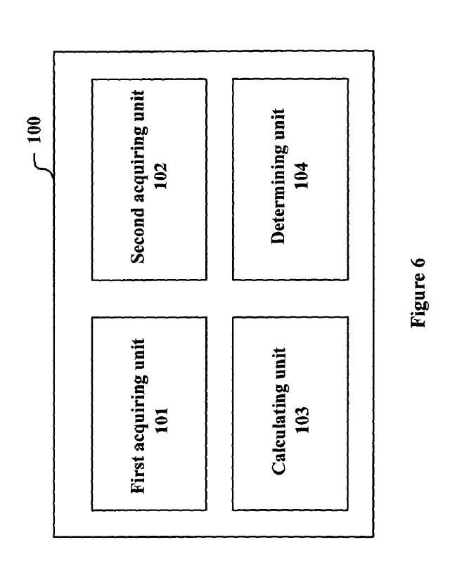
[0042] Figure 6 is a block diagram showing functional modules of an electronic
apparatus 100 for wireless communications according to an embodiment of the
present disclosure. The electronic apparatus 100 includes a first acquiring
unit 101, a
second acquiring unit 102, an interference calculating unit 103, and a
determining unit
104. The first acquiring unit 101 is configured acquire, for each candidate
resource
block, a first receiving signal measured by a respective cellular user
equipment with
respect to a pilot symbol transmitted by a base station on the candidate
resource block
in a state that a D2D communication group does not perform D2D communication.
The second acquiring unit 102 is configured to acquire a second receiving
signal
measured by the respective cellular user equipment with respect to the pilot
symbol in
a state that the D2D communication group performs D2D communication. The
- 8 -
CA 03068120 2019-12-20
interference calculation unit 103 is configured to remove an impact of the
first
receiving signal from the second receiving signal, to be used as an
interference signal
received by the cellular user equipment from a D2D emitting device in the D2D
communication group. The determining unit 104 is configured to determine a
priority
order for resource blocks available to the D2D communication group by taking
minimization of the interferences as an optimization objective. It should be
noted that
the operations of the first acquiring unit 101 and the second acquiring unit
102 do not
have a limitation in order, and an order of performing the measurement of the
first
receiving signal and the measurement of the second receiving signal is also
not
limited. In other words, the first receiving signal may be measured and
acquired first,
or the second receiving signal may be measured and acquired first. In
addition, the
first acquiring unit 101 and the second acquiring unit 102 may also be the
same
acquiring unit, and they are distinguished here only for convenience and
clarity of
description.
100431 The first acquiring unit 101, the second acquiring unit 102, the
interference
calculating unit 103 and the determining unit 104 may be implemented by, for
example, one or more processing circuitries, and the processing circuitry may
be
implemented as, for example, a chip. The electronic apparatus 100 may be, for
example, located on the BS shown in Figure 3, or communicatively connected to
the
BS. Moreover, the various components of the electronic apparatus 100 may also
be
suitably distributed at different locations of a wireless communication
network, which
is not limited herein.
100441 In order to calculate the interferences of the D2D communication group
to
the cellular user equipment using the same resource block, firstly, the first
acquiring
unit 101 and the second acquiring unit 102 respectively acquire a measurement
result
of channel measurement performed by a cellular communication device on the
candidate resource block allocated to the cellular communication device in a
case that
D2D communication is not performed and a measurement result of channel
measurement performed by the cellular communication device on the candidate
resource block allocated to the cellular communication device in a case that
D2D
communication is performed, and a difference between the two measurement
results
represents the interferences of D2D communication to the cellular user
equipment.
- 9 -
CA 03068120 2019-12-20
[0045] Specifically, in the case that the D2D communication group does not
perform the D2D communication, that is, the TUE and the RUE are in a power-on
state and are in communication with the base station while do not perform the
D2D
communication, the base station transmits a pilot symbol, for example,
transmitting
CSI estimation signaling to the cellular user equipment CUE on a corresponding
candidate resource block. Correspondingly, the CUE measures the received pilot
symbol transmitted on the corresponding candidate resource block to obtain the
first
receiving signal.
[0046] Taking a receiving signal of CUEk with respect to a pilot symbol on the
m-th
resource block RBm as an example, the first receiving signal may be expressed
as
follows:
Hm = Xm +(1)
CUEk BS ,CUE k BS ,CUE A 'CUE,,
[0047] where YrmuE, indicates the first receiving signal, that is, a signal
received by
the CUEk from the base station at a pilot position in the m-th resource block
RBm,
HCUE:k indicates a channel frequency response (CFR) between the base station
and
BS ,
the CUEk on the RBm, which may be estimated by various channel estimation
algorithms, and the estimation result is expressed by fil,cuEk = X Bms,cuEk
indicates a
pilot symbol transmitted from the base station, and NJE,, indicates additive
white
Gaussian noise (AWGN). It should be noted that in the equations herein, the
same
symbol represents the same meaning unless otherwise stated, which is not
explained
again when repeated.
[0048] Further, in the case that the D2D communication group performs D2D
communication, the base station transmits the pilot symbol, for example, the
CSI
estimation signaling, to the cellular user equipment CUE and the D2D user RUE
on
the corresponding candidate resource block. In this case, the second receiving
signal
measured by the CUE with respect to the pilot symbol may include a useful
signal
from the base station and multiplexing interferences from the TUE.
[0049] Still taking the case that the D2D communication group 1 multiplexes
the
resource block RBm of the cellular user equipment CUEk as an example, the
second
receiving signal may be expressed as follows:
- 10 -
CA 03068120 2019-12-20
.m
/ CUEk = HEmS,CLIEk = X'113:5,CUEk HTUELCUEk = XTIm lEI,CUEk + 1V CUEk (2)
[0050] where HTUin E1,CUEk indicates CFR between the TUE1 of the D2D
communication group 1 and the CUEk on the m-th resource block RBm,
XmELCUEk indicates a known pilot symbol to be transmitted to the CUEk by the
TUEI.
TU
An estimated value of HBMs,ct,Ek = XBms,cuEk may be obtained according to
equation (1),
which represents the useful signal received by the CUEk.
limE1CUEk = Xm indicates the multiplexing interferences produced due to
the
TU, TUELCUEA
D2D communication group multiplexing resources of a cellular user. N.c=muE,
indicates
AWGN.
[0051] The interference calculating unit 103 removes an impact of the first
signal
from the second receiving signal, for example, subtracting equation (1) from
equation
(2), and information of interferences of D2D communication to the cellular
user
equipment may be acquired. The above information of interferences may be
acquired
for each candidate resource block. Then, the determining unit 104 may
determine a
priority order for resource blocks available to the D2D communication group by
minimizing the interferences. For example, in the example of Figure 4, in a
case that
the D2D communication group 1 multiplexes the resource block RB2 of the CUE2,
the
above interferences are minimized, and the resource block RB2 may be
preferentially
allocated to the D2D communication group 1.
[0052] In an example, the interferences may be represented by a difference
between
a communication capacity of the cellular user equipment in the state that the
D2D
communication group does not perform D2D communication and a communication
capacity of the cellular user equipment in the state that the D2D
communication group
performs D2D communication. For example, in the state that the D2D
communication
group does not perform D2D communication, the communication capacity is
calculated based on a signal-to-noise ratio (SNR) of the cellular user
equipment on the
corresponding candidate resource block. For example, the SNR of the CUEk on
the
m-th resource block RBm may be calculated as follows:
- 11 -
CA 03068120 2019-12-20
fIBS,CUEk 17;S,CUEk 1 2
M
SNYn cuEk = ________________________________
2 (3)
am,cuE,
[0053] Where HBS Xs,cuE, 2
,CUE, = Indicates a power of the useful signal received
'en =
by the CUEk, cr2.,cuE, indicates a power of/q,Ek . The capacity of the CUEk on
the
m-th resource block RBm may be expressed as follows:
CcinuE, = W log2(1 + SNK.nuE, ) (4)
where W represents a bandwidth of the RB.
[0054] In the state that the D2D communication group performs D2D
communication, there are interferences of D2D communication to the cellular
user
equipment, and the communication capacity may be calculated based on the
signal to
interference and noise ratio (SINR) of the cellular user equipment on the
corresponding candidate resource block. For example, the SINR of the CUEk on
the
m-th resource block RBm may be calculated as follows:
e m s,cuEk ' XBins,cuEk 2
SiNknuEk = 2 (5)
2 ,
-1/77UE I, CUEk = XEI,CUEk a m,cuEk
[0055] where o-'2.,cuE9 indicates a power of N' Cm UEk . Accordingly, the
capacity of the
CUEk on the m-th resource block RBm may be calculated as follows:
CUE, = W log2 (1 + S/NR'cnuEk ) (6)
[0056] Therefore, a difference between a capacity of the cellular user
equipment
CUEk in the state that the D2D communication is not performed and a capacity
of the
cellular user equipment CUEk in the state that the D2D communication is
performed
.. is expressed as follows:
DCcmuEk =CcmuEk ¨CcuEk (7)
[0057] The determining unit 104 may rank the resource blocks according to the
above mentioned capacity difference for each resource block, so that a
resource block
producing the minimum interferences to the cellular user equipment, that is, a
resource block with the smallest capacity difference is ranked foremost, and
the D2D
- 12 -
CA 03068120 2019-12-20
communication group is preferentially allocated with the resource block that
is ranked
foremost. For example, if the D2D communication group requires two resource
blocks, two resource blocks with the smallest capacity difference may be
allocated to
the D2D communication group, and so on.
.. [0058] Further, in the case of allocating resources to multiple D2D
communication
groups, a difference in communication capacity shown in equation (7) may be
calculated for each of the D2D communication groups, and the determining unit
104
is configured to rank, for each of the D2D communication groups, its available
resource blocks according to differences in communication capacity. In a case
that the
same available resource block is to be allocated to two or more D2D
communication
groups, the resource block is preferentially allocated to the D2D
communication
group with the smallest capacity difference.
[0059] As described above, although the state that D2D communication is not
performed is described first and the state that D2D communication is performed
is
described later, this is not limited, and measurement in the state that the
D2D
communication is performed may be performed first, and then the measurement in
the
state that the D2D communication is not performed may be performed.
[0060] In an example, the state that the D2D communication is performed is a
state
that temporary D2D communication is performed. For example, as shown in Figure
7,
the electronic apparatus 100 may further include a control unit 105 configured
to
control the base station to transmit temporary D2D communication signaling, to
instruct the D2D emitting device to transmit the pilot symbol on a
corresponding pilot
location of the candidate resource block.
[0061] The control unit 105 may instruct multiple D2D emitting devices to
transmit
pilot symbols on the candidate resource block in a multiplexing manner. Figure
8
shows a multiplexing manner. In the example shown in Figure 8, the TUE1
transmits
a pilot symbol on the seventh subcarrier of a first OFDM symbol on the m-th
resource
block, and the TUE2 transmits a pilot symbol on the first subcarrier of a
first OFDM
symbol on the resource block, and so on. It can be seen that in the example of
the
resource block shown in Figure 8, one resource block may be multiplexed by up
to
eight TUEs. If the number of TUEs multiplex is more than eight, for example,
the
TUEs may transmit the pilot symbol in a time division manner.
- 13 -
CA 03068120 2019-12-20
[0062] Although not shown in Figures 6 and 7, the electronic apparatus 100 may
further include a transceiving unit, for example, configured to transmit the
pilot
symbol to the cellular user equipment and D2D receiving device, and receive a
first
receiving signal and a second receiving signal from the cellular user
equipment. The
transceiving unit may further be configured to transmit a temporary D2D
communication instruction to a D2D emitting device. The transceiving unit may
be
implemented, for example, as an antenna and related circuit elements, which
may be
implemented, for example, as a chip.
[0063] In the above, an example of resource block allocation by taking
minimization of the interferences to the cellular user equipment is described
as an
optimization objective, but the optimization objective is not limited thereto,
for
example, maximization of the D2D communication capacity together with
minimization of the interferences the cellular user equipment being subjected
to may
also be taken as the optimization objective.
[0064] In such an example, the first acquiring unit 101 is further configured
to
acquire a third receiving signal measured by a D2D receiving device of the D2D
communication group with respect to a pilot symbol transmitted by the base
station on
the corresponding candidate resource block in the state that the D2D
communication
group does not perform D2D communication, for example, as an interference
signal
of interferences of the base station to the D2D receiving device. The second
acquiring
unit 102 is further configured to acquire a fourth receiving signal measured
by the
D2D receiving device with respect to the pilot symbol in the state that the
D2D
communication group performs D2D communication. The calculating unit 103 is
configured to remove an impact of the third receiving signal from the fourth
receiving
signal, to be used as an expected signal received by the D2D receiving device
from
the D2D emitting device. The determining unit 104 is configured to consider,
while
determining the a priority order for the resource blocks available to the D2D
communication group by taking minimization of the interferences as the
optimization
objective, maximization of communication capacity of the D2D communication
group.
[0065] For example, in the state that the D2D communication group does not
perform D2D communication, the base station transmits the pilot symbol to the
RUE
- 14 -
CA 03068120 2019-12-20
of the D2D communication group and a corresponding CUE on the respective
candidate resource blocks, and the RUE measures the received pilot symbol to
obtain
the third receiving signal. Note that the TUE is not involved in the
measurement.
Since the D2D communication group does not perform D2D communication, the
third
receiving signal measured by the RUE represents the interferences the downlink
transmission of the cellular user equipment will produce to the D2D
communication,
in a case that the D2D communication multiplexes the resource block of the
corresponding cellular user equipment. Taking a receiving signal of RUE1 with
respect to the pilot symbol on the m-th resource block RBm as an example, the
third
receiving signal may be expressed as follows:
=1-1" = X' + Nm (8)
RUE1 BS,RUE) BS,RUE1 RUE'
[0066] where 17,1E, represents the third receiving signal, that is, a signal
received by
the RUE1 from the base station on a pilot location in the resource block RBm,
HRuE, represents a CFR between the base station and the RUE] on the RBm, which
may be estimated by various channel estimation algorithms, where an estimation
result is expressed by ) BrnS,RUEi = X Bms,RuEl represents a pilot symbol
transmitted from
the base station, and \ ,E represents AWGN.
[0067] In the state that the D2D communication group performs D2D
communication, for example, the TUE transmits a pilot symbol to the RUE at a
corresponding pilot location in the candidate resource block. In addition to
the useful
signal (a signal which corresponds to the pilot symbol) from the TUE, the
fourth
receiving signal received by the RUE further includes downlink multiplexing
interferences caused by the BS to the RUE when the BS transmits the pilot
symbol to
the cellular user equipment. Still taking the receiving signal of the RUE1
with respect
to the pilot symbol on the m-th resource block RBm as an example, the fourth
receiving signal may be expressed as follows:
õ.. rn
I RUE)
= I BmS,RUE1 ,RUE1 HTU rn m El,RUE! X TmUELRUE) + v
RUE1 (9)
[0068] where HTmm,RuEi represents a CFR between the TUE1 and the RUE1 on the
- 15 -
CA 03068120 2019-12-20
resource block RBm , X TumEl,RUEI represents a pilot symbol to be sent by the
TUE1 to
the RUE1, and correspondingly, H Bms,RuEi = X Bms,RuEl may be estimated
according to the
equation (8), which represents interferences caused by downlink transmission
between the BS and the CUEk. For RUE1, H
TmUELRUE1 = X TmUEI,RUE1 is the useful signal,
and AT'RmuE, is AWGN.
[0069] For example, the communication capacity of the D2D communication group
may be calculated based on a signal to interference and noise ratio of the D2D
receiving device on the corresponding candidate resource block. Still taking
the RUE]
multiplexing the resource block RBm of CUEk as an example, the SINR of the
RUE1
on the m-th resource block RBm is expressed by the following equation (10):
2
Iftm EI,RUE1 = XTmlIELRUE1
SINK" = rU (10)
RUE)
+ 0:2 m,RUE1
-11731S,RUEI = Xi; ,RUE112
[0070] where HTinUELRUE, represents an estimated value of HTinUELRUEi
.2
m,RUEirepresents a power of N RUE, . Correspondingly, the capacity of the RUE1
on
the m-th resource block RBm may be calculated as follows:
CRtmUE, = W log2(1 + S/NRZE, ) (11)
[0071] For example, the determining unit 104 may rank the candidate resource
blocks according to the follows:
_RUCEI CUEk
Dm = _____________________________________ (12)
cuEk
[0072] Here, the denominator of the equation (12) represents the capacity
difference
of the CUEk as shown by the above equation (7). It may be understood that a
larger Dm represents a larger capacity of D2D communication on the resource
block
RBm and smaller interferences to the corresponding cellular user equipment.
Therefore, the resource block RBm may be preferentially allocated to the D2D
communication group. Similarly, if the D2D communication group requires two
resource blocks, two resource blocks with the largest 1:Y" may be allocated to
the
- 16 -
CA 03068120 2019-12-20
D2D communication group, and so on.
[0073] In a case that there are multiple RUEs in the D2D communication group,
for
the D2D communication group, multiple third receiving signals and multiple
fourth
receiving signals may be acquired for each candidate resource block, such that
the
SINR of each of multiple RUEs may be obtained according to equation (10), and
communication capacity of each of multiple RUEs may be obtained according to
equation (11). In this case, the candidate resource blocks may be ranked based
on a
sum of communication capacities of the multiple RUEs or a mean value of the
communication capacities.
[0074] Further, in the case of allocating resources to multiple D2D
communication
groups, the indicator Dm shown in equation (12) may be calculated for each of
the
D2D communication groups, and the determining unit 104 is configured to rank,
for
each of the D2D communication groups, its available resource blocks according
to the
corresponding indicator. In a case that the same available resource block is
to be
allocated to two or more D2D communication groups, the resource block is
preferentially allocated to a D2D communication group having the largest
indicator Dm.
[0075] In this example, the transceiving unit may be further configured to
receive
the third receiving signal and the fourth receiving signal from the D2D
receiving
device.
[0076] Similarly, although the state that D2D communication is not performed
is
described first and the state that D2D communication is performed is described
later,
this is not limited, and measurement in the state that D2D communication is
performed may be performed first, and then the measurement in the state that
D2D
communication is performed may be performed later.
[0077] In the above description, the operations of the first acquiring unit
101, the
second acquiring unit 102, the calculating unit 103, the determining unit 104,
and the
control unit 105 are performed for each of the candidate resource blocks. In
other
examples, the candidate resource blocks may be determined by pre-selection to
further improve the efficiency of resource allocation. For example, a resource
block of
a CUE that may produce less multiplexing interferences to D2D communication
may
-17-
CA 03068120 2019-12-20
be determined as a candidate resource block by pre-selection.
[0078] For example, the determining unit 104 may determine the candidate
resource
block in the following way: calculating a difference between downlink
transmitting
power of each cellular user equipment in a cell and downlink transmitting
power of
the D2D emitting device; and determining a resource block corresponding to a
cellular user equipment for which the difference is larger than a
predetermined
threshold as the candidate resource block for the D2D communication.
[0079] Specifically, for each D2D communication group, downlink transmitting
power of the cellular user equipment is compared with the downlink
transmitting
power of the D2D emitting device. If a difference between the two downlink
transmitting powers is greater than a predetermined threshold, it means that a
location
of the cellular user equipment may be far apart from a location of the D2D
receiving
device, so that multiplexing interferences caused when the D2D communication
group multiplexes the resource block of the cellular user equipment would be
small.
Therefore, the resource block corresponding to the cellular user equipment may
be
determined as the candidate resource block for D2D communication. Note that
the
difference between the downlink transmitting power of the cellular user
equipment
and the downlink transmitting power of the D2D emitting device described
herein
may refer to an absolute value of a difference obtained by performing
subtraction
therebetween.
[0080] In this way, the candidate resource block is determined for each D2D
communication group. It should be understood that for different D2D
communication
groups, the determined cellular user equipment that meet the above condition
may be
different, and therefore, the candidate resource blocks may also be different.
A
candidate resource block determined for one D2D communication group is
referred to
as a resource link table of the D2D communication group hereinafter.
[0081] Taking the scenario shown in Figure 4 as an example, the cellular user
equipment for which the calculated difference between transmitting powers is
less
than the predetermined threshold is as shown within a dashed line circle.
There are
CUE1 and CUE4 in the circle of RUEI. Compared with the CUE] and the CUE4,
CUE2, CUE3 and CUE5 are farther away from the RUE'. If TUE1 and the RUE'
perform D2D communication using resource blocks occupied by the CUE2, the CUE3
-18-
CA 03068120 2019-12-20
and the CUE5, the multiplexing interferences thus caused may be smaller than
the
multiplexing interferences caused by multiplexing the resource blocks occupied
by
the CUE1 and the CUE4.
[0082] If the resource blocks occupied by the CUE2, the CUE3, and the CUE5 are
determined as candidate resource blocks, the above operations of measurement,
calculation, and ranking are performed only for these candidate resource
blocks. In an
example, a resource link table as shown in Figures 9 and 10 may be
established,
where Figure 9 shows a resource link table established for the D2D
communication
group 1, and Figure 10 shows a resource link table established for the D2D
communication group 2. According to Figure 9, the operations such as
measurement
are performed on the resource blocks RBI, RB2, and RB7 occupied by the CUE2,
the
resource blocks RB3, RB4, and RB5 occupied by the CUE3, and the resource block
RBI occupied by the CUE5. Similarly, according to Figure 10, the operations
such as
measurement are performed on the resource blocks RBI, RB2, and RB7 occupied by
the CUE2, the resource block RB6 occupied by the CUEa, and the resource block
RBio
occupied by the CUE5, each operation is described in detail in the above, and
is not
repeated herein.
[0083] It can be seen that the candidate resource block is determined by
filtering the
resource blocks, such that the number of resource blocks to be measured and
calculated can be effectively reduced, thereby alleviating signaling and
computational
load, thus improving the allocation efficiency of resource blocks.
[0084] For ease of understanding, Figure 11 is a schematic diagram showing an
information procedure among a BS, a cellular mobile device, and a D2D device.
However, it should be understood that this information procedure is only an
example
and is not limitative.
[0085] First, the BS transmits a CSI estimation message to the RUE and the CUE
to
measure channel status information. The CSI estimation message includes a
pilot
symbol transmitted at a pilot location on a candidate resource block, and the
RUE and
the CUE measure the pilot symbol on the corresponding candidate resource
block,
and report the measurement result, for example, the first receiving signal and
the
second receiving signal, to the BS.
- 19 -
CA 03068120 2019-12-20
[0086] Subsequently, the BS transmits a temporary D2D communication
instruction
to the TUE to instruct the D2D communication group to perform temporary D2D
communication. For example, the temporary D2D communication is that the TUE
transmits the pilot symbol on the corresponding candidate resource block to
the RUE.
In this case, the BS transmits the CSI estimation message to the RUE and the
CUE
again, and the RUE and the CUE measure the received signal again in the
presence of
the temporary D2D communication and report the measurement result to the BS.
[0087] After receiving the measurement result, the BS calculates an
optimization
indicator in combination with the measurement result obtained when the
temporary
D2D communication is not performed. For example, the BS calculates the
capacity
difference of the CUE, the communication capacity of the D2D communication
group
for performing D2D communication, and the like.
[0088] The BS ranks the candidate resource blocks based on the calculated
optimization indicator, and preferentially allocates a resource block ranked
foremost
for D2D. In this way, the allocation optimization of the available resource
blocks to
D2D communication can be realized, the interferences to the cellular user
equipment
can be reduced, and/or the D2D communication capacity can be improved, thereby
improving the system performance. Furthermore, the information procedure of
Figure
11 may also be modified such that the measurement in the state that the
temporary
D2D communication is performed can be performed first, that is, the process
within
the rectangular block of Figure 11 may be performed before the first "CSI
estimation
message".
[0089] Although not shown in Figure 11, a process of establishing a resource
link
table may be performed before the information procedure, so that the procedure
shown in Figure 11 is performed only for the candidate resource blocks in the
resource link table, thereby further improving the efficiency of resource
block
allocation for D2D communication.
[0090] In summary, an electronic apparatus is provided in the present
embodiment.
With this electronic apparatus, interferences of D2D communication to the
cellular
user equipment may be acquired by determining a difference between a receiving
signal of the cellular user equipment with respect to a pilot symbol in the
state that
D2D communication is not performed and a receiving signal of the cellular user
- 20 -
CA 03068120 2019-12-20
equipment with respect to the pilot symbol in the state that D2D communication
is
performed, such that the resource allocation for D2D communication can be
optimized based on the interferences, thereby improving utilization efficiency
of
transmission resources. In addition, the electronic apparatus may also obtain
the
communication capacity of the D2D device by using the difference between the
receiving signal of the D2D receiving device in the state that the D2D
communication
is not performed and the receiving signal of the D2D receiving device in the
state that
the D2D communication is performed, such that the resource allocation for D2D
communication may be optimized based on the communication capacity and the
above mentioned interferences, thereby improving the utilization efficiency of
transmission resources.
<Second Embodiment>
[0091] Figure 12 is a block diagram showing functional modules of an
electronic
apparatus 200 for wireless communications according to another embodiment of
the
present disclosure. The electronic apparatus 200 includes a receiving unit 201
and a
transmitting unit 202. The receiving unit 201 is configured to receive an
instruction to
perform temporary D2D communication from a base station. The transmitting unit
202 is configured to transmit a pilot symbol on the candidate resource block.
[0092] For example, the receiving unit 201 and the transmitting unit 202 may
be
implemented by an antenna and related circuit elements, which may be
implemented,
for example, as a chip. The electronic apparatus 200 may be located at a side
of a
terminal device or communicatively connected to the terminal device, but the
present
disclosure is not limited thereto. The electronic apparatus 200 may be located
at a side
of any communication device that may perform D2D communication or
communicatively connected to such a communication device.
[0093] The instruction to perform temporary D2D communication includes, for
example, instructing the D2D device to transmit a pilot symbol on a
corresponding
pilot location of the candidate resource block. The pilot location is as shown
in Figure
5, for example.
[0094] In an example, the transmitting unit 202 is configured to transmit the
pilot
-21-
CA 03068120 2019-12-20
symbol on the candidate resource block in a manner of multiplexing with a
transmitting unit of other electronic apparatus. The multiplexing manner is as
shown
in Figure 8, for example.
[0095] The electronic apparatus 200 according to the present embodiment can
perform temporary D2D communication to transmit the pilot symbol on the
candidate
resource block.
<Third Embodiment>
[0096] In the process of describing the electronic apparatus for wireless
communications in the embodiments described above, obviously, some processing
and methods are also disclosed. Hereinafter, an overview of the methods is
given
without repeating some details disclosed above. However, it should be noted
that,
although the methods are disclosed in a process of describing the electronic
apparatus
for wireless communications, the methods do not certainly employ or are not
certainly
executed by the aforementioned components. For example, the embodiments of the
electronic apparatus for wireless communications may be partially or
completely
implemented with hardware and/or firmware, the method described below may be
executed by a computer-executable program completely, although the hardware
and/or firmware of the electronic apparatus for wireless communications can
also be
used in the methods.
[0097] Figure 13 is a flowchart showing a method for wireless communications
according to an embodiment of the present disclosure. As shown in Figure 13,
the
method includes: for each candidate resource block, acquiring a first
receiving signal
measured by a respective cellular user equipment with respect to a pilot
symbol
transmitted by a base station on the candidate resource block in a state that
a D2D
communication group does not perform D2D communication, and a second receiving
signal measured by the respective cellular user equipment with respect to the
pilot
symbol in a state that the D2D communication group performs D2D communication,
respectively (S11); removing an impact of the first receiving signal from the
second
receiving signal, to be used as an interference signal received by the
cellular user
equipment from a D2D emitting device in the D2D communication group (S12); and
- 22 -
CA 03068120 2019-12-20
determining a priority order for resource blocks available to the D2D
communication
group by taking minimization of the interferences as an optimization objective
(S15).
[0098] For example, in step S15, the interferences may be represented by a
difference between the communication capacity of the cellular user equipment
in the
.. state that the D2D communication group does not perform D2D communication
and
the communication capacity of the cellular user equipment in the state that
the D2D
communication group performs D2D communication. In an example, the
communication capacity of the cellular user equipment in the state that the
D2D
communication group does not perform D2D communication is calculated based on
a
signal to noise ratio of the cellular user equipment on the corresponding
candidate
resource block, and the communication capacity of the cellular user equipment
in the
state that the D2D communication group performs D2D communication is
calculated
based on a signal to interference and noise ratio of the cellular user
equipment on the
corresponding candidate resource block.
.. [0099] In step S11, the state that the D2D communication is performed may
be a
state that temporary D2D communication is performed. This may be implemented
by
controlling the base station to transmit temporary D2D communication
signaling, to
instruct the D2D emitting device to transmit the pilot symbol at a
corresponding pilot
location on the candidate resource block. In an example, instructing the D2D
emitting
.. device to transmit the pilot symbol at the corresponding pilot location on
the
candidate resource block may include: instructing multiple D2D emitting
devices to
transmit the pilot symbol on the candidate resource block in a multiplexing
manner.
[0100] In addition, as shown by the dashed line block in Figure 13, the above
method may further include the following steps: for each candidate resource
block,
acquiring a third receiving signal measured by a D2D receiving device of the
D2D
communication group with respect to a pilot symbol transmitted by the base
station on
the candidate resource block in the state that the D2D communication group
does not
perform D2D communication, and a fourth receiving signal measured by the D2D
receiving device with respect to the pilot symbol in the state that the D2D
communication group performs D2D communication, respectively (S13); and
removing an impact of the third receiving signal from the fourth receiving
signal, to
be used as an expected signal received by the D2D receiving device from the
D2D
- 23 -
CA 03068120 2019-12-20
emitting device (S14). While determining the priority order for the resource
blocks
available to the D2D communication group by taking minimization of the
interferences as the optimization objective in step S15, maximization of
communication capacity of the D2D communication group is also considered.
101011 For example, the communication capacity of the D2D communication group
may be calculated based on a signal to interference and noise ratio of the D2D
receiving device on the corresponding candidate resource block.
[0102] The above method is performed for each candidate resource block, and in
some examples, the candidate resource block is determined by pre-selection.
For
example, the candidate resource block may be determined in the following way:
calculating a difference between downlink transmitting power of each cellular
user
equipment in a cell and downlink transmitting power of the D2D emitting
device; and
determining a resource block corresponding to a cellular user equipment for
which the
difference is larger than a predetermined threshold as a candidate resource
block for
D2D communication.
[0103] Figure 14 is a flowchart showing a method for wireless communications
according to another embodiment of the present disclosure. The method
includes:
receiving, from a base station, an instruction to perform temporary D2D
communication (S21); and transmitting a pilot symbol on a candidate resource
block
(S22).
[0104] For example, in step S22, the pilot symbol may be transmitted on the
candidate resource block in a manner of multiplexing with other electronic
apparatus.
[0105] It should be noted that the above methods may be used in combination
with
each other or separately, and the details thereof have been described in
detail in the
first to second embodiments, which are not repeated herein.
[0106] The technology of the present disclosure is applicable to various
products.
For example, the electronic apparatus 100 may be applied at a side of a base
station,
and the electronic apparatus 200 may be applied at a side of a terminal
device. The
base station may be realized as any type of evolved Node B (eNB) such as a
macro
eNB and a small eNB. The small eNB such as a pico eNB, micro eNB and a home
- 24 -
CA 03068120 2019-12-20
(femto-cell) eNB may have a smaller coverage range than a macro cell.
Alternatively,
the base station may also be implemented as any other type of base stations,
such as a
NodeB and a base transceiver station (BTS). The base station may include a
body
(also referred to as a base station device) configured to control wireless
communications; and one or more remote radio heads (RRHs) arranged in a
different
position from the body. In addition, various types of user equipments may each
operate as the base station by temporarily or semi-persistently executing a
base station
function.
[0107] For example, the terminal device may be realized as a mobile terminal
(such
as a smartphone, a tablet personal computer (PC), a notebook PC, a portable
game
terminal, a portable/dongle type mobile router, and a digital camera), or an
in-vehicle
terminal (such as a car navigation device). The terminal device may also be
realized
as a terminal (which is also referred to as a machine type communication (MTC)
terminal) that performs machine-to-machine (M2M) communication. Furthermore,
the terminal device may be a wireless communication module (such as an
integrated
circuit module including a single die) mounted on each of the terminals.
[0108] Application examples of the base station and the terminal device are
described hereinafter, however, it should be understood that these application
examples are non-restrictive.
[Application examples regarding the base station]
(First application example)
[0109] Figure 15 is a block diagram illustrating a first example of a
schematic
configuration of an eNB to which the technology of the present disclosure may
be
applied. An eNB 800 includes one or more antennas 810 and a base station
apparatus
820. The base station apparatus 820 and each of the antennas 810 may be
connected
to each other via a radio frequency (RF) cable. Each of the antennas 810
includes a
single or multiple antenna elements (such as multiple antenna elements
included in a
multiple-input multiple-output (MIMO) antenna), and is used for the base
station
apparatus 820 to transmit and receive wireless signals. As shown in Figure 15,
the
eNB 800 may include the multiple antennas 810. For example, the multiple
antennas
- 25 -
CA 03068120 2019-12-20
810 may be compatible with multiple frequency bands used by the eNB 800.
Although Figure 15 shows the example in which the eNB 800 includes the
multiple
antennas 810, the eNB 800 may also include a single antenna 810.
[0110] The base station apparatus 820 includes a controller 821, a memory 822,
a
network interface 823, and a radio communication interface 825.
[0111] The controller 821 may be, for example, a CPU or a DSP, and operates
various functions of a higher layer of the base station apparatus 820. For
example, the
controller 821 generates a data packet from data in signals processed by the
radio
communication interface 825, and transfers the generated packet via the
network
interface 823. The controller 821 may bundle data from multiple base band
processors
to generate the bundled packet, and transfer the generated bundled packet. The
controller 821 may have logical functions of performing control such as radio
resource control, radio bearer control, mobility management, admission control
and
scheduling. The control may be performed in corporation with an eNB or a core
network node in the vicinity. The memory 822 includes a RAM and a ROM, and
stores a program executed by the controller 821 and various types of control
data
(such as terminal list, transmission power data and scheduling data).
[0112] The network interface 823 is a communication interface for connecting
the
base station apparatus 820 to a core network 824. The controller 821 may
communicate with a core network node or another eNB via the network interface
823.
In this case, the eNB 800, and the core network node or another eNB may be
connected to each other via a logic interface (such as an Si interface and an
X2
interface). The network interface 823 may also be a wired communication
interface or
a wireless communication interface for wireless backhaul. If the network
interface
823 is a wireless communication interface, the network interface 823 may use a
higher frequency band for wireless communication than that used by the radio
communication interface 825.
[0113] The radio communication interface 825 supports any cellular
communication scheme (such as Long Term Evolution (LTE) and LTE-advanced), and
provides wireless connection to a terminal located in a cell of the eNB 800
via the
antenna 810. The radio communication interface 825 may typically include, for
example, a baseband (BB) processor 826 and an RF circuit 827. The BB processor
- 26 -
CA 03068120 2019-12-20
826 may perform, for example, encoding/decoding, modulating/demodulating, and
multiplexing/demultiplexing, and performs various types of signal processing
of
layers (such as L 1, Media Access Control (MAC), Radio Link Control (RLC), and
a
Packet Data Convergence Protocol (PDCP)). The BB processor 826 may have a part
or all of the above-described logical functions instead of the controller 821.
The BB
processor 826 may be a memory storing communication control programs, or a
module including a processor and a related circuit configured to execute the
programs. Updating the program may allow the functions of the BB processor 826
to
be changed. The module may be a card or a blade that is inserted into a slot
of the
base station apparatus 820. Alternatively, the module may also be a chip that
is
mounted on the card or the blade. Meanwhile, the RF circuit 827 may include,
for
example, a mixer, a filter, and an amplifier, and transmits and receives
wireless
signals via the antenna 810.
[0114] As show in Figure 15, the radio communication interface 825 may include
the multiple BB processors 826. For example, the multiple BB processors 826
may be
compatible with multiple frequency bands used by the eNB 800. The radio
communication interface 825 may include multiple RF circuits 827, as shown in
Figure 15. For example, the multiple RF circuits 827 may be compatible with
multiple
antenna elements. Although Figure 15 shows the example in which the radio
communication interface 825 includes the multiple BB processors 826 and the
multiple RF circuits 827, the radio communication interface 825 may also
include a
single BB processor 826 or a single RF circuit 827.
(Second application example)
[0115] Figure 16 is a block diagram illustrating a second example of a
schematic
configuration of an eNB to which the technology of the present disclosure may
be
applied. An eNB 830 includes one or more antennas 840, a base station
apparatus 850,
and an RRH 860. The RRH 860 and each of the antennas 840 may be connected to
each other via an RF cable. The base station apparatus 850 and the RRH 860 may
be
connected to each other via a high speed line such as an optical fiber cable.
[0116] Each of the antennas 840 includes a single or multiple antennal
elements
- 27 -
CA 03068120 2019-12-20
(such as multiple antenna elements included in an MIMO antenna), and is used
for the
RRH 860 to transmit and receive wireless signals. As shown in Figure 16, the
eNB
830 may include the multiple antennas 840. For example, the multiple antennas
840
may be compatible with multiple frequency bands used by the eNB 830. Although
Figure 16 shows the example in which the eNB 830 includes the multiple
antennas
840, the eNB 830 may also include a single antenna 840.
[0117] The base station apparatus 850 includes a controller 851, a memory 852,
a
network interface 853, a radio communication interface 855, and a connection
interface 857. The controller 851, the memory 852, and the network interface
853 are
the same as the controller 821, the memory 822, and the network interface 823
described with reference to Figure 15.
[0118] The radio communication interface 855 supports any cellular
communication scheme (such as LTE and LTE-advanced), and provides wireless
communication to a terminal located in a sector corresponding to the RRH 860
via the
RRH 860 and the antenna 840. The radio communication interface 855 may
typically
include, for example, a BB processor 856. The BB processor 856 is the same as
the
BB processor 826 described with reference to Figure 15, except that the BB
processor
856 is connected to an RF circuit 864 of the RRH 860 via the connection
interface
857. As show in Figure 16, the radio communication interface 855 may include
the
multiple BB processors 856. For example, the multiple BB processors 856 may be
compatible with multiple frequency bands used by the eNB 830. Although Figure
16
shows the example in which the radio communication interface 855 includes the
multiple BB processors 856, the radio communication interface 855 may also
include
a single BB processor 856.
[0119] The connection interface 857 is an interface for connecting the base
station
apparatus 850 (radio communication interface 855) to the RRH 860. The
connection
interface 857 may also be a communication module for communication in the
above-described high speed line that connects the base station apparatus 850
(radio
communication interface 855) to the RRH 860.
[0120] The RRH 860 includes a connection interface 861 and a radio
communication interface 863.
-28-
CA 03068120 2019-12-20
[0121] The connection interface 861 is an interface for connecting the RRH 860
(radio communication interface 863) to the base station apparatus 850. The
connection interface 861 may also be a communication module for communication
in
the above-described high speed line.
[0122] The radio communication interface 863 transmits and receives wireless
signals via the antenna 840. The radio communication interface 863 may
typically
include, for example, the RF circuit 864. The RF circuit 864 may include, for
example, a mixer, a filter and an amplifier, and transmits and receives
wireless signals
via the antenna 840. The radio communication interface 863 may include
multiple RF
circuits 864, as shown in Figure 16. For example, the multiple RF circuits 864
may
support multiple antenna elements. Although Figure 16 shows the example in
which
the radio communication interface 863 includes the multiple RF circuits 864,
the radio
communication interface 863 may also include a single RF circuit 864.
[0123] In the eNB 800 shown in Figure 15 and the eNB 830 shown in Figure 16,
the functions of the transceiver unit described in the first embodiment may be
implemented by the radio communication interface 825 and the radio
communication
interface 855 and/or the radio communication interface 863. At least a part of
the
functions may be implemented by a controller 821 and a controller 851. The
first
acquiring unit 101, the second acquiring unit 102, the calculating unit 103,
the
determining unit 104 and the control unit 105 described with reference to
Figures 6
and 7 may be implemented by the controller 821 and the controller 851. For
example,
the controller 821 and the controller 851 may rank the candidate resource
blocks by
performing the functions of the first acquiring unit 101, the second acquiring
unit 102,
the calculating unit 103, and the determining unit 104, and control the base
station to
transmit the Temporary D2D communication instruction by performing the
function
of the control unit 105.
[Application example regarding the terminal device]
(First Application Example)
[0124] Figure 17 is a block diagram illustrating an example of a schematic
configuration of a smartphone 900 to which the technology of the present
disclosure
- 29 -
CA 03068120 2019-12-20
may be applied. The smart phone 900 includes a processor 901, a memory 902, a
storage 903, an external connection interface 904, a camera 906, a sensor 907,
a
microphone 908, an input device 909, a display device 910, a speaker 911, a
radio
communication interface 912, one or more antenna switches 915, one or more
antennas 916, a bus 917, a battery 918, and an auxiliary controller 919.
[0125] The processor 901 may be, for example, a CPU or a system on a chip
(SoC),
and controls functions of an application layer and another layer of the smart
phone
900. The memory 902 includes a RAM and a ROM, and stores a program executed by
the processor 901 and data. The storage 903 may include a storage medium such
as a
semiconductor memory and a hard disk. The external connection interface 904 is
an
interface for connecting an external device (such as a memory card and a
universal
serial bus (USB) device) to the smart phone 900.
[0126] The camera 906 includes an image sensor (such as a charge coupled
device
(CCD) and a complementary metal oxide semiconductor (CMOS)), and generates a
captured image. The sensor 907 may include a group of sensors, such as a
measurement sensor, a gyro sensor, a geomagnetism sensor, and an acceleration
sensor. The microphone 908 converts sounds that are inputted to the smart
phone 900
to audio signals. The input device 909 includes, for example, a touch sensor
configured to detect touch onto a screen of the display device 910, a keypad,
a
keyboard, a button, or a switch, and receives an operation or an information
inputted
from a user. The display device 910 includes a screen (such as a liquid
crystal display
(LCD) and an organic light-emitting diode (OLED) display), and displays an
output
image of the smart phone 900. The speaker 911 converts audio signals that are
outputted from the smart phone 900 to sounds.
[0127] The radio communication interface 912 supports any cellular
communication scheme (such as LTE and LTE-advanced), and performs a wireless
communication. The radio communication interface 912 may include, for example,
a
BB processor 913 and an RF circuit 914. The BB processor 913 may perform, for
example, encoding/decoding, modulating/demodulating, and
multiplexing/de-multiplexing, and perform various types of signal processing
for
wireless communication. The RF circuit 914 may include, for example, a mixer,
a
filter and an amplifier, and transmits and receives wireless signals via the
antenna 916.
-30-
CA 03068120 2019-12-20
It should be noted that although Figure 17 shows a case where one RF link is
connected to one antenna, which is only illustrative and a case where one RF
link is
connected to multiple antennas through multiple phase shifters may exist. The
radio
communication interface 912 may be a chip module having the BB processor 913
and
the RF circuit 914 integrated thereon. The radio communication interface 912
may
include multiple BB processors 913 and multiple RF circuits 914, as shown in
Figure
17. Although Figure 17 shows the example in which the radio communication
interface 912 includes the multiple BB processors 913 and the multiple RF
circuits
914, the radio communication interface 912 may also include a single BB
processor
913 or a single RF circuit 914.
[0128] Furthermore, in addition to a cellular communication scheme, the radio
communication interface 912 may support another type of wireless communication
scheme such as a short-distance wireless communication scheme, a near field
communication scheme, and a radio local area network (LAN) scheme. In this
case,
the radio communication interface 912 may include the BB processor 913 and the
RF
circuit 914 for each wireless communication scheme.
[0129] Each of the antenna switches 915 switches connection destinations of
the
antennas 916 among multiple circuits (such as circuits for different wireless
communication schemes) included in the radio communication interface 912.
[0130] Each of the antennas 916 includes a single or multiple antenna elements
(such as multiple antenna elements included in an MIMO antenna) and is used
for the
radio communication interface 912 to transmit and receive wireless signals.
The smart
phone 900 may include the multiple antennas 916, as shown in Figure 17.
Although
Figure 17 shows the example in which the smart phone 900 includes the multiple
antennas 916, the smart phone 900 may also include a single antenna 916.
[0131] Furthermore, the smart phone 900 may include the antenna 916 for each
wireless communication scheme. In this case, the antenna switches 915 may be
omitted from the configuration of the smart phone 900.
[0132] The bus 917 connects the processor 901, the memory 902, the storage
903,
the external connection interface 904, the camera 906, the sensor 907, the
microphone
908, the input device 909, the display device 910, the speaker 911, the radio
-31-
CA 03068120 2019-12-20
communication interface 912, and the auxiliary controller 919 to each other.
The
battery 918 supplies power to blocks of the smart phone 900 shown in Figure 17
via
feeder lines that are partially shown as dashed lines in Figure 17. The
auxiliary
controller 919, operates a minimum necessary function of the smart phone 900,
for
example, in a sleep mode.
[0133] In the smartphone 900 shown in Figure 17, the receiving unit 201 and
the
transmitting unit 202 described in the second embodiment may be implemented by
the
radio communication interface 912. At least a part of the functions of the
receiving
unit 201 and the transmitting unit 202 may be implemented by the processor 901
and
the auxiliary controller 919.
(Second application example)
[0134] Figure 18 is a block diagram illustrating an example of a schematic
configuration of a car navigation apparatus 920 to which the technology of the
present
disclosure may be applied. The car navigation apparatus 920 includes a
processor 921, =
a memory 922, a global positioning system (GPS) module 924, a sensor 925, a
data
interface 926, a content player 927, a storage medium interface 928, an input
device
929, a display device 930, a speaker 931, a radio communication interface 933,
one or
more antenna switches 936, one or more antennas 937, and a battery 938.
[0135] The processor 921 may be, for example a CPU or a SoC, and controls a
navigation function and additional function of the car navigation apparatus
920. The
memory 922 includes RAM and ROM, and stores a program that is executed by the
processor 921, and data.
[0136] The GPS module 924 determines a position (such as latitude, longitude
and
altitude) of the car navigation apparatus 920 by using GPS signals received
from a
GPS satellite. The sensor 925 may include a group of sensors such as a gyro
sensor, a
geomagnetic sensor and an air pressure sensor. The data interface 926 is
connected to,
for example, an in-vehicle network 941 via a terminal that is not shown, and
acquires
data (such as vehicle speed data) generated by the vehicle.
[0137] The content player 927 reproduces content stored in a storage medium
(such
as a CD and a DVD) that is inserted into the storage medium interface 928. The
input
- 32 -
CA 03068120 2019-12-20
device 929 includes, for example, a touch sensor configured to detect touch
onto a
screen of the display device 930, a button, or a switch, and receives an
operation or
information inputted from a user. The display device 930 includes a screen
such as an
LCD or OLED display, and displays an image of the navigation function or
content
that is reproduced. The speaker 931 outputs a sounds for the navigation
function or
the content that is reproduced.
=
[0138] The radio communication interface 933 supports any cellular
communication scheme (such as LTE and LTE-Advanced), and performs wireless
communication. The radio communication interface 933 may typically include,
for
example, a BB processor 934 and an RF circuit 935. The BB processor 934 may
perform, for example, encoding/decoding, modulating/demodulating and
multiplexing/demultiplexing, and perform various types of signal processing
for
wireless communication. The RF circuit 935 may include, for example, a mixer,
a
filter and an amplifier, and transmits and receives wireless signals via the
antenna 937.
The radio communication interface 933 may also be a chip module having the BB
processor 934 and the RF circuit 935 integrated thereon. The radio
communication
interface 933 may include multiple BB processors 934 and multiple RF circuits
935,
as shown in Figure 18. Although Figure 18 shows the example in which the radio
communication interface 933 includes the multiple BB processors 934 and the
multiple RF circuits 935, the radio communication interface 933 may also
include a
single BB processor 934 and a single RF circuit 935.
[0139] Furthermore, in addition to a cellular communication scheme, the radio
communication interface 933 may support another type of wireless communication
scheme such as a short-distance wireless communication scheme, a near field
communication scheme, and a wireless LAN scheme. In this case, the radio
communication interface 933 may include the BB processor 934 and the RF
circuit
935 for each wireless communication scheme.
[0140] Each of the antenna switches 936 switches connection destinations of
the
antennas 937 among multiple circuits (such as circuits for different wireless
communication schemes) included in the radio communication interface 933.
[0141] Each of the antennas 937 includes a single or multiple antenna elements
(such as multiple antenna elements included in an MIMO antenna), and is used
by the
- 33 -
CA 03068120 2019-12-20
radio communication interface 933 to transmit and receive wireless signals. As
shown
in Figure 18, the car navigation apparatus 920 may include the multiple
antennas 937.
Although Figure 18 shows the example in which the car navigation apparatus 920
includes the multiple antennas 937, the car navigation apparatus 920 may also
include
a single antenna 937.
[0142] Furthermore, the car navigation apparatus 920 may include the antenna
937
for each wireless communication scheme. In this case, the antenna switches 936
may
be omitted from the configuration of the car navigation apparatus 920.
[0143] The battery 938 supplies power to the blocks of the car navigation
apparatus
920 shown in Figure 17 via feeder lines that are partially shown as dash lines
in
Figure 18. The battery 938 accumulates power supplied from the vehicle.
[0144] In the car navigation device 920 shown in Figure 18, the receiving unit
201
and the transmitting unit 202 described in the second embodiment may be
implemented by the radio communication interface 933. At least a part of the
functions of the receiving unit 201 and the transmitting unit 202 may be
implemented
by the processor 921.
[0145] The technology of the present disclosure may also be implemented as an
in-vehicle system (or a vehicle) 940 including one or more blocks of the car
navigation apparatus 920, the in-vehicle network 941 and a vehicle module 942.
The
vehicle module 942 generates vehicle data (such as a vehicle speed, an engine
speed,
and failure information), and outputs the generated data to the in-vehicle
network 941.
[0146] The basic principle of the present disclosure has been described above
in
conjunction with particular embodiments. However, as can be appreciated by
those
ordinarily skilled in the art, all or any of the steps or components of the
method and
apparatus according to the disclosure can be implemented with hardware,
firmware,
software or a combination thereof in any computing device (including a
processor, a
storage medium, etc.) or a network of computing devices by those ordinarily
skilled in
the art in light of the disclosure of the disclosure and making use of their
general
circuit designing knowledge or general programming skills.
[0147] Moreover, the present disclosure further discloses a program product in
- 34 -
CA 03068120 2019-12-20
which machine-readable instruction codes are stored. The aforementioned
methods
according to the embodiments can be implemented when the instruction codes are
read and executed by a machine.
[0148] Accordingly, a memory medium for carrying the program product in which
machine-readable instruction codes are stored is also covered in the present
disclosure. The memory medium includes but is not limited to soft disc,
optical disc,
magnetic optical disc, memory card, memory stick and the like.
[0149] In a case of implementing the present disclosure in software or
firmware, the
program consisting of the software is installed to a computer with a dedicated
hardware structure (such as a general purpose computer 1900 shown in Figure
19)
from the storage medium or network. The computer, when being installed with
the
various programs, performs various functions.
[0150] In Figure 19, a central processing unit (CPU) 1901 executes various
processing according to a program stored in a read-only memory (ROM) 1902 or a
program loaded to a random access memory (RAM) 1903 from a memory section
1908. The data needed for the various processing of the CPU 1901 may be stored
in
the RAM 1903 as needed. The CPU 1901, the ROM 1902 and the RAM 1903 are
linked with each other via a bus 1904. An input/output interface 1905 is also
linked to
the bus 1904.
[0151] The following components are linked to the input/output interface 1905:
an
input section 1906 (including keyboard, mouse and the like), an output section
1907
(including displays such as a cathode ray tube (CRT), a liquid crystal display
(LCD), a
loudspeaker and the like), a memory section 1908 (including hard disc and the
like),
and a communication section 1909 (including a network interface card such as a
LAN
card, modem and the like). The communication section 1909 performs
communication processing via a network such as the Internet. A driver 1910 may
also
be linked to the input/output interface 1905, if needed. If needed, a
removable
medium 1911, for example, a magnetic disc, an optical disc, a magnetic optical
disc, a
semiconductor memory and the like, may be installed in the driver 1910, so
that the
computer program read therefrom is installed in the memory section 1908 as
appropriate.
- 35 -
CA 03068120 2019-12-20
[0152] In the case where the foregoing series of processing is achieved
through
software, programs forming the software are installed from a network such as
the
Internet or a memory medium such as the removable medium 1911.
[0153] It should be appreciated by those skilled in the art that the memory
medium
is not limited to the removable medium 1911 shown in Figure 19, which has
program
stored therein and is distributed separately from the apparatus so as to
provide the
programs to users. The removable medium 1911 may be, for example, a magnetic
disc
(including floppy disc (registered trademark)), a compact disc (including
compact
disc read-only memory (CD-ROM) and digital versatile disc (DVD), a magneto
optical disc (including mini disc (MD)(registered trademark)), and a
semiconductor
memory. Alternatively, the memory medium may be the hard discs included in ROM
1902 and the memory section 1908 in which programs are stored, and can be
distributed to users along with the device in which they are incorporated.
[0154] To be further noted, in the apparatus, method and system according to
the
present disclosure, the respective components or steps can be decomposed
and/or
recombined. These decompositions and/or recombinations shall be regarded as
equivalent solutions of the disclosure. Moreover, the above series of
processing steps
can naturally be performed temporarily in the sequence as described above but
will
not be limited thereto, and some of the steps can be performed in parallel or
independently from each other.
[0155] Finally, to be further noted, the term "include", "comprise" or any
variant
thereof is intended to encompass nonexclusive inclusion so that a process,
method,
article or device including a series of elements includes not only those
elements but
also other elements which have been not listed definitely or an element(s)
inherent to
the process, method, article or device. Moreover, the expression "comprising
a(n)
...... " in which an element is defined will not preclude presence of an
additional
identical element(s) in a process, method, article or device comprising the
defined
element(s)" unless further defined.
[0156] Although the embodiments of the present disclosure have been described
"
above in detail in connection with the drawings, it shall be appreciated that
the
embodiments as described above are merely illustrative rather than limitative
of the
present disclosure. Those skilled in the art can make various modifications
and
-36-
CA 03068120 2019-12-20
variations to the above embodiments without departing from the spirit and
scope of
the present disclosure. Therefore, the scope of the present disclosure is
defined merely
by the appended claims and their equivalents.
-37-