Note: Descriptions are shown in the official language in which they were submitted.
CA 03068322 2019-12-20
WO 2019/023535 PCT/US2018/044022
EXPANDABLE CONNECTION WITH METAL-TO-METAL SEAL
BACKGROUND
[0001] This disclosure relates generally to methods and apparatus for
radially expanding
connected tubular members in a wellbore. In particular, this disclosure
relates to the radial
expansion of tubular members that are connected via a threaded connection
offering improved
efficiency as compared to conventional expandable threaded connections.
[0002] During hydrocarbon exploration, a wellbore typically traverses a number
of zones within
a subterranean formation. Wellbore casings are then formed in the wellbore by
radially expanding
and plastically deforming tubular members that are coupled to one another by
threaded
connections. In certain wellbore environments, existing apparatus and methods
for coupling
together and radially expanding tubular members may not be suitable.
[0003] For example, a series of expanded tubular members can be subjected to
elevated axial
loads during installation, under pressure loading, or when subjected to
significant temperature
differentials during certain wellbore operations. The maximum axial load that
can be applied to a
series of expanded tubular members is, in most instances, limited by the
threaded connections
between adjacent tubular members. To quantify the performance of an expandable
threaded
connection, connections are often referred to as having an efficiency, which
is defined as the
tensile rating of the connection divided by the tensile rating of the base
tubular.
[0004] Many expandable threaded connections rely on elastomeric materials to
provide a seal.
Elastomeric seals may not be suitable for certain high-temperature
environments on when exposed
to certain wellbore fluids. In conditions where elastomeric seals may not be
desirable, it may be
preferable to have a threaded connection that utilizes a metal-to-metal seal.
A connection that
utilizes a metal-to-metal seal forms a seal between two abutting surfaces of
the threaded
connections that contact with sufficient compressive force to form a seal
between the surfaces. An
example of a known connection that utilizes a metal-to-metal seal is described
in U.S. Application
Pub. No. 2015/0285009.
[0005] Although there are many available examples of threaded connections that
utilize metal-
to-metal seals, those threaded connections that are also rated for radial
expansion have not proven
1
CA 03068322 2019-12-20
WO 2019/023535 PCT/US2018/044022
suitable for all applications. Thus, there is a continuing need in the art for
methods and apparatus
for providing an expandable threaded connection with a metal-to-metal seal
that also provides
increased efficiency and ability to handle increased tensile loads.
SUMMARY
[0006] The disclosure describes a method of expanding tubular members.
[0007] The method may comprise forming a threaded pin end on a first
expandable tubular
member. The pin end may have a first inner diameter that is less than a second
inner diameter of
the first expandable tubular member. An inner diameter of the pin end may
increase on both sides
of the first inner diameter. The first inner diameter may be located at a base
of threads.
[0008] The method may comprise forming a threaded box end on a second
expandable tubular
member. A wall thickness of the box end may vary from being thinner near an
extremity of the
threads, and may increase toward a face of the box end. The wall thickness of
the box end may
also increase toward a body of the second expandable tubular member.
[0009] The method may comprise engaging the box end and the pin end to form an
expandable
assembly having an expandable threaded connection with one or two metal-to-
metal seals. A
thickness of the expandable threaded connection that is a sum of a thickness
of the box end and a
thickness of the pin end, may be maximum at the face of the box end.
[0010] The method may comprise disposing the expandable assembly in a
wellbore, and moving
an expansion cone longitudinally through the first expandable tubular member,
the expandable
threaded connection, and the second expandable tubular member so as to
radially expand the first
inner diameter and the second inner diameter to an expanded inner diameter.
[0011] The method may further comprise creating a metal-to-metal seal from a
spring-back
effect after moving the expansion cone.
BRIEF DESCRIPTION OF THE DRAWINGS
[0012] For a more detailed description of the embodiments of the present
disclosure, reference
will now be made to the accompanying drawings, wherein:
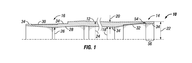
[0013] Figure 1 is a partial cross-sectional view of an expandable tubular
member.
2
CA 03068322 2019-12-20
WO 2019/023535 PCT/US2018/044022
[0014] Figure 2 is a partial cross-sectional view of an expandable threaded
connection in an
unexpanded condition.
[0015] Figure 3 is a partial cross-sectional view of an expandable threaded
connection in an
expanded condition.
DETAILED DESCRIPTION
[0016] It is to be understood that the following disclosure describes
several exemplary
embodiments for implementing different features, structures, or functions of
the invention.
Exemplary embodiments of components, arrangements, and configurations are
described below to
simplify the present disclosure; however, these exemplary embodiments are
provided merely as
examples and are not intended to limit the scope of the invention.
Additionally, the present
disclosure may repeat reference numerals and/or letters in the various
exemplary embodiments and
across the Figures provided herein. This repetition is for the purpose of
simplicity and clarity and
does not in itself dictate a relationship between the various exemplary
embodiments and/or
configurations discussed in the various figures. Moreover, the formation of a
first feature over or on
a second feature in the description that follows may include embodiments in
which the first and
second features are formed in direct contact, and may also include embodiments
in which additional
features may be formed interposing the first and second features, such that
the first and second
features may not be in direct contact. Finally, the exemplary embodiments
presented below may be
combined in any combination of ways, i.e., any element from one exemplary
embodiment may be
used in any other exemplary embodiment, without departing from the scope of
the disclosure.
[0017] Additionally, certain terms are used throughout the following
description and claims to
refer to particular components. As one skilled in the art will appreciate,
various entities may refer to
the same component by different names, and as such, the naming convention for
the elements
described herein is not intended to limit the scope of the invention, unless
otherwise specifically
defined herein. Further, the naming convention used herein is not intended to
distinguish between
components that differ in name but not function. Additionally, in the
following discussion and in
the claims, the terms "including" and "comprising" are used in an open-ended
fashion, and thus
should be interpreted to mean "including, but not limited to." All numerical
values in this disclosure
may be approximate values unless otherwise specifically stated. Accordingly,
various embodiments
of the disclosure may deviate from the numbers, values, and ranges disclosed
herein without
3
CA 03068322 2019-12-20
WO 2019/023535 PCT/US2018/044022
departing from the intended scope. Furthermore, as it is used in the claims or
specification, the term
"or" is intended to encompass both exclusive and inclusive cases, i.e., "A or
B" is intended to be
synonymous with "at least one of A and B," unless otherwise expressly
specified herein.
[0018] Referring initially to Figure 1, an expandable tubular 10 comprises a
main body 12
having a threaded box end 14 and a threaded pin end 16. The main body 12 has
an unexpanded
inner diameter 18 and a wall thickness 20. The box end 14 includes threads 32
formed on its inner
surface that are configured to engage with threads 30 formed on the outer
surface of the pin end 16.
The threads 30, 32 may be any threads suitable for use with expandable
tubulars.
[0019] Pin end 16 has a minimum inner diameter 26 that is smaller than the
inner diameter 18.
The inner diameter along the pin end 16 varies from being smaller near the
base 28 of the thread
and then increases on both sides of the minimum inner diameter 26, that is, on
the side toward the
pin end 16 as well as on the side toward the main body 12. As such, the inner
profile of the pin
end 16 forms a "V" shape having a cusp near the base 28 of threads 30. The
wall thickness of the
pin end 16 varies from being thicker near the main body 12 and then tapering
toward the end of the
pin end 16.
[0020] The box end 14 has an outer diameter 22 that is substantially the same
as an outer diameter
24 of the main body 12. The box end 14 extends beyond the extremity 54 of the
threads 32 over an
unthreaded length 56, which may be approximately 3 times longer than the wall
thickness at the
face 42 of the box end 14. The wall thickness of the box end 14 varies from
being thinner near the
extremity 54 of the threads 32, then increases toward the face 42 of the box
end 14. Accordingly,
the face 42 of the box end 14 is thicker (as compared to conventional flush-
joint connections). The
wall thickness of the box end 14 also increases from the extremity 54 of the
threads 32 toward the
main body 12.
[0021] In certain embodiments, the box end 14 and/or pin end 16 may include
sealing surfaces
34 that are configured to facilitate metal-to-metal sealing engagement of the
threads prior to
expansion.
[0022] Figure 2 shows the box end 14 of one expandable tubular 10A engaged
with the pin end
16 of another expandable tubular 10B to form an expandable tubular assembly
36. A spacer ring
38 is disposed about the pin end 16 in a groove 40 formed between the face 42
of the box end 14
and a shoulder 44 on the pin end 16. The coupled box end 14 and pin end 16
form a threaded
4
CA 03068322 2019-12-20
WO 2019/023535 PCT/US2018/044022
connection 46 that has a minimum inner diameter 26 that is smaller than the
inner diameter 18 of
the main bodies 12. The threaded connection 46 includes metal-to-metal seals
48 at either end of
the engagement of box end 14 and pin end 16.
[0023] The thickness of the threaded connection 46, which is the sum of the
thickness of the box
end 14, and the thickness of the pin end 16 is preferably maximum at the face
42 of the box end 14.
[0024] In operation, an expansion cone (not shown) having an expansion
diameter that is greater
than both inner diameter 18 and minimum inner diameter 26 is moved axially
through the tubular
assembly 36 so as to radially expand the expandable tubular 10B, the threaded
connection 46, and
then the expandable tubular 10A. As shown in Figure 3, once the expansion is
complete, the now
expanded tubular assembly 36 has a substantially uniform inner diameter 50.
After the tubular
assembly 36 is expanded, the box end 14 and the pin end 16 are deformed, and
the metal-to-metal
seals 48 at either end of the engagement of box end 14 and pin end 16 may
open. However, the
face 42 of the box end 14 springs back and the inner surface of box end 14 is
compressed against
the outer surface of the pin end 16. This compression forms a metal-to-metal
seal 52. The location
where the metal-to-metal seal 52 is formed may be different from the initial
location of the metal-
to-metal seals 48.
[0025] Forming the pin end threaded connection on a portion of the tubular
with an inner
diameter less than the main body inner diameter allows the thread to be formed
closer to the center
of the tubular and on a thicker portion of the tubular as compared to
conventional flush-joint
threaded connections. This also allows the box end threaded connection to be
formed closer to the
center of the tubular (as compared to conventional flush-joint connections),
which provides thicker
material at the end of the tubular that can be utilized to create the metal-to-
metal seal described
herein. Thus, the disclosed embodiment that provides a threaded connection
that has a thicker wall
section as compared to conventional expandable flush-joint connections without
an unacceptable
increase in the expansion forces needed to expand the threaded connection.
Therefore, the
disclosed embodiments provide greater resistance to tensile loads, and
therefore a greater
efficiency, as compared to conventional expandable threaded connections.
[0026] In addition, because of the inner diameter variations along the pin
end, the plastic
deformation of the threaded connection that occurs during expansion may be
larger near the
minimum inner diameter. Further, because of the thickness variation along the
box end, the
CA 03068322 2019-12-20
WO 2019/023535 PCT/US2018/044022
amount of spring-back that occurs after expansion at the extremity of the
threads of the box end
may be less than the amount of spring-back that occurs at the face of the box
end. As such, the
unthreaded length of the box end may rotate and form a new metal-to-metal seal
after expansion.
In some embodiments, the pressure contact at the new metal-to-metal seal may
be sufficient to
prevent the seal from opening under a differential pressure of 10,000 psi or
less between inside and
outside the expanded tubulars.
[0027] In contrast with other known expandable connections having a metal-to-
metal seal, the
expandable connection described herein may be expanded at different expansion
ratio, (i.e., using
any of several expansions cones having different expansion diameters) while
still providing a
metal-to-metal seal after expansion of the threaded connection.
[0028] While the disclosure is susceptible to various modifications and
alternative forms,
specific embodiments thereof are shown by way of example in the drawings and
description. It
should be understood, however, that the drawings and detailed description
thereto are not intended
to limit the disclosure to the particular form disclosed, but on the contrary,
the intention is to cover
all modifications, equivalents and alternatives falling within the spirit and
scope of the present
disclosure.
6