Note: Descriptions are shown in the official language in which they were submitted.
CA 03068447 2019-12-23
CWCAS-596
WET FLUE GAS DESULFURIZATION PROCESS AND APPARATUS
BACKGROUND OF THE INVENTION
[0002] The present invention generally relates to systems, apparatuses, and
processes for removing acidic gases from gas streams, including but not
limited to
utility and industrial flue gases. The invention particularly relates to the
control of
free ammonia and ammonium sulfate aerosol in wet flue gas desulfurization
processes and apparatuses in which an ammonia-containing scrubbing solution is
used to produce ammonium sulfate as a byproduct.
[0003] Gas-liquid contactors and absorbers are widely used to remove
substances such as gases and particulate matter from flue gases produced by
utility and industrial plants. Often of particular concern are sulfur dioxide
(S02)
and other acidic gases produced by the combustion of fossil fuels and various
industrial operations. These gases are known to be hazardous to the
environment and their emission into the atmosphere is closely regulated by
clean
air statutes. The method by which these gases are removed with a gas-liquid
contactor or absorber is commonly referred to as wet flue gas desulfurization
(WFGD).
[0004] The cleansing action produced by gas-liquid contactors and absorbers
- 1 -
CA 03068447 2019-12-23
WO 2019/010075
PCT/US2018/040221
is generally derived from the passage of gas through a tower cocurrently or
countercurrently to a descending liquid that absorbs the targeted gas(es) and
particulate matter. Wet flue gas desulfurization processes have typically
involved
the use of an alkaline scrubbing liquid, such as a calcium-based slurry or a
sodium-
based or ammonia-based solution. While effective, gas-liquid contactors and
absorbers utilizing calcium-based slurries produce large quantities of wastes
or
gypsum, the latter having only nominal commercial value. In contrast, ammonia-
based scrubbing processes have been used in the art to produce a more valuable
ammonium sulfate byproduct that is usable as a fertilizer. In these processes,
sulfur dioxide is absorbed from flue gases with an ammonium sulfate solution,
after
which the sulfur dioxide is reacted with oxygen and anhydrous or aqueous
ammonia injected into the solution to form additional ammonium sulfate
solution or
ammonium sulfate crystals ((NH4)2SO4). Particular examples of such processes
are disclosed in United States Patent Nos. 4,690,807, 5,362,458, 6,187,278,
6,277,343, 7,771,685, and 9,327,234. In addition to being required to react
with
sulfur dioxide to produce ammonium sulfate, ammonia also serves to increase
the
efficiency of sulfur dioxide removal by reducing the acidity of the ammonium
sulfate
solution, which becomes more acidic with the absorption of sulfur dioxide.
[0005] The use and addition of anhydrous or aqueous ammonia to control
sulfur
oxide gases can result in undesirable levels of ammonia slip. As used herein,
ammonia slip refers to free ammonia (anhydrous ammonia, NH3) entrained in a
scrubbed flue gas exiting a gas contactor or absorber. In addition to
incurring an
economic loss because of lost ammonia, free ammonia in the scrubbed flue gas
reacts with uncaptured sulfur dioxide and trioxide to create an ammonium
sulfate
aerosol that may be visible as a blue or white plume in the stack discharge,
leading
to secondary pollution problems. Controlling the amount of free ammonia in the
desulfurization process is in part a function of the ammonia vapor pressure,
which
results from a combination of pH and levels of unoxidized ammonium sulfite
- 2 -
CA 03068447 2019-12-23
WO 2019/010075
PCT/US2018/040221
produced by the reaction of sulfur dioxide and ammonia in the absence of
sufficient
oxygen. High pH values result in high ammonia vapor pressure, which promotes
ammonia slip. High levels
of unoxidized ammonium sulfite also promote
ammonia slip.
[0006] FIGS. 1 and
2 schematically represent a flue gas scrubbing apparatus
that is disclosed in U.S. Patent No. 6,187,278 as effective to reduce ammonia
slip. As shown, the apparatus 10 includes an upright absorber 12 that is
supplied
with flue gas through an inlet duct 14. The apparatus 10 operates in a manner
that causes absorption of sulfur dioxide from the flue gas using a scrubbing
liquid.
The scrubbed flue gas that leaves the absorber 12 can be delivered to a stack
(not
shown) or other suitable equipment through an outlet duct 20. The source of
the
flue gas may be any process involving the combustion of fossil fuels or
various
industrial operations in which undesirable gases or particulate matter are
produced.
[0007] U.S. Patent
No. 6,187,278 discloses the apparatus 10 as utilizing an
ammonia-rich scrubbing solution 22, such as an aqueous ammonium sulfate
solution containing free dissolved ammonia as the reagent for the
desulfurization
process. FIG. 1 shows ammonia (NH3) being delivered from a source 32 to a
reaction tank 18 via a pump 26, conduit 28, and injection system 30 that
comprises
multiple spargers 34 that extend across the entire diameter of the tank 18. A
recirculation pump 40 serves to recycle the scrubbing solution 22 from the
tank 18
through a conduit 16 to a contactor region of the absorber 12, where the
solution
22 is introduced through a number of nozzles 24 or other suitable devices. The
scrubbing process involves spraying the scrubbing solution 22 into the
absorber
12 so as to provide intimate contact between the solution 22 and the flue gas.
As
a result, the solution 22 absorbs sulfur dioxide and other acid gases, such as
hydrogen chloride (HCI) and hydrogen fluoride (HF), if they are present in the
flue
- 3 -
CA 03068447 2019-12-23
WO 2019/010075
PCT/US2018/040221
gas. The solution 22 then falls into the reaction tank 18, where the absorbed
sulfur dioxide reacts with the ammonia and is oxidized to form ammonium
sulfate.
Specifically, sulfur dioxide reacts with ammonia to form ammonium sulfite
((NH4)2503) and ammonium bisulfite (NH4HS03), which are oxidized in the
presence of sufficient oxygen to form ammonium sulfate and ammonium bisulfate
(NH4HSO4), the latter of which reacts with ammonia to form additional ammonium
sulfate. A portion of the scrubbing solution 22 and/or ammonium sulfate
crystals
that form in the solution 22 can then be drawn off to yield the desired
byproduct of
this reaction. A sufficient amount of ammonium sulfate may be removed from the
scrubbing solution 22 prior to delivery to the absorber 12 in order to
maintain
ammonium sulfate at a desired concentration in the solution 22.
[0008] U.S. Patent
No. 6,187,278 teaches that the manner in which ammonia
is injected may promote high levels of ammonia slip, such that ammonia and
possibly ammonium sulfate aerosol are discharged into the atmosphere with the
scrubbed flue gas exiting the absorber 12. As a solution to this problem, U.S.
Patent No. 6,187,278 injects ammonia into the scrubbing solution 22 in the
reaction
tank 18 in a dilute form (for example, a dilute aqueous solution) and through
the
spargers 34 shown in FIGS. 1 and 2, which uniformly disperse the dilute
ammonia
in the scrubbing solution 22 to reduce the likelihood that pockets of high pH
and
high ammonium sulfite levels will be present in the scrubbing solution 22,
such that
more uniform and desirable pH and ammonium sulfite levels are achieved that
promote absorption of ammonia and control ammonia slip in the absorber 12. As
represented in FIG. 1, the ammonia injected into the scrubbing solution 22 is
diluted with oxygen from a suitable source 38, and the resulting mixture is
then
delivered to the tank 18 via the spargers 34 of the injection system 30.
Circulation
of the injected ammonia and oxygen in the reaction tank 18 is shown in FIG. 1
as
promoted by a fan 42.
- 4 -
CA 03068447 2019-12-23
WO 2019/010075
PCT/US2018/040221
BRIEF DESCRIPTION OF THE INVENTION
[0009] The present
invention provides systems, apparatuses, and processes
suitable for controlling free ammonia in wet flue gas desulfurization
processes and
apparatuses in which an ammonia-containing scrubbing solution is used to
produce ammonium sulfate.
[0010] According
to one aspect of the invention, an apparatus for removing
sulfur dioxide from a flue gas includes an absorber having a contactor region
through which a flue gas comprising sulfur dioxide is able to flow and a
reaction
tank containing a scrubbing solution comprising ammonium sulfate. The tank has
a sidewall that defines a perimeter of the tank and a bottom wall that defines
a
bottom of the tank. A plurality of lance-agitator units are distributed around
the
perimeter of the tank. Each lance-agitator unit comprises a lance that injects
a
mixture of oxygen and a dilute ammonia-containing fluid toward the bottom of
the
tank and an agitator that agitates the mixture and propels the mixture toward
the
bottom of the tank. The apparatus further includes a source of the mixture of
oxygen and dilute ammonia-containing fluid, and means for recirculating the
scrubbing solution from the tank to the contactor region.
[0011] According
to another aspect of the invention, a process for removing
sulfur dioxide from a flue gas includes delivering the flue gas to a contactor
region
of an absorber, contacting the flue gas within the contactor region with a
scrubbing
solution that contains ammonium sulfate to absorb sulfur dioxide from the flue
gas,
and accumulating the scrubbing solution containing the absorbed sulfur dioxide
in
a tank having a bottom wall and a side wall that defines a perimeter of the
tank.
A plurality of lance-agitator units is distributed around the perimeter of the
tank to
introduce a mixture of oxygen and a dilute ammonia-containing fluid into the
tank
to react with the sulfur dioxide to produce ammonium sulfate. Each lance-
agitator
- 5 -
CA 03068447 2019-12-23
WO 2019/010075
PCT/US2018/040221
unit comprises a lance that injects the mixture toward the bottom of the tank
and
an agitator that agitates the mixture and propels the mixture toward the
bottom of
the tank. The scrubbing solution is recirculated from the tank to the
contactor
region.
[0012] Technical aspects of the processes and apparatuses described above
preferably include the ability to generate ammonium sulfate while controlling
ammonia slip through the combined use of multiple lances and agitators, which
have been shown to be effective and offer advantages over prior art sparger
systems.
[0013] Other aspects and advantages of this invention will be further
appreciated from the following detailed description.
BRIEF DESCRIPTION OF THE DRAWINGS
[0014] FIG. 1 is a schematic representation of an apparatus for a flue gas
desulfurization process, and FIG. 2 is a cross-sectional view of the apparatus
of
FIG. 1 along section line 2-2.
[0015] FIG. 3 is a schematic representation of an apparatus for a flue gas
desulfurization process in accordance with a nonlimiting aspect of the present
invention, and FIG. 4 is a cross-sectional view of the apparatus of FIG. 3
along
section line 4-4.
DETAILED DESCRIPTION OF THE INVENTION
[0016] The invention relates to flue gas desulfurization processes and
apparatuses suitable for removing sulfur dioxide gas entrained in flue gases
to
- 6 -
CA 03068447 2019-12-23
WO 2019/010075
PCT/US2018/040221
generate ammonium sulfate as a byproduct. While the invention will be
described
in reference to a desulfurization system that utilizes an absorber, those
skilled in
the art will recognize that the teachings of this invention can be readily
applied to
various other desulfurization systems, and the desulfurization process is
compatible with various systems capable of removing other undesirable gases,
mist, dust, fumes, smoke and/or particulate matter from a stream of gas.
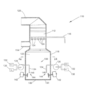
[0017] FIG. 3 is a
schematic view of a flue gas scrubbing apparatus 110 in
accordance with a nonlimiting embodiment of the invention. As shown, the
apparatus 110 includes an upright absorber 112 that is supplied with a flue
gas
through an inlet duct 114. The apparatus 110 operates in a manner that causes
absorption of sulfur dioxide from the flue gas through the use of a scrubbing
solution 122. The scrubbed flue gas exits the absorber 112 through an outlet
duct
120 and from there may be delivered to a stack (not shown) or other suitable
equipment. The source of the flue gas may be any process involving the
combustion of fossil fuels or various industrial operations by which
undesirable
gases or particulate matter are produced.
[0018] The
scrubbing solution 122 is an ammonia-rich scrubbing solution, and
in particular a scrubbing solution containing free dissolved ammonia as the
reagent
for the desulfurization process. The dissolved ammonia can be either aqueous
ammonia (ammonium hydroxide) or anhydrous ammonia (NH3), depending on the
composition of the scrubbing solution. As nonlimiting examples, the solution
may
contain ammonia diluted with air and/or water, with the latter resulting in
the
presence of aqueous ammonia. FIG. 3 shows ammonia being delivered from a
source 132 to a reaction tank 118 via a pump 126 and an injection system 130.
The ammonia, which may be present in an aqueous solution or other suitable
solution as noted above, is a primary reactant when producing ammonium sulfate
as a byproduct of the desulfurization process, and the scrubbing solution 122
- 7 -
CA 03068447 2019-12-23
WO 2019/010075
PCT/US2018/040221
serves as the vehicle for delivering the ammonia to the absorber 112.
[0019] Similar to
the apparatus 10 of FIG. 1, one or more recirculation pumps
140 (FIG. 4) may be used to recycle the scrubbing solution 122 from the tank
118
through a conduit 116 to a contactor region of the absorber 112, where the
solution
122 is introduced through a number of nozzles 124 or other suitable devices.
The
scrubbing process involves spraying the scrubbing solution 122 into the
absorber
112 so as to provide intimate contact between the solution 122 and the flue
gas.
As a result, the solution 122 absorbs sulfur dioxide and potentially other
acid
gases, such as hydrogen chloride and hydrogen fluoride, if present in the flue
gas.
The solution 122 then falls into the reaction tank 118, where the absorbed
sulfur
dioxide reacts with the ammonia to form ammonium sulfite and ammonium
bisulfite, which are then oxidized in the presence of sufficient oxygen to
form
ammonium sulfate and ammonium bisulfate, the latter of which reacts with
ammonia to form additional ammonium sulfate. A portion of the scrubbing
solution 122 and/or ammonium sulfate crystals that form in the solution 122
may
be drawn off to yield a desired fertilizer byproduct of this reaction. A
sufficient
amount of ammonium sulfate is preferably removed from the scrubbing solution
122 prior to delivery to the absorber 112 in order to maintain ammonium
sulfate at
a desired concentration in the solution 122, as a nonlimiting example, about
2%
up to the saturation level of ammonium sulfate in the solution 122.
[0020] Sufficient
ammonia is preferably delivered to the tank 118 to control the
pH of the scrubbing solution 122, for example, within a typical range of about
4 to
6 pH range, such that the solution 122 is highly reactive for high efficient
capture
of sulfur oxide gases. The manner in which the ammonia is injected into the
solution 122 can undesirably promote high levels of ammonia slip, such that
free
ammonia and potentially an ammonium sulfate aerosol escapes the absorber 112
and is discharged into the atmosphere. Whereas U.S. Patent No. 6,187,278
- 8 -
CA 03068447 2019-12-23
WO 2019/010075
PCT/US2018/040221
seeks to reduce ammonia slip by injecting dilute ammonia into a scrubbing
solution
with an injection system that comprises multiple spargers that extend in
parallel
across the entire diameter of the reaction tank (FIGS. 1 and 2), a substantial
test
program leading up to the present invention indicated that combinations of
lances
and agitators selectively located around the perimeter of a reaction tank are
capable of having a comparable effect with respect to oxygen transfer and
uniformly dispersing a dilute mixture of ammonia and oxygen in the reaction
tank.
[0021] The ammonia
injected from the source 132 in the reaction tank 118 is
preferably in the form of a dilute solution, for example, an aqueous solution.
FIGS. 3 and 4 represent the diluted ammonia solution as being further diluted
with
oxygen from a suitable source 138 prior to being injected into the tank 118
via
lances 134 of the injection system 130. Air is a suitable source for the
oxygen,
with a preferred ammonia:air weight ratio being about 1 to about 5. As seen in
FIG. 3, each lance 134 is paired with an agitator 142 that operates in
combination
with its associated lance 134 to uniformly disperse the injected mixture of
oxygen
and dilute ammonia toward the bottom 136 of the reaction tank 118. Each lance
134 is represented in FIG. 3 as comprising a pipe that extends through a
sidewall
of the tank 118, has a section that projects vertically downward toward the
tank
bottom 136, and terminates with an outlet 148 facing the tank bottom 136. Each
agitator 142 is represented in FIG. 3 as comprising a propeller or fan mounted
on
a shaft that extends through the tank sidewall at a negative angle to
horizontal and
is driven by a motor. Each lance 134 injects the ammonia toward the bottom 136
of the tank 118, and its paired agitator 142 assists to propel and disperse
the
injected ammonia at the tank bottom 136. The negative angle of the shaft is
preferably sufficient to promote the downward flow of the injected oxygen-
ammonia mixture toward the tank bottom 136, with suitable angles believed to
be
at least eight to about twelve degrees from horizontal.
- 9 -
CA 03068447 2019-12-23
WO 2019/010075
PCT/US2018/040221
[0022] FIG. 4 represents the tank 118 as equipped with four lance/agitator
units
144, each having a single lance 134 paired with a single agitator 142. As
represented in FIG. 4, the units 144 are generally equi-angularly distributed
around
the interior perimeter 146 defined by the sidewall of the tank 118. Based on a
reaction tank 118 having a depth of about 48 feet (about 14 meters), the
outlet 148
of each lance 134 is preferably located about 4 to about 8 feet (about 1.2 to
about
2.4 meters) from the bottom 136 of the tank 118, and agitation caused by each
agitator 142 preferably occurs between the lance outlet 148 and the tank
bottom
136. This arrangement has been shown to achieve acceptable results in terms of
delivering sufficient ammonia and oxygen while simultaneously avoiding ammonia
slip. The ammonia and oxygen mixture introduced with the injection system 130
is forcibly circulated through the reaction tank 118 by the agitators 142, as
opposed
to relying on natural circulation cause by the solution 122 being recirculated
from
the tank 118 to the absorber 112.
[0023] A significant advantage of the present invention is the ability to
use
lances instead of more expensive spargers to reduce ammonia slip in a
desulfurization process that uses an ammonia-based scrubbing solution. Other
advantages include minimal pluggage potential, fewer penetrations, and fewer
obstructions in the reaction tank.
[0024] While the invention has been described in terms of a specific or
particular embodiment, it should be apparent that alternatives could be
adopted by
one skilled in the art. For example, the flue gas scrubbing apparatus 110 and
its
components could differ in appearance and construction from the embodiment
described herein and shown in the drawings, functions of certain components of
the apparatus 110 could be performed by components of different construction
but
capable of a similar (though not necessarily equivalent) function, various
process
parameters could be employed, and various materials could be used in the
- 10 -
CA 03068447 2019-12-23
WO 2019/010075
PCT/US2018/040221
fabrication of the apparatus 110 and/or its components. In addition, the
invention
encompasses additional or alternative embodiments in which one or more
features
or aspects of the disclosed embodiment could be eliminated. Accordingly, it
should be understood that the invention is not necessarily limited to any
embodiment described herein or illustrated in the drawings. It should also be
understood that the phraseology and terminology employed above are for the
purpose of describing the illustrated embodiment, and do not necessarily serve
as
limitations to the scope of the invention. Therefore, the scope of the
invention is
to be limited only by the following claims.
- 11 -