Note: Descriptions are shown in the official language in which they were submitted.
CA 03068553 2019-12-27
INFORMATION PROCESSING METHOD, APPARATUS, AND
COMMUNICATION APPARATUS
TECHNICAL FIELD
[0001] Embodiments of the present application relate to the
communications field, and in
particular, to an information processing method and a communication apparatus.
BACKGROUND
[0002] A low density parity check (LDPC) code is a type of linear block
code characterized
by a sparse check matrix, and has a flexible structure and low decoding
complexity. Because a
partially parallel iterative decoding algorithm can be used in decoding an
LDPC coded
codeword, the LDPC code has a higher throughput than a conventional Turbo
code. The LDPC
code may be used as an error correction code in a communication system, so as
to improve
reliability and power utilization in channel-based transmission. The LDPC code
may also be
widely used in spatial communications, optical fiber communications, personal
communication
systems, asymmetrical digital subscriber loop (ADSL), magnetic recording
devices, and the
like. Currently, the LDPC code has been considered as one of channel coding
schemes in the
fifth generation (5G) mobile communication systems.
[0003] In actual applications, LDPC matrices having different special
structures may be
used. An LDPC matrix H, having a special structure, may be obtained by
expanding (also called
lifting) an LDPC base matrix having a quasi cycle (QC) structure . A coding
scheme using QC-
LDPC matrices is suitable for hardware with a high degree of parallelism, and
provides a higher
throughput. The QC-LDPC matrix may be designed to be suitable for channel
coding.
[0004] A coding scheme using QC-LDPC matrices is suitable for hardware
with a high
degree of parallelism, and provides a higher throughput. The QC-LDPC matrix
may be
designed to be suitable for channel coding.
CA 03068553 2019-12-27
SUMMARY
[0005]
Embodiments of the present application provide an information processing
method,
and a communication apparatus and system, so as to support encoding and
decoding of
information bit sequences with a plurality of lengths.
[0006] According to a first aspect, an encoding method and an encoder are
provided. The
encoder encodes an input sequence by using a low density parity check (LDPC)
matrix.
[0007]
According to a second aspect, a decoding method and a decoder are provided.
The
decoder decodes an input sequence by using an LDPC matrix.
[0008] In
a first implementation of the first aspect or the second aspect, the LDPC
matrix
is obtained based on a lifting factor Z and a base matrix.
[0009]
Based on the foregoing implementation, a base matrix of a base graph includes
one
of the following:
the base matrix includes row 0 to row 6, column 0 to column 16 of one of
matrices shown
in FIGs. 3b-1 to 3b-8, or
the base matrix includes row 0 to row 6, some columns of column 0 to column 16
in one
of matrices shown in FIGs. 3b-1 to 3b-8, or
the base matrix is a matrix obtained by performing row/column transformation
on row 0
to row 6 column 0 to column 16 in one of matrices shown in FIGs. 3b-1 to 3b-8,
or
the base matrix is a matrix obtained by performing row/column transformation
on row 0
to row 6, some columns of column 0 to column 16 in one of matrices shown in
FIGs. 3b-1 to
3b-8.
[0010] To
support different code block lengths, different lifting factors Z are needed
for an
LDPC code. Based on the foregoing implementations, base matrices corresponding
to different
lifting factors Z are used based on the different lifting factors Z. In some
implementations,
Z=ax2J, where 05.,j<7, and aEl {2,3,5,7,9,11,13,15}.
[0011]
Further, based on the foregoing implementations, the LDPC matrix may be
obtained
based on a lifting factor Z and a matrix Hs that is obtained by offsetting the
foregoing base
matrix. Alternatively, the LDPC matrix may be obtained based on a lifting
factor Z and a matrix
that is obtained by performing row/column transformation on a matrix Hs, and
Hs is obtained
by offsetting the foregoing base matrix. The offsetting the foregoing base
matrix may be
increasing or decreasing a shift value greater than or equal to 0 in one or
more columns by an
offset.
2
CA 03068553 2019-12-27
[0012] The base graph and the base matrix of the LDPC matrix in the
foregoing
implementations can satisfy a performance requirement of code blocks of a
plurality of block
lengths.
[0013] The lifting factor Z may be determined by the encoder or the
decoder based on a
length K of the input sequence, or may be determined by another device and
provided to the
encoder or the decoder as an input parameter. Optionally, the LDPC matrix may
be obtained
based on the obtained lifting factor Z and a base matrix corresponding to the
lifting factor Z.
[0014] In a second implementation of the first aspect or the second
aspect, the LDPC matrix
is obtained based on the lifting factor Z and parameter(s) of the LDPC matrix.
[0015] The parameters of the LDPC matrix may include a row index, a column
index of a
column in which a non-zero-element is located, and a shift value of the non-
zero-element. The
parameters are stored in manners like row 0 to row 6 in one of Table 2 and
Table 3b-I to Table
3b-8. The parameters of the LDPC matrix may further include a row weight.
Locations of non-
zero-elements in columns are in a one-to-one correspondence with shift values
of the non-zero-
elements.
[0016] For a communication device at a transmitting side, the encoding an
input sequence
by using an LDPC matrix may include: encoding the input sequence by using an
LDPC matrix
corresponding to the lifting factor Z; or encoding an input sequence by using
a matrix that is
obtained by performing row/column transformation on an LDPC matrix
corresponding to the
lifting factor Z. The row/column transformation in this application means row
transformation,
column transformation, or row transformation and column transformation.
[0017] For a communication device at a receive side, the decoding an
input sequence by
using an LDPC matrix may include: decoding the input sequence by using an LDPC
matrix
corresponding to the lifting factor Z; or decoding the input sequence by using
a matrix that is
obtained by performing row/column transformation on an LDPC matrix
corresponding to the
lifting factor Z. The row/column transformation in this application means row
transformation,
column transformation, or row transformation and column transformation.
[0018] In a possible implementation, an LDPC matrix may be stored, and
the LDPC matrix
is used to encode the input sequence, or an LDPC matrix that can be used for
encoding is
obtained by performing transformation (row/column transformation) or lifting
based on the
LDPC matrix.
[0019] In another possible implementation, a parameter or parameters may
be stored, and
an LDPC matrix used for encoding or decoding may be obtained based on the
parameter, so
that the input sequence can be encoded or decoded based on the LDPC matrix.
The parameter
3
CA 03068553 2019-12-27
or parameters include at least one of the following: a base graph, a base
matrix, a transformed
matrix obtained by performing row/column transformation on a base graph or a
base matrix, a
lifting matrix based on a base graph or a base matrix, a shift value of a non-
zero-element in a
base matrix, or any parameter used to obtain the LDPC matrix.
[0020] In still another possible implementation, the base matrix of the
LDPC matrix may
be stored in a memory.
[0021] In yet another possible implementation, the base graph of the
LDPC matrix may be
stored in a memory, and the shift value of the non-zero-element in the base
matrix of the LDPC
matrix may be stored in the memory.
[0022] In still yet another possible implementation, the parameter of the
LDPC matrix is
stored in a memory in manners like Table 2 or Table 3b-1 to Table 3b-8, or
some element groups
of the parameter may be stored.
[0023] Based on the foregoing possible implementations, in a possible
design, at least one
of a base graph and a base matrix used for LDPC encoding or decoding is
obtained by
performing row transformation, or column transformation, or row transformation
and column
transformation on at least one of the base graph and the base matrix of the
LDPC matrix.
[0024] According to a third aspect, a communication apparatus is
provided. The
communication apparatus may include software modules and/or hardware
components
configured to perform the foregoing method designs.
[0025] In a possible design, the communication apparatus provided in the
third aspect
includes a processor and a transceiver component. The processor and the
transceiver component
may be configured to perform any one of the possible implementations of the
encoding method
or the decoding method. The communication apparatus may be a terminal, a base
station, or
another network device, and the transceiver component of the communication
apparatus may
be a transceiver. The communication apparatus may be a baseband chip or a
baseband board,
and the transceiver component of the communication apparatus may be an
input/output circuit
of the baseband chip or the baseband board, and is configured to receive/send
an input/output
signal. Optionally, the communication apparatus may further include a memory,
configured to
store data and/or instructions.
[0026] In an implementation, the processor may include the encoder
according to the first
aspect and a determining unit. The determining unit is configured to determine
a lifting factor
Z required to encode an input sequence. The encoder is configured to encode
the input sequence
by using an LDPC matrix corresponding to the lifting factor Z.
4
CA 03068553 2019-12-27
[0027] In another implementation, the processor may include the decoder
according to the
second aspect and an obtaining unit. The obtaining unit is configured to
obtain a soft value of
an LDPC code and a lifting factor Z. The decoder is configured to decode the
soft value of the
LDPC code based on a base matrix HB corresponding to the lifting factor Z, to
obtain an
information bit sequence.
[0028] According to a fourth aspect, a communication apparatus is
provided. The
communication apparatus includes one or more processors. In a possible design,
the one or
more processors configured to perform any one of the possible implementations
of the encoder
according to the first aspect. In another possible design, the encoder
according to the first aspect
may be a part of the processor. In addition to the functions of the encoder
according to the first
aspect, the processor can further implement other functions. In a possible
design, the one or
more processors can implement functions of the decoder according to the second
aspect. In
another possible design, the decoder according to the second aspect may be a
part of the
processor.
[0029] Optionally, the communication apparatus may further include a
transceiver and an
antenna. Optionally, the communication apparatus may further include a
component for
transport block cyclic redundancy check (CRC), a component for code block
segmentation and
CRC check, an interleaver for interleaving, a modulator for modulation
processing, or the like.
In a possible design, functions of these components may be implemented by
using the one or
more processors.
[0030] Optionally, the communication apparatus may further include a
demodulator for a
demodulation operation, a deinterleaver for deinterleaving, a component for
rate de-matching,
or the like. Functions of these devices may be implemented by using the one or
more processors.
[0031] According to a fifth aspect, an embodiment of the present
application provides a
communication system. The system includes the communication apparatus
according to the
third aspect.
[0032] According to a sixth aspect, an embodiment of the present
application provides a
communication system. The system includes one or more communication
apparatuses
according to the fourth aspect.
[0033] According to still another aspect, an embodiment of the present
application provides
a computer storage medium. The computer storage medium stores a program, and
when the
program is run, a computer is caused to perform the methods described in the
foregoing aspects.
5
CA 03068553 2019-12-27
[0034] Yet another aspect of this application provides a computer program
product
including one or more instructions, which when executed by computer, cause the
computer to
perform the methods according to the foregoing aspects.
[0035] According to the information processing method, the apparatus, the
communication
device, and the communication system in the embodiments of the present
application, flexible
code length and code rate requirements of a system can be met in terms of
encoding
performance and an error floor.
BRIEF DESCRIPTION OF DRAWINGS
[0036] FIG. 1 shows examples of a base graph, a base matrix, and circular
permutation
matrices that are used in LDPC code;
[0037] FIG. 2 is a schematic structural diagram of a base graph that is
used in LDPC code;
[0038] FIG. 3a is a schematic diagram of a base graph that is used in
LDPC code according
to an embodiment of the present application;
[0039] FIG. 3b-1 is a schematic diagram of a base matrix according to an
embodiment of
the present application;
[0040] FIG. 3b-2 is a schematic diagram of another base matrix according
to an
embodiment of the present application;
[0041] FIG. 3b-3 is a schematic diagram of another base matrix according
to an
embodiment of the present application;
[0042] FIG. 3b-4 is a schematic diagram of another base matrix according to
an
embodiment of the present application;
[0043] FIG. 3b-5 is a schematic diagram of another base matrix according
to an
embodiment of the present application;
[0044] FIG. 3b-6 is a schematic diagram of another base matrix according
to an
embodiment of the present application;
[0045] FIG. 3b-7 is a schematic diagram of another base matrix according
to an
embodiment of the present application;
[0046] FIG. 3b-8 is a schematic diagram of another base matrix according
to an
embodiment of the present application;
[0047] FIG. 4 is a performance diagram provided by an embodiment of the
present
application;
6
CA 03068553 2019-12-27
[0048] FIG. 5 is a flowchart of an information processing procedure
according to an
embodiment of the present application;
[0049] FIG. 6 is a flowchart of an information processing procedure
according to an
embodiment of the present application;
[0050] FIG. 7 is a simplified block diagram of a communication apparatus
according to an
embodiment of the present application; and
[0051] FIG. 8 is a block diagram of a communication system according to
an embodiment
of the present application.
DETAILED DESCRIPTION OF EMBODIMENTS
[0052] For ease of understanding, the following describes some terms used
in this
application.
[0053] In this application, terms "network" and "system" are often
interchangeably used,
"apparatus" and "device" are often interchangeably used, and "information" and
"data" are also
often interchangeably used. Means of these terms are conventionally
understood. A
"communication apparatus" may refer to a chip (for example, a baseband chip, a
digital signal
processing chip, or a general-purpose chip), a terminal, a base station, or
other network devices.
A terminal is a device having communication functions. A terminal may be a
handheld device,
an in-vehicle device, a wearable device, or other kinds of devices that have
wireless
communication functions. A terminal may be called by different names in
different networks,
such as user equipment, mobile station, subscriber unit, station, cellular
phone, personal digital
assistant, wireless modem, wireless communication device, handheld device,
laptop computer,
cordless telephone set, or wireless local loop station. For ease of
description, these devices are
collectively referred to as a terminal in this application. A base station
(base station, BS) or
referred to as a base station device is a device deployed in a radio access
network to provide
wireless communication functions. The base station may be called by different
names in
different wireless access systems. For example, a base station in a Universal
Mobile
Telecommunications System (UMTS) network is referred to as a NodeB. A base
station in a
long term evolution (LTE) network is referred to as an evolved NodeB (eNB or
eNodeB). A
base station in a new radio (NR) network is referred to as a transmission
reception point (TRP)
or a next generation NodeB (gNB). Base stations in other networks may be
called by other
names. This is not limited in the present application.
7
CA 03068553 2019-12-27
[0054] The technical solutions in the embodiments of the present
application are described
below with reference to the accompanying drawings.
[0055] An LDPC code can be defined by a parity check matrix H. In an
implementation,
the parity check matrix H for LDPC code, also referred to as a LDPC matrix, is
represented by
a matrix called a base graph, and each element in the base graph represents a
ZxZ spreading
(lifting) matrix. Z is a positive integer, and is referred to as a lifting
factor. Z may also be referred
to as a lifting size or the like. The base graph is used to indicate locations
of zero-elements and
non-zero-elements. Each non-zero-element in the base graph corresponds to a
shift value. The
parity check matrix H for the LDPC code may be obtained based on the base
graph and shift
values. Usually, a base graph includes mxn matrix elements (also called
entries), and is
represented by a matrix of m rows and n columns. A value of each matrix
element is either 0 or
1. An element whose value is 0 is called a zero-element, which corresponds to
a Z column x Z
row all-zero matrix. An element whose value is 1 is called a non-zero-element,
which
corresponds to a Z column x Z row circular permutation matrix. In other words,
each element
of the base graph represents either an all zero matrix or a circular
permutation matrix. In the
base graph example 10a shown in FIG. 1, m=7 and n=17, and the base graph 10a
has a QC
structure. It should be noted that, throughout this application, row indexes
and column indexes
of base graphs and base matrices are numbered starting from 0, and this is
merely for ease of
description. For example, column index 0 represents a first column in a base
graph or a base
matrix, column index 1 represents a second column in the base graph or the
base matrix, row
index 0 represents a first row in the base graph or the base matrix, row index
1 represents a
second row in the base graph or the base matrix, and so on.
[0056] It may be understood that the rows and the columns may
alternatively be numbered
starting from 1. In this case, row indexes and column indexes shown in this
specification are
increased by 1 accordingly. For example, if row indexes and column indexes are
numbered
starting from 1, column 1 represents a first column in the base graph and the
matrix, column 2
represents a second column in the base graph and the matrix, row 1 represents
a first row in the
base graph and the matrix, row 2 represents a second row in the base graph and
a matrix, and
so on.
[0057] In another implementation, a base matrix of m rows and n columns may
be defined,
and is sometimes referred to as a PCM (parity check matrix). For example, any
matrix provided
in FIG. 3b-1 to FIG. 3b-8 or a matrix including some rows and columns in any
matrix in FIG.
3b-1 to FIG. 3b-8 is defined. Elements in the base matrix are in a one-to-one
correspondence
with elements in the base graph. A zero-element in the base graph has a same
position in the
8
CA 03068553 2019-12-27
base matrix. In the base matrix, a zero-element may be represented by ¨1 or
"null". A location
of a non-zero-element in row i and column j, whose value is 1 in the base
graph has a same
position in the base matrix, and the non-zero-element is represented as Vij. A
value of Vij in the
base matrix may be defined by a system or may be predefined, or Vij may be
obtained based
on a shift value PI j of a non-zero-element in the base graph and a lifting
factor Z. 13, j is a shift
value corresponding to a predetermined or particular lifting factor Z.13, j
may be obtained based
on Z and V. In an implementation, 13,j and VL, satisfy the following
relationship:
P, j=mod(V,d, Z)
where i and j represent a row index and a column index of the non-zero
element, and indicate a
location of the element in the base matrix.
[0058] In the embodiments of this application, sometimes the base matrix
is also referred
to as a shift matrix of the base graph. The base matrix may be obtained
according to the base
graph and the shift value. If an element in row i and column j of the base
graph has a value 1,
and a shift value of the element is 13,j, where 13, j is an integer greater
than or equal to 0, it
indicates that the element can be replaced by a ZxZ circular permutation
matrix corresponding
to P. The circular permutation matrix may also be referred to as a shift
matrix. The circular
permutation matrix may be obtained by circularly shifting a ZxZ identity
matrix to the right or
to the left for Pij times. In an implementation,
j=mod(V, j, Z)
where V, j is a value in the base matrix, that is corresponding to a non-zero-
element in the base
graph. Sometimes, Vij may also be referred to as a shift value, a cyclic shift
value, or a shift
coefficient. Vtj may be, for example, a shift value corresponding to a maximum
lifting factor
Z.. Z. is a maximum value in a value set of Z. If a value of an element in row
i and column
j in the base graph is 0, the element may be replaced with a ZxZ all zero
matrix. If a value of
an element in row i and column j in the base graph is 1, the element may be
replaced with a
ZxZ circular permutation matrix having the shift value of P, j. In this way, a
parity check matrix
H for the LDPC code is obtained. Z is a positive integer, and may be referred
to as a lifting
factor, a lifting size, or the like. Z may be determined based on a code block
size and an
information data size that are supported by a system. It can be seen that for
a base graph of m
rows x n columns, a size of the parity check matrix H for the LDPC code is
(mxZ) rows x(nxZ)
columns. For example, if the lifting factor Z is 4, each zero-element is
replaced with an all zero
matrix of size 4x4 (see II a of FIG. 1). If P2,3=2, a non-zero-element in row
2 and column 3 of
the base matrix is replaced with a 4x4 circular permutation matrix lid of FIG.
1. The matrix
lid is obtained by circularly shifting a 4x4 identity matrix lib rightward
twice. If P2A=0, a
9
CA 03068553 2019-12-27
non-zero-element in row 2 and column 4 is replaced with the identity matrix
lib. It should be
noted that, this example is merely for illustration, and is not intended to
impose a limitation.
[0059] Value of P, j may depend on the lifting factor Z. For an element
of 1 in the base
graph, Pij may be different for different lifting factors Z. A base matrix
corresponding to the
base graph I0a is shown by 10b in FIG. 1. For example, for a value of 1 in row
1 and column
3 in the base graph 10a, a corresponding shift value Vij in row 1 and column 3
in the base matrix
10b is 27. The value of Pij may be obtained according to P, j=mod(V,,j, Z). In
this way, an
element in row 1 and column 3 can be replaced with a circular permutation
matrix that is
obtained by circularly shifting an identity matrix of size ZxZ rightward or
leftward for 13, j times.
[0060] Usually, the base graph or the base matrix for the LDPC code may
further include p
columns of built-in puncture column, where p may be an integer from 0 to 2.
These columns
may be used in encoding, but the encoded system bits corresponding to the
built-in puncture
columns are not sent. In this case, a code rate of the base matrix for the
LDPC code satisfies
R=(n-m)/(n-p). Using the base graph 10a as an example, if there are two built-
in puncture
columns, the code rate is (17-7)/(17-2)=0.667, which is approximately 2/3.
[0061] An LDPC code used in a wireless communication system is a QC-LDPC
code. A
parity bit part of the QC-LDPC code has a bi-diagonal structure or a raptor-
like structure. This
can simplify encoding and support incremental redundancy hybrid repeat. A
decoder for the
QC-LDPC code usually uses a QC-LDPC shift network (QSN), a Banyan network, or
a Benes
network, to circular shift information.
[0062] A base graph 200 for the QC-LDPC code, which has a raptor-like
structure, is a
matrix of m rows and n columns. The base graph 200 may include five
submatrices A, B, C, D,
and E. A weight of a row or a column of the matrix is determined by quantity
of non-zero-
elements in the row or the column. A weight of a row (row weight) means a
quantity of non-
zero-elements in a row, and a weight of a column (column weight) means a
quantity of non-
zero-elements in a column. The following is shown in base graph 200 of FIG. 2:
[0063] The submatrix A is a matrix of mA rows and nA columns, and a size
of the submatrix
A is mAxnA. Each column corresponds to Z system bits in the LDPC code, and a
system bit is
sometimes referred to as an information bit.
[0064] The submatrix B is a matrix of mA rows and mA columns, and a size of
the submatrix
B is mAxmA. Each column corresponds to Z parity bits in the LDPC code. The
submatrix B
includes a submatrix B' having a bi-diagonal structure and a matrix column
whose column
weight is 3 (weight-3 column for short). The weight-3 column may be located at
the left side of
the submatrix B', as shown by 20a in FIG. 2. The submatrix B may further
include one or more
CA 03068553 2019-12-27
matrix columns whose column weights are 1 (weight-1 column for short). 20b and
20c of FIG.
2 are examples of possible locations of the weight-1 columns.
[0065] Usually, a matrix generated based on the submatrices A and B may
be referred to as
a core matrix, which may be used to support high code-rate encoding.
[0066] The submatrix C is an all zero matrix, and a size of the submatrix C
is mAxmD.
[0067] The submatrix E is an identity matrix, and a size of the
submatrix E is mpxmD,
where mp=m-mA.
[0068] A size of the submatrix D is mpx(nA+mA), and may usually be used
to generate low
code-rate parity bits.
[0069] Because the submatrices C and E have relatively definite structures,
structures of
the three submatrices A, B, and D are some of the factors affecting
encoding/decoding
performance of the LDPC code.
[0070] It may be understood that the foregoing describes the structure
of the base graph/the
base matrix from a perspective of principles. The division of the submatrices
A, B, C, D, and E
is merely to facilitate understanding from the perspective of principles. It
may be understood
that the division of the submatrices A, B, C, D, and E is not limited to the
foregoing division
manner. In an implementation, C is an all zero matrix, E is an identity
matrix, and structures of
C and E are known. Therefore, an LDPC matrix may be represented in a
simplified form without
using all of the submatrices A, B, C, D, and E. For example, the LDPC matrix
may be
represented in a simplified form by the submatrices A, B, and D, by the
submatrices A, B, C,
and D, or by the submatrices A, B, D, and E. In another implementation,
because the submatrix
B includes one or more weight-1 columns, for the one or more weight-1 columns
in the
submatrix B, a structure is relatively definite. Therefore, the one or more
weight-I columns
may not be used to represent the LDPC matrix. For example, the submatrix A,
some columns
in the submatrix B, and corresponding columns in the submatrix D may be used
to represent
the LDPC matrix. When an LDPC matrix having the raptor-like structure is used
for encoding,
a possible implementation is that the part of the matrix including the
submatrices A and B,
namely a core matrix, may first be used in encoding to obtain one or more
parity bits
corresponding to the submatrix B. Then, the entire LDPC matrix is used in
encoding to obtain
one or more parity bits corresponding to the submatrix E. Because the
submatrix B may include
a submatrix B' with bi-diagonal structure and one or more weight-1 columns,
during encoding,
parity bits corresponding to the submatrix B' may be first obtained, and
parity bits
corresponding to the weight-1 columns may be then obtained.
11
CA 03068553 2019-12-27
[0071] An example of an encoding scheme is provided below. Assuming that
the core
matrix including the submatrices A and B is Heore. A last row and a last
column of the H., are
removed. In other words, a weight-1 column and a row in which the non-zero-
element in the
weight-1 column is located are removed from the Wore to obtain a matrix licore-
dual. Parity bits
part of the Hcore-dual is represented as He[Hei He2], where He, is a weight-3
column, and He2
has a bi-diagonal structure. According to a definition of the LDPC matrix,
Hcore-dualiS Pe]T=0,
where S is an input sequence and is represented by a vector of information
bits, P, is a vector
of parity bits, and [S NT represents a transposed matrix formed by the input
sequence S and
Pe. Therefore, parity bits corresponding to &ore-dual may be first calculated
based on the input
sequence S and Hcore-dual, where the input sequence S includes all information
bits. Then, parity
bits corresponding to the one or more weight-1 columns in the submatrix B are
calculated based
on the parity bits corresponding to Hcore-dual and the input sequence S. In
this case, all parity bits
corresponding to the submatrix B may be obtained. Parity bits corresponding to
the submatrix
E are obtained by encoding the submatrix D based on the input sequence S and
the parity bits
corresponding to the submatrix B, to obtain all information bits and all
parity bits. These bits
constitute an encoded sequence, namely, an LDPC codeword.
[0072] The LDPC code may further include a shortening (shortening)
operation or a
puncturing operation on the encoded sequence. The shortened bits or punctured
bits are not
sent.
[0073] Shortening is usually performed starting from the last bit of the
information bits, and
may be performed in different manners. For example, if a quantity of shortened
bits is so, the
last so bits in the input sequence S may be set as known bits, for example,
set to 0, null, or other
value, to obtain an input sequence S'. Then, the input sequence S' is encoded
by using an LDPC
matrix. For another example, the last (so mod Z) bits in the input sequence S
may alternatively
be set as known bits, for example, set as zero, null, or some other value, to
obtain an input
sequence S'. The last so/Z] columns in the submatrix A are deleted to obtain
an LDPC matrix
H', and the input sequence S is encoded by using the LDPC matrix H'; or the
last lso/Z]
columns in the submatrix A do not participate in encoding of the input
sequence S'. After the
encoding, the shortened bits are not sent.
[0074] Puncturing may be performed on built-in puncture bit(s) or parity
bit(s) in the input
sequence. Puncturing parity bit(s) is/are usually performed starting from the
last bit in the parity
bits. Alternatively, puncturing parity bit(s) may be performed according to a
preset puncturing
order of the system. A possible implementation is as follows: The input
sequence is first
encoded, and then, last p bits in the parity bits is/are selected based on a
quantity p of bits that
12
CA 03068553 2019-12-27
need to be punctured, or p bits is/are selected based on the preset puncturing
order of the system.
The p bits is/are not sent. In another possible implementation, alternatively,
p columns in a
matrix that correspond to the punctured bits and p rows in which nonzero
elements in the
columns are located may be determined. These rows and columns do not
participate in
encoding, and no corresponding parity bits are generated.
[0075] It should be noted that the encoding implementation described
herein is merely an
example, and other encoding implementations known to a person skilled in the
art may
alternatively be used based on the base graph and/or the base matrix provided
in embodiments
of this application. This is not limited in this application. Decoding in this
application may be
performed in a plurality of decoding methods, for example, a min-sum (MS)
decoding method
or a belief propagation decoding method may be used. The MS decoding method is
sometimes
referred to as a Flood MS decoding method. For example, the input sequence is
initialized and
then iteration processing is performed. Hard decision detection is performed
after the iteration,
and a check is performed on a hard decision result. If a decoding result
satisfies a check
equation, the decoding succeeds, the iteration ends, and the decision result
is output. If the
decoding result does not satisfy the check equation, iteration processing is
performed again
within a maximum quantity of iterations. If a check still does not pass when
the maximum
quantity of iterations is reached, the decoding fails. A principle of the MS
decoding is
understood by a person skilled in the art, and details are not described
herein.
[0076] It should be noted that the decoding method described herein is
merely an example,
and other decoding methods known by a person skilled in the art may
alternatively be used
based on the base graph and/or the base matrix provided in this application.
The decoding
method is not limited in this application.
[0077] An LDPC codeword is obtained depending on the design of a base
graph or a base
.. matrix. For example, a performance upper limit of an LDPC code may be
determined by
performing density evolution on the base graph or the base matrix. An error
floor of the LDPC
code is determined based on a shift value in the base matrix. The encoding or
decoding
performance can be improved and the error floor can be lowered by properly
designing the base
graph or the base matrix. In the wireless communication systems, code length
is flexible, for
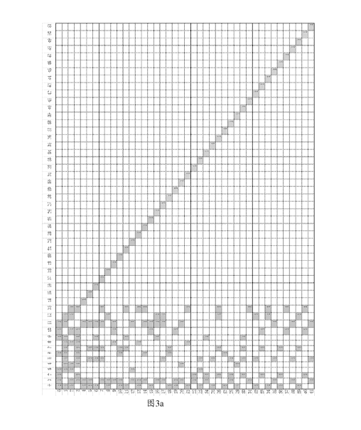
example, 2560 bits or 38400 bits. FIG. 3a shows an example of a base graph for
an LDPC code.
FIGs. 3b-1 to 3b-8 show examples of base matrices corresponding to the base
graph in FIG. 3a.
The base matrices may satisfy performance requirements of a plurality of block
lengths. For
ease of description and understanding, column indexes and row indexes are
respectively shown
on the uppermost side and the leftmost side in . 3a and FIGs. 3b-1 to 3b-8.
13
CA 03068553 2019-12-27
[0078] FIG. 4 is a schematic performance diagram of an LDPC code shown in
FIG. 3a. In
the performance diagram shown in FIG. 4, encoding performance curves using any
one of
matrixes shown in FIGs. 3b-1 to 3b-8 are shown. The horizontal coordinate
represents a length
of an information bit sequence in units of bits, and the vertical coordinate
is a signal-to-noise
ratio (Es/NO) for a symbol required to reach a corresponding block error rate
(BLER). Two lines
of each code rate correspond to two BLERs 0.01 and 0.0001. For a same code
rate, 0.01 is
corresponding to an upper curve, and 0.0001 is corresponding to a lower curve.
If the curves
are smooth, it indicates that the matrix has relatively high performance in
cases of different
block lengths.
[0079] FIG. 3a shows an example of a base graph of an LDPC code. In the
base graph of
FIG. 3a, numbers 0 to 51 in the uppermost row are column indexes, and
correspond to column
0 to column 51 of the base graph, respectively. Numbers 0 to 41 in the
leftmost column are
row indexes, and correspond to row 0 to row 41 of the base graph,
respectively. That is, the
base graph has a size of 42 rows and 52 columns.
[0080] In an implementation, a combination of the submatrix A and the
submatrix B may
be considered as a core matrix of the base graph for the LDPC code, and the
core matrix may
be used for high code-rate encoding. As shown in FIG. 3a, a matrix of 7 rows
and 17 columns
in the upper corner of the base graph may be considered as the core matrix of
the base graph.
The core matrix includes the submatrix A and the submatrix B. The submatrix A
is a matrix of
7 rows and 10 columns, and is constituted by row 0 to row 6 and column 0 to
column 9 of the
base matrix in FIG. 3a. The submatrix B is a matrix of 7 rows and 7 columns,
and is constituted
by row 0 to row 6 and column 10 to column 16 of the base matrix in FIG. 3a.
[0081] In another implementation, a matrix constituted by 7 rows and 14
columns, or a
matrix constituted by 7 rows and 15 columns, or a matrix constituted by 7 rows
and 16 columns,
at an upper left corner in the base graph shown in FIG. 3a, may be considered
as the core part.
In other words, in the base graph shown in FIG. 3a, a matrix constituted by
row 0 to row 6 and
column 0 to column 13, or a matrix constituted by row 0 to row 6 and column 0
to column 14,
or a matrix constituted by row 0 to row 6 and column 0 to column 15, may be
considered as the
core part. Correspondingly, a part in any one of the matrixes shown in FIGs.
3b-1 to 3b-8 that
corresponds to a core part in the base graph of FIG. 3a may alternatively be
considered as a
core part.
[0082] In an implementation, the submatrix A may include one or more
built-in puncture
columns. For example, the submatrix A may include two built-in puncture
columns. In this case,
after the puncturing, a code rate that can be supported by the core matrix is
2/3. The submatrix
14
CA 03068553 2019-12-27
B may include one weight-1 column. To be specific, a column weight of the
first column in the
submatrix B is 3 (column 10 in the core matrix). A column weight of the second
column in the
submatrix B is 5 (column 11 in the core matrix). The second column to the
fourth column
(column 11 to column 13 in the core matrix) and row 0 to row 3 in the
submatrix B are of a bi-
diagonal structure, where column weights of the third column and the fourth
column (column
12 and column 13 in the core matrix) are 2. The submatrix B further includes
three weight-1
columns (column 14 to column 16 in the core matrix).
[0083] In an implementation, the submatrix A may correspond to system
bits, sometimes is
also referred to as information bits, and has a size of mA rows and 10
columns, where mA=5.
The submatrix A is constituted by elements in row 0 to row 4 and column 0 to
column 9 in a
base graph 30a in FIG. 3a.
[0084] In an implementation, the submatrix B may correspond to parity
bits, and have a
size of mA rows and mA columns. The submatrix B is constituted by elements in
row 0 to row
6 and column 10 to column 16 in the base graph 30a in FIG. 3a.
[0085] To obtain a flexible code rate, the submatrix C, the submatrix D,
and the submatrix
E of corresponding sizes may be added based on the core matrix, to obtain
different code rates.
Because the submatrix C is a zero matrix, the submatrix E is an identity
matrix, and sizes of the
submatrices are mainly determined based on the code rates, structures are
relatively fixed. The
encoding/decoding performance is mainly affected by the core matrix and the
submatrix D.
Rows and columns are added based on the core matrix, to form corresponding
parts C, D, and
E, thereby obtaining different code rates.
[0086] A quantity mD of columns in the submatrix D is a sum of
quantities of columns in
the submatrix A and the submatrix B. A quantity of rows in the submatrix D is
mainly related
to a code rate. Using the base graph 30a in FIG. 3a as an example, the
submatrix D has 17
columns. If a code rate supported by the LDPC code is Rm, the base graph or
the base matrix
for the LDPC code has m rows and n columns, where n=nA/Rm+p, m=n-nA=nA/Rm+p-
nA, and p
is the quantity of built-in puncture columns. The code rate supported by the
LDPC code may
be obtained based on the formula. If a lowest code rate is Rm=1/3 and the
quantity p of built-in
puncture columns is 2, in the example of the base graph 30a in FIG. 3a as an
example, n=52,
m=42, and a quantity mD of rows in the submatrix D may be up to m¨mA=42-7=35,
so that
0<mD<35.
[0087] Using the base graph 30a in FIG. 3a as an example, the submatrix
D may include
mD rows in row 7 to row 41.
CA 03068553 2019-12-27
[0088] In this application, if there is at most one non-zero-element in
each column for two
adjacent rows in the base graph, the two rows are orthogonal. In other columns
different from
some columns for two adjacent rows in the base graph, if there is at most one
non-zero-element
in each column of the other columns for two adjacent rows, the two adjacent
rows are quasi-
orthogonal. For example, for two adjacent rows, in each column other than the
built-in puncture
columns, if there is only one non-zero-element, it may be considered that the
two adjacent rows
are quasi-orthogonal.
[0089] Row 7 to row 41 in the base graph 30a in FIG. 3a may include a
plurality of rows in
a quasi-orthogonal structure and at least two rows in an orthogonal structure.
For example, row
32 and row 33 in the base graph 30a in FIG. 3a are orthogonal, row 34 and row
35 are
orthogonal, and rows 36, 37, and 38 are orthogonal. For any two adjacent rows,
in other
columns different from the built-in puncture column, if there is at most one
non-zero-element
in each column, the two adjacent rows satisfy a quasi-orthogonal structure. If
the built-in
puncture columns are included, there is at most one non-zero-element in any
one of columns,
the two adjacent rows satisfy an orthogonal structure.
[0090] If mD=15, the submatrix D in the base graph of the LDPC code has
15 rows and 17
columns, and may be a matrix constituted by row 7 to row 21 and column 0 to
column 16 in the
base graph 30a in FIG. 3a. A corresponding code rate supported by the LDPC
code may be
obtained based on the foregoing calculation formula.
[0091] The submatrix E is an identity matrix of 15 rows and 15 columns, and
the submatrix
C is an all zero matrix of 7 rows and 15 columns.
[0092] If mD=19, the submatrix D in the base graph of the LDPC code has
19 rows and 17
columns, and may be a matrix constituted by row 7 to row 25 and column 0 to
column 16 in the
base graph 30a in FIG. 3a. A corresponding code rate supported by the LDPC
code may be
obtained based on the foregoing calculation formula. At this code rate, the
base graph of the
LDPC code is corresponding to a matrix constituted by row 0 to row 25 and
column 0 to column
16 in the base graph 30a in FIG. 3a. The submatrix E is an identity matrix of
16 rows and 16
columns, and the submatrix C is an all zero matrix of 7 rows and 16 columns.
The same is true
if mD is other value, details are not described.
[0093] In a design, row/column permutation may be performed on the base
graph and/or
the base matrix. Row/column permutation maybe row permutation, column
permutation, or row
permutation and column permutation. The row/column permutation does not change
a row
weight or a column weight, and does not change a quantity of non-zero-elements
either.
Therefore, a base graph and/or a base matrix obtained by performing row/column
permutation
16
CA 03068553 2019-12-27
have/has limited impact on system performance. As a whole, the impact on the
system
performance due to the row/column permutation is acceptable and is within a
tolerance range.
For example, the performance decreases within a tolerance range in some
scenarios or in some
ranges, while in some scenarios or in some ranges, the performance improves to
some extent,
.. and overall performance is not greatly affected.
[0094] For example, row 34 and row 36 of the base graph 30a in FIG. 3a
may be
interchanged, and column 44 and column 45 may be interchanged. For another
example, the
submatrix D includes mu rows in a matrix F. Row interchange may not be
performed on the mu
rows, or row interchange may be performed on one or more of the mu rows. The
submatrix E
is still of a diagonal structure, and no row interchange or column interchange
is performed on
the submatrix E. For example, row interchange is performed on row 27 and row
29 in the matrix
F. The submatrix D includes the mu rows in the matrix F, and the submatrix E
is still of a
diagonal structure. It may be understood that if the base graph or the base
matrix includes the
submatrix D, when column interchange is performed on the core matrix, column
interchange
.. needs to be performed correspondingly on the submatrix D.
[0095] Matrices shown in FIGs. 3b-1 to 3b-8 are examples of the base
matrices
corresponding to the base graph 30a in FIG. 3a. A location of a non-zero-
element in row i and
column j in the base graph 30a in FIG. 3a is the same as that in the matrices
shown in FIGs. 3b-
1 to 3b-8. A shift value of the non-zero-element is V. j. A zero-element is
represented as a value
.. ¨1 or null in the base matrix. A corresponding part of the submatrix D in
the base matrix may
include mu rows in row 7 to row 41 in any one of the base matrices and values
of mu may be
selected based on different code rates. It may be understood that if the base
graph is a matrix
obtained by performing row/column transformation on the base graph 30a in FIG.
3a,
accordingly, the base matrix is a corresponding matrix obtained by performing
row/column
transformation.
[0096] In a possible design, because structures of the submatrices C and
E are relatively
fixed, the base graph/the base matrix of the LDPC code may be represented by
using the
submatrices A, B, and D, that is, row 0 to row 41 and column 0 to column 16 in
any of the
matrix shown in FIG. 3a or FIGs. 3b-1 to 3b-8.
[0097] In a possible design, because column 14 to column 51 have relatively
definite
structure, the base graph/the base matrix of the LDPC code may be represented
in a simplified
form by using row 0 to row 41 and column 0 to column 13 in any of the matrix
shown in FIG.
3a or FIGs. 3b-1 to 3b-8.
[0098] In a possible design, the base graph/the base matrix of the LDPC
code may be
17
CA 03068553 2019-12-27
represented by using row 0 to row 41 and column 0 to column 13 plus some of
column 14 to
column 51 in any of the matrix shown in FIG. 3a or FIGs. 3b-1 to 3b-8. For
example, the base
graph/the base matrix of the LDPC code may be represented by using row 0 to
row 41 and
column 0 to column 15 or row 0 to row 41 and column 0 to column 14 in any of
the matrices
shown in FIG. 3a or FIGs. 3b-1 to 3b-8.
[0099] In a possible design, the base matrix of the LDPC code may
include row 0 to row 6
and column 0 to column 16 in any one of the matrices shown in FIGs. 3b-1 to 3b-
8. In this case,
a matrix constituted by row 0 to row 6 and column 0 to column 16 in any one of
the matrices
shown in FIGs. 3b-1 to 3b-8 may be used as a core part of the base matrix. In
this design, a
structure of another part, for example, submatrices C, D, and E, of the base
matrix of the LDPC
code is not limited. For example, any structure shown in FIGs. 3b-1 to 3b-8 or
another matrix
design may be used.
[0100] In another possible design, the base matrix of the LDPC code may
include a matrix
constituted by row 0 to row m-1 and column 0 to column n-1 in any one of the
matrices shown
in FIGs. 3b-1 to 3b-8, where 7<m<42, m is an integer, 18<n<52, and n is an
integer.
[0101] In this design, a structure of another part of the base matrix of
the LDPC code is not
limited. For example, any structure shown in FIGs. 3b-1 to 3b-8 or another
matrix design may
be used.
[0102] In still another possible design, the base matrix of the LDPC
code may include row
0 to row 6 and some columns of column 0 to column 16 in any one of the
matrices 3b-1 to 3b-
8 shown in FIGs. 3b-1 to 3b-8. For example, the core part (row 0 to row 6 and
column 0 to
column 16) of the matrixes shown in FIGs. 3b-1 to 3b-8 may be shortened and/or
punctured. In
an implementation, the base matrix of the LDPC code may not include column(s)
corresponding
to shortened and/or punctured bit(s).
10103] In this design, other part of the base matrix of the LDPC code is
not limited. For
example, a structure shown in FIGs. 3b-1 to 3b-8 may be used, and other
structures may be
used as well.
[0104] In still another possible design, the base matrix of the LDPC
code may include a
matrix constituted by row 0 to row m-1 and some columns of column 0 to column
n-1 in any
one of the matrices shown in FIGs. 3b-1 to 3b-8, where 7<m<42, m is an
integer, 18<n<52, and
n is an integer. For example, shortening operation and/or puncturing operation
may be
performed on row 0 to row m-1 and column 0 to column n-1 of any one of
matrixes shown in
FIGs. 3b-1 to 3b-8. In an implementation, the base matrix of the LDPC code may
not include
the column(s) corresponding to the shortened and/or punctured bit(s). In this
design, other part
18
CA 03068553 2019-12-27
of the base matrix of the LDPC code is not limited. For example, a structure
shown in any of
FIGs. 3b-1 to 3b-8 may be used, and other structures may be used as well.
[0105] In an implementation, the shortening operation may be shortening
information bits.
Using any one of the matrices shown in FIGs. 3b-1 to 3b-8 as an example, one
or more columns
of column 0 to column 9 are shortened. In this case, the base matrix of the
LDPC code may not
include the one or more shortened columns in any one of the matrices shown in
FIGs. 3b-1 to
3b-8. For example, if column 9 is shortened, the base matrix of the LDPC code
may include
column 0 to column 8 and column 10 to column 16 in any one of the matrices in
FIGs. 3b-1 to
3 b-8.
[0106] In another implementation, the puncturing operation may be
puncturing parity bits.
Using any one of the matrices shown in FIGs. 3b-1 to 3b-8 as an example, one
or more columns
of column 10 to column 16 are punctured. In this case, the base matrix of the
LDPC code may
not include the one or more punctured columns in any one of the matrices shown
in FIGs. 3b-
1 to 3b-8. For example, if column 16 is punctured, the base matrix of the LDPC
code may
include column 0 to column 15 in any one of the matrices shown in FIGs. 3b-1
to 3b-8.
[0107] To support different block lengths, the LDPC code needs different
lifting factors Z.
In a possible design, different base matrices may be used for different
lifting factors, to achieve
relatively high performance. For example, the lifting factor is Z=ax2), where
0_j<7 and a G
{2,3,5,7,9,11,13,15}. Table 1 shows a possibly supported lifting factor set
{2, 3, 4, 5, 6, 7, 8, 9,
10, 11, 12, 13, 14, 15, 16, 18, 20, 22, 24, 26, 28, 30, 32, 36, 40, 44, 48,
52, 56, 60, 64, 72, 80,
88, 96, 104, 112, 120, 128, 144, 160, 176, 192, 208, 224, 240, 256, 288, 320,
352, 384}. Each
of cells except for the uppermost row and the leftmost column represents a
value of Z
corresponding to values of corresponding a and j. For example, for a column
a=2 and a row j=1,
Z is 4. For another example, for a=11 and j=3, Z is 88. By analogy, details
are not described.
Table 1
a=2 a=3 a=5 a=7 a=9 a=11 a=13 a=15
j=0 2 3 5 7 9 11 13 15
j=1 4 6 10 14 18 22 26 30
j=2 8 12 20 28 36 44 52 60
.1=3 16 24 40 56 72 88 104 120
j=4 32 48 80 112 144 176 208 240
.1=5 64 96 160 224 288 352
j=6 128 192 320
19
CA 03068553 2019-12-27
j=7 256 384
[0108] It may be understood that Table 1 merely shows a form of
describing a lifting factor
set. Actual product implementation is not limited to the form in Table 1, and
the lifting factors
may have another representation form.
[0109] For example, each a value is corresponding to a set of lifting
factor. The lifting factor
set may be identified by a set index. For example, Table l' shows another
representation form
of lifting factor set.
Table 1'
Set index(Set Set of lifting factors
index) (Set of lifting sizes)
1 {2, 4, 8, 16, 32, 64, 128, 256}
2 (3, 6, 12, 24, 48, 96, 192, 384)
3 {5, 10, 20, 40, 80, 160, 320}
4 (7, 14, 28, 56, 112, 224)
5 {9, 18, 36, 72, 144, 288)
6 {11, 22, 44, 88, 176, 352)
7 (13, 26, 52, 104, 208)
8 (15, 30, 60, 120, 240)
[0110] The lifting factor set supported by the base graph may include all
lifting factors or
some lifting factors in Table 1 or Table F. For example, the lifting factor
set may be {24, 26,
28, 30, 32, 36, 40, 44, 48, 52, 56, 60, 64, 72, 80, 88, 96, 104, 112, 120,
128, 144, 160, 176, 192,
208, 224, 240, 256, 288, 320, 352, 384). In other words, Z is greater than or
equal to 24. For
another example, the lifting factor set may be a union set of {24, 26, 28, 30,
32, 36, 40, 44, 48,
52, 56, 60, 64, 72, 80, 88, 96, 104, 112, 120, 128, 144, 160, 176, 192, 208,
224, 240, 256, 288,
320, 352, 384) and one or more of {2, 3, 4, 5, 6, 7, 8, 9, 10, 11, 12, 13, 14,
15, 16, 18, 20, 22).
It should be noted that this is merely an example herein. The lifting factor
set supported by the
base graph may be divided into different subsets based on a value of a. For
example, if a=2, a
subset of lifting factors Z may include one or more of (2, 4, 8, 16, 32, 64,
128, 256); for another
example, if a=3, a subset of lifting factors Z may include one or more of (3,
6, 12, 24, 48, 96,
192, 384); and so on.
CA 03068553 2019-12-27
[0111] The lifting factor set supported by the base graph may be divided
based on different
values of a, and a corresponding base matrix is determined.
[0112] If a=2 or a value of the lifting factor Z is one of {2, 4, 8, 16,
32, 64, 128, 256), the
base matrix may include the row 0 to row 6 and column 0 to column 16 in any
one of the
matrices shown in FIGs. 3b-1 to 3b-8; or the base matrix includes row 0 to row
m-1 and column
0 to column n-1 in a matrix shown in FIG. 3b-1, where 7<m<42, m is an integer,
17<n<52, and
n is an integer; or the base matrix includes row 0 to row m-1 and some columns
of column 0
to column n-1 in a matrix shown in FIG. 3b-1, where 7<m<42, m is an integer,
17<n<52, and
n is an integer.
[0113] If a=3 or a value of the lifting factor Z is one of {3, 6, 12, 24,
48, 96, 192, 384), the
base matrix may include row 0 to row 6 and column 0 to column 16 in a matrix
shown in FIG.
3h-2; or the base matrix includes row 0 to row m-1 and column 0 to column n-1
in a matrix
shown in FIG. 3h-2, where 7<m<42, m is an integer, 17<n<52, and n is an
integer; or the base
matrix includes row 0 to row m-1 and some columns of column 0 to column n-1 in
a matrix
shown in FIG. 3h-2, where 7<m<42, m is an integer, 17<n<52, and n is an
integer.
[0114] For example, a base matrix PCM includes row 0 to row 41 and column
0 to column
13, or column 0 to column 14, or column 0 to column 15 in FIG. 3b-2.
[0115] If a=5 or a value of the lifting factor Z is one of {5, 10, 20,
40, 80, 160, 320), the
base matrix may include row 0 to row 6 and column 0 to column 16 in a matrix
shown in FIG.
3h-3; or the base matrix includes row 0 to row m-1 and column 0 to column n-1
in a matrix
shown in FIG. 3b-3, where 7<m<42, m is an integer, 17<n<52, and n is an
integer; or the base
matrix includes row 0 to row m-1 and some columns of column 0 to column n-1 in
a matrix
shown in FIG. 3b-3, where 7<m<42, m is an integer, 17<n<52, and n is an
integer.
[0116] If a=7 or a value of the lifting factor Z is one of {7, 14, 28,
56, 112, 224}, the base
matrix may include row 0 to row 6 and column 0 to column 16 in a matrix shown
in FIG. 3h-4;
or the base matrix includes row 0 to row m-1 and column 0 to column n-1 in a
matrix shown
in FIG. 3h-4, where 7<m<42, m is an integer, 17<n<52, and n is an integer; or
the base matrix
includes row 0 to row m-1 and some columns of column 0 to column n-1 in a
matrix shown in
FIG. 3h-4, where 7<m<42, m is an integer, 17<n<52, and n is an integer.
[0117] If a=9 or a value of the lifting factor Z is one of {9, 18, 36, 72,
144, 288}, the base
matrix may include row 0 to row 6 and column 0 to column 16 in a matrix shown
in FIG. 3b-5;
or the base matrix includes row 0 to row m-1 and column 0 to column n-1 in a
matrix shown
in FIG. 3b-5, where 7<m<42, m is an integer, 17<n<52, and n is an integer; or
the base matrix
includes row 0 to row m-1 and some columns of column 0 to column n-1 in a
matrix shown in
21
CA 03068553 2019-12-27
FIG. 3b-5, where 7<m<42, m is an integer, 17<n<52, and n is an integer.
[0118] If a=11 or a value of the lifting factor Z is one of {11, 22, 44,
88, 176, 352), the base
matrix may include row 0 to row 6 and column 0 to column 16 in a matrix shown
in FIG. 3b-6;
or the base matrix includes row 0 to row m-1 and column 0 to column n-1 in a
matrix shown
in FIG. 3b-6, where 7<m<42, m is an integer, 17<n<52, and n is an integer; or
the base matrix
includes row 0 to row m-1 and some columns of column 0 to column n-1 in a
matrix shown in
FIG. 3b-6, where 7<m<42, m is an integer, 17<n<52, and n is an integer.
[0119] If a=13 or a value of the lifting factor Z is one of {13, 26, 52,
104, 208), the base
matrix may include row 0 to row 6 and column 0 to column 16 in a matrix shown
in FIG. 3b-7;
or the base matrix includes row 0 to row m-1 and column 0 to column n-1 in a
matrix shown
in FIG. 3b-7, where 7<m<42, m is an integer, 17<n<52, and n is an integer; or
the base matrix
includes row 0 to row m-1 and some columns of column 0 to column n-1 in a
matrix shown in
FIG. 3b-7, where 7<m<42, m is an integer, 17<n<52, and n is an integer.
[0120] If a=15 or a value of the lifting factor Z is one of {15, 30, 60,
120, 240}, the base
matrix may include row 0 to row 6 and column 0 to column 16 in a matrix 3b-8;
or the base
matrix includes row 0 to row m-1 and column 0 to column n-1 in a matrix shown
in FIG. 3b-
8, where 7<m<42, m is an integer, 17<n<52, and n is an integer; or the base
matrix includes and
some columns of column 0 to column n-1 in a matrix shown in FIG. 3b-8, where
7<m<42, m
is an integer, 17<n<52, and n is an integer.
[0121] Optionally, for a base matrix for an LDPC code, shift values of non-
zero-elements
in one or more columns may be increased or decreased by a compensation value
Offsets, without
greatly affecting the system performance. Compensation values of non-zero-
elements in
different columns may be the same or different. For example, to compensate one
or more
columns in a matrix, compensation values for different columns may be the same
or different.
This is not limited in this application.
[0122] Not greatly affecting the system performance means that the
impact on the system
performance is acceptable and is within a tolerance range. For example, the
performance
decreases within a tolerance range in some scenarios or in some ranges.
However, in some
scenarios or in some ranges, the performance improves to some extent. Overall
performance is
not greatly affected.
[0123] For example, the compensation value Offsets is added to or
subtracted from each
shift value greater than or equal to 0 in column s in any one of the matrices
shown in FIGs. 3b-
1 to 3b-8, to obtain a compensated matrix Hs, where Offsets is an integer
greater than or equal
to 0, and s is an integer greater than or equal to 0 and less than 11.
Compensation values Offsets
22
CA 03068553 2019-12-27
for one or more columns may be the same or different.
[0124] In the performance diagram shown in FIG. 4, based on performance
curves of
encoding matrices shown in FIG. 3b-1 and FIG. 3b-2, a horizontal coordinate
represents a
length of an information bit sequence, and a unit of the length is bit, and a
vertical coordinate
is a symbol signal-to-noise ratio (Es/NO) required to reach a corresponding
BLER. Two lines
of each code rate are corresponding to two cases of BLERs 0.01 and 0.0001. At
a same code
rate, 0.01 is corresponding to an upper curve, and 0.0001 is corresponding to
a lower curve. If
the curves are smooth, it indicates that the matrix has relatively high
performance in cases of
different block lengths.
[0125] FIG. 1 to FIG. 3a and FIGs. 3b-1 to 3b-8 show structures of the base
graph and the
base matrix that are related to the LDPC code. To sufficiently describe
designs of the base graph
and/or the base matrix in the implementations of the present application, the
structure of the
base matrix may be represented in another form that can be identified by the
system, for
example, in a tabular form.
[0126] In a design, the base graph shown by 10a in FIG. 1 is a matrix of 7
rows and 10
columns, and related parameters may be represented in Table 2.
Table 2
Row
Row weight
number Column index of non-zero-element(Column position of
(row degree/row
(row non-zero-element in row)
weight)
index)
0 8 0,1,2,3,6,9,10,11
1 10 0,3,4,5,6,7,8,9,11,12
2 8 0,1,3,4,8,10,12,13
3 10 1,2,4,5,6,7,8,9,10,13
4 4 0,1,11,14
5 6 0,1,5,7,11,15
6 6 0,5,7,9,11,16
[0127] It may be understood that because column 14 to column 16 in the
base graph 10a
are columns whose column weight is 1, and locations of the columns are
relatively fixed or
easily determined, locations of non-zero-elements in column 14 to column 16
may not be
recorded in Table 2, but are recorded in another form.
[0128] In a design, using the base matrices shown in FIGs. 3b-1 to 3b-8
as examples,
23
CA 03068553 2019-12-27
parameters related to the base matrices may be respectively represented in
Table 3b-1 to Table
3b-8.
24
CA 03068553 2019-12-27
Table 3b-1
Row number Row Column index of non-
Shift value of non-zero-element
(row index) weight zero-element
0 8 0,1,2,3,6,9,10,11 0,0,0,0,0,0,0,0
_ 1 10 0,3,4,5,6,7,8,9,11,12 183,27,0,0,222,0,0,204,0,0
2 8 0,1,3,4,8,10,12,13 162,164,117,44,159,1,0,0
3 10 1,2,4,5,6,7,8,9,10,13 168,22,57,188,173,110,85,223,0,0
4 4 0,1,11,14 0,44,70,0
6 0,1,5,7,11,15 0,221,215,45,171,0
6 6 0,5,7,9,11,16 0,170,23,60,241,0
7 6 1,5,7,11,13,17 0,27,36,157,153,0
8 4 0,1,12,18 0,126,16,0
9 5 1,8,10,11,19 0,126,251,76,0
5 0,1,6,7,20 0,49,162,248,0
11 5 0,7,9,13,21 0,4,143,236,0
12 4 1,3,11,22 0,4,151,0
13 5 0,1,8,13,23 0,235,95,173,0
14 5 1,6,11,13,24 0,51,177,63,0
4 0,10,11,25 0,69,63,0
16 5 1,9,11,12,26 0,106,117,67,0
17 5 1,5,11,12,27 0,239,82,222,0
18 4 0,6,7,28 0,41,214,0
19 4 0,1,10,29 0,71,123,0
4 1,4,11,30 0,228,3,0
21 4 0,8,13,31 0,155,240,0
22 3 1,2,32 0,75,0
23 4 0,3,5,33 0,247,96,0
24 4 1,2,9,34 0,71,227,0
3 0,5,35 0,83,0
26 5 2,7,12,13,36 0,12,126,152,0
27 3 0,6,37 0,220,0
28 4 1,2,5,38 0,98,70,0
29 3 0,4,39 0,13,0
5 2,5,7,9,40 0,120,87,230,0
31 3 1,13,41 0,110,0
32 4 0,5,12,42 0,5,115,0
33 4 2,7,10,43 0,210,110,0
34 4 0,12,13,44 0,84,57,0
4 1,5,11,45 0,224,137,0
36 4 0,2,7,46 0,29,3,0
37 3 10,13,47 0,129,0
38 4 1,5,11,48 0,125,123,0
39 4 0,7,12,49 0,154,247,0
4 2,10,13,50 0,85,113,0
41 4 1 52 119 51 0,97,230,0
, .
CA 03068553 2019-12-27
Table 3b-2
Row number Row Column index of non-
Shift value of non-zero-element
(row index) weight zero-element
0 8 0,1,2,3,6,9,10,11 0,0,0,0,0,0,0,0
1 10 0,3,4,5,6,7,8,9,11,12 187,56,0,0,45,0,0,18,0,0
2 8 0,1,3,4,8,10,12,13 179,171,54,158,116,1,0,0
3 10 1,2,4,5,6,7,8,9,10,13 106,62,52,185,80,81,66,163,0,0
4 4 0,1,11,14 0,89,43,0
6 0,1,5,7,11,15 0,109,191,42,142,0
6 6 0,5,7,9,11,16 0,163,112,100,131,0
7 6 1,5,7,11,13,17 0,60,78,92,183,0
8 4 0,1,12,18 0,123,58,0
9 5 1,8,10,11,19 0,180,55,49,0
5 0,1,6,7,20 0,134,184,158,0
11 5 0,7,9,13,21 0,153,164,189,0
12 4 1,3,11,22 0,167,154,0
13 5 0,1,8,13,23 0,187,166,67,0
14 5 1,6,11,13,24 0,29,67,145,0
4 0,10,11,25 0,21,16,0
16 5 1,9,11,12,26 0,122,113,98,0
17 5 1,5,11,12,27 0,99,112,70,0
18 4 0,6,7,28 0,135,164,0
19 4 0,1,10,29 0,94,90,0
4 1,4,11,30 0,173,59,0
21 4 0,8,13,31 0,8,143,0
22 3 1,2,32 0,42,0
23 4 0,3,5,33 0,190,72,0
24 4 1,2,9,34 0,73,111,0
3 0,5,35 0,188,0
26 5 2,7,12,13,36 0,0,1,113,0
27 3 0,6,37 0,185,0
28 4 1,2,5,38 0,41,89,0
29 3 0,4,39 0,36,0
5 2,5,7,9,40 0,141,35,124,0
31 3 1,13,41 0,152,0
32 4 0,5,12,42 0,145,117,0
33 4 2,7,10,43 0,68,176,0
34 4 0,12,13,44 0,92,75,0
4 1,5,11,45 0,189,18,0
36 4 0,2,7,46 0,140,179,0
37 3 10,13,47 0,19,0
38 4 1,5,11,48 0,44,3,0
39 4 0,7,12,49 0,111,167,0
4 2,10,13,50 0,27,92,0
41 4 1,5,11,51 0,158,156,0
26
CA 03068553 2019-12-27
Table 3b-3
Row number Row Column index of non-
Shift value of non-zero-element
(row index) weight zero-element
0 8 0,1,2,3,6,9,10,11 0,0,0,0,0,0,0,0
1 10 0,3,4,5,6,7,8,9,11,12 137,124,0,0,88,0,0,55,0,0
2 8 0,1,3,4,8,10,12,13 20,94,99,9,108,1,0,0
3 10 1,2,4,5,6,7,8,9,10,13 38,15,102,146,12,57,53,46,0,0
4 4 0,1,11,14 0,136,157,0
6 0,1,5,7,11,15 0,131,142,141,64,0
6 6 0,5,7,9,11,16 0,124,99,45,148,0
7 6 1,5,7,11,13,17 0,45,148,96,78,0
8 4 0,1,12,18 0,65,87,0
9 5 1,8,10,11,19 0,97,51,85,0
5 0,1,6,7,20 0,17,156,20,0
11 5 0,7,9,13,21 0,7,4,2,0
12 4 1,3,11,22 0,113,48,0
13 5 0,1,8,13,23 0,112,102,26,0
14 5 r- 1,6,11,13,24 0,138,57,27,0
4 0,10,11,25 0,73,99,0
16 5 1,9,11,12,26 0,79,111,143,0
_
17 5 1,5,11,12,27 0,24,109,18,0
18 4 0,6,7,28 0,18,86,0
19 4 0,1,10,29 0,158,154,0
4 1,4,11,30 0,148,104,0
21 , 4 0,8,13,31 0,17,33,0
22 3 . 1,2,32 0,4,0
23 4 0,3,5,33 0,75,158,0
24 4 1,2,9,34 0,69,87,0
3 0,5,35 0,65,0
26 5 2,7,12,13,36 0,100,13,7,0
27 3 0,6,37 0,32,0
28 4 1,2,5,38 0,126,110,0
29 3 0,4,39 0,154,0
5 2,5,7,9,40 0,35,51,134,0
31 3 1,13,41 0,20,0
32 4 0,5,12,42 0,20,122,0
33 4 2,7,10,43 0,88,13,0
34 4 0,12,13,44 0,19,78,0
4 1,5,11,45 0,157,6,0
36 4 0,2,7,46 0,63,82,0
37 3 10,13,47 0,144,0
38 4 1,5,11,48 0,93,19,0
39 4 0,7,12,49 0,24,138,0
4 2,10,13,50 0,36,143,0
41 4 1,5,11,51 0,2,55,0
27
CA 03068553 2019-12-27
Table 3b-4
Row number Row Column index of non-
Shift value of non-zero-element
. (row index) weight zero-element
0 8 0,1,2,3,6,9,10,11 0,0,0,0,0,0,0,0
1 10 0,3,4,5,6,7,8,9,11,12 152,115,0,0,163,0,0,186,0,0
2 8 0,1,3,4,8,10,12,13 52,149,95,136,30,1,0,0
3 10 1,2,4,5,6,7,8,9,10,13 3,41,145,171,2,188,4,180,0,0
4 4 0,1,11,14 0,178,36,0
6 0,1,5,7,11,15 0,116,118,213,54,0
6 6 0,5,7,9,11,16 0,121,215,86,220,0
7 6 1,5,7,11,13,17 0,188,88,155,135,0
8 4 0,1,12,18 0,100,136,0
9 5 1,8,10,11,19 0,157,3,195,0
5 0,1,6,7,20 0,20,92,134,0
_
11 5 0,7,9,13,21 0,66,194,133,0
12 4 1,3,11,22 0,15,59,0
13 5 0,1,8,13,23 0,49,74,187,0
14 5 1,6,11,13,24 0,60,151,154,0
4 0,10,11,25 0,122,55,0
16 5 1,9,11,12,26 0,128,147,14,0
17 5 1,5,11,12,27 0,141,131,122,0
18 4 0,6,7,28 0,52,160,0
19 4 0,1,10,29 , 0,8,223,0
4 1,4,11,30 0,65,104,0
21 4 0,8,13,31 0,77,93,0
22 3 1,2,32 0,133,0
23 4 0,3,5,33 0,18,214,0
24 4 1,2,9,34 0,78,43,0
3 0,5,35 0,106,0
26 5 2,7,12,13,36 0,191,142,47,0
27 3 0,6,37 0,166,0
28 4 1,2,5,38 0,123,150,0
29 3 0,4,39 0,177,0
5 2,5,7,9,40 0,51,140,159,0
31 3 1,13,41 0,119,0
32 4 0,5,12,42 0,81,89,0
33 4 2,7,10,43 0,100,134,0
34 4 0,12,13,44 0,138,34,0
4 1,5,11,45 0,46,212,0
36 4 0,2,7,46 0,189,165,0
37 3 10,13,47 0,106,0
38 4 1,5,11,48 0,176,144,0 .
39 4 0,7,12,49 0,88,141,0
4 2,10,13,50 0,150,6,0
41 4 1,5,11,51 0,131,52,0
28
CA 03068553 2019-12-27
Table 3b-5
Row number Row Column index of non-
Shift value of non-zero-element
(row index) weight zero-element
0 8 0,1,2,3,6,9,10,11 0,0,0,0,0,0,0,0
1 10 0,3,4,5,6,7,8,9,11,12 57,6,0,0,16,0,0,95,0,0
2 8 0,1,3,4,8,10,12,13 141,25,53,132,8,1,0,0
3 10 1,2,4,5,6,7,8,9,10,13 77,8,117,3,119,55,86,21,0,0
4 4 0,1,11,14 0,70,71,0
6 0,1,5,7,11,15 0,113,8,79,37,0
6 6 0,5,7,9,11,16 0,34,136,127,83,0 .
7 6 1,5,7,11,13,17 0,13,63,142,114,0
8 4 0,1,12,18 0,35,67,0
9 5 1,8,10,11,19 0,16,15,21,0
5 0,1,6,7,20 0,13,114,21,0
-
11 5 0,7,9,13,21 0,0,96,86,0
12 4 1,3,11,22 0,106,20,0
-
, 13 5 0,1,8,13,23 0,84,113,47,0
-
14 5 1,6,11,13,24 0,122,51,90,0
4 0,10,11,25 0,62,57,0
-
16 5 1,9,11,12,26 0,37,139,33,0
17 5 1,5,11,12,27 0,10,134,108,0
18 4 0,6,7,28 0,5,95,0
19 4 0,1,10,29 0,74,7,0
4 1,4,11,30 0,123,35,0
21 4 0,8,13,31 0,10,36,0
22 3 1,2,32 0,130,0
23 4 0,3,5,33 0,58,102,0
24 4 1,2,9,34 0,17,49,0
3 0,5,35 0,2,0
26 5 2,7,12,13,36 0,103,14,132,0
27 3 0,6,37 0,1,0
-
28 4 1,2,5,38 0,47,99,0
29 3 0,4,39 0,80,0 -
5 2,5,7,9,40 0,72,141,124,0
31 3 1,13,41 0,50,0
32 4 0,5,12,42 0,23,28,0
33 4 2,7,10,43 0,26,22,0
34 4 0,12,13,44 0,65,76,0
4 1,5,11,45 0,50,96,0
36 4 0,2,7,46 0,19,107,0
37 3 10,13,47 0,88,0
38 4 1,5,11,48 0,74,10,0
-
39 4 0,7,12,49 0,119,97,0
4 2,10,13,50 0,114,21,0
41 4 1,5,11,51 0,105,66,0
29
CA 03068553 2019-12-27
Table 3b-6
Row number Row Column index of non-
Shift value of non-zero-element
(row index) weight zero-element
0 8 0,1,2,3,6,9,10,11 0,0,0,0,0,0,0,0
1 10 0,3,4,5,6,7,8,9,11,12 173,54,0,0,168,0,0,160,0,0
2 8 0,1,3,4,8,10,12,13 97,47,149,159,32,1,0,0
3 10 1,2,4,5,6,7,8,9,10,13
166,21,118,83,125,106,58,129,0,0
4 4 0,1,11,14 0,64,76,0
6 _ 0,1,5,7,11,15 0,48,21,156,173,0
6 6 0,5,7,9,11,16 0,147,88,169,95,0
7 6 1,5,7,11,13,17 0,103,10,140,116,0
8 4 0,1,12,18 0,1,70,0
9 5 1,8,10,11,19 0,76,71,80,0
5 0,1,6,7,20 0,127,67,29,0
11 _ 5 0,7,9,13,21 0,109,50,19,0
_
12 4 1,3,11,22 0,81,138,0
,..
13 5 0,1,8,13,23 0,47,11,161,0
14 5 1,6,11,13,24 0,1,24,93,0
_
4 0,10,11,25 0,117,134,0 .
16 5 1,9,11,12,26 0,58,119,50,0
17 5 1,5,11,12,27 0,56,29,77,0
18 4 0,6,7,28 0,42,130,0
19 4 0,1,10,29 0,164,49,0
4 1,4,11,30 0,171,164,0
21 4 0,8,13,31 0,159,125,0
22 3 1,2,32 0,79,0
23 4 0,3,5,33 0,27,140,0
24 4 1,2,9,34 0,84,13,0
3 0,5,35 0,94,0
26 5 2,7,12,13,36 0,14,28,151,0
_ _
27 3 0,6,37 0,40,0
. 28 4 1,2,5,38 0,67,110,0
29 3 0,4,39 0,82,0
5 2,5,7,9,40 0,129,87,123,0
31 3 _1,13,41 0,117,0
32 4 0,5,12,42 0,60,41,0
33 4 2,7,10,43 0,92,103,0
34 4 0,12,13,44 0,89,83,0
4 1,5,11,45 0,86,49,0
36 4 _ 012,7146 0,125,138,0
37 3 _ 10,13947 0,130,0
38 4 1,5,11,48 0,63,43,0
39 4 0,7,12,49 0,34,21,0
4 2,10,13,50 0,118,86,0
41 4 1,5,11,51 0,65,18,0
CA 03068553 2019-12-27
Table 3b-7
Row number Row Column index of non-
Shift value of non-zero-element
(row index) weight zero-element
0 8 0,1,2,3,6,9,10,11 0,0,0,0,0,0,0,0
1 10 0,3,4,5,6,7,8,9,11,12 113,122,0,0,23,0,0,137,0,0
2 8 0,1,3,4,8,10,12,13 103,141,93,12,154,1,0,0
3 10 1,2,4,5,6,7,8,9,10,13
19,163,39,158,173,35,83,203,0,0
4 4 0,1,11,14 0,59,200,0
6 0,1,5,7,11,15 0,190,135,15,111,0
6 6 0,5,7,9,11,16 0,23,115,163,40,0
7 6 1,5,7,11,13,17 0,78,73,46,134,0
8 4 0,1,12,18 0,193,54,0
9 5 1,8,10,11,19 0,166,151,19,0
5 0,1,6,7,20 0,1,72,182,0
11 5 0,7,9,13,21 0,131,174,138,0
12 4 1,3,11,22 0,174,43,0
13 5 0,1,8,13,23 0,30,167,94,0
14 5 1,6,11,13,24 0,119,203,159,0
4 0,10,11,25 0,141,55,0
16 5 1,9,11,12,26 0,120,27,135,0
17 5 1,5,11,12,27 0,30,109,23,0
18 4 0,6,7,28 0,64,55,0
19 4 0,1,10,29 0,2,79,0
4 1,4,11,30 0,100,41,0
21 4 0,8,13,31 0,201,130,0
22 3 1,2,32 0,11,0
23 4 0,3,5,33 0,101,79,0
24 4 1,2,9,34 0,88,126,0
3 0,5,35 0,116,0 ,
26 5 2,7,12,13,36 0,52,192,112,0
27 3 0,6,37 0,188,0
28 4 1,2,5,38 0,152,148,0
29 3 0,4,39 0,87,0
5 2,5,7,9,40 0,25,66,37,0
31 3 1,13,41 0,78,0
32 4 0,5,12,42 0,111,172,0
33 4 2,7,10,43 0,31,119,0
34 4 0,12,13,44 0,38,100,0
4 1,5,11,45 0,201,159,0
36 4 0,2,7,46 0,161,129,0
37 3 10,13,47 0,99,0
38 4 1,5,11,48 0,184,140,0
39 4 0,7,12,49 0,85,110,0
4 2,10,13,50 0,59,36,0
41 4 1,5,11,51 0,118,117,0
31
CA 03068553 2019-12-27
Table 3b-8
Row number Row Column index of non-
Shift value of non-zero-element
(row index) weight zero-element
0 8 0,1,2,3,6,9,10,11 0,0,0,0,0,0,0,0
1 10 0,3,4,5,6,7,8,9,11,12 63,126,0,0,229,0,0,98,0,0
2 8 0,1,3,4,8,10,12,13 100,137,42,209,50,1,0,0
3 10 1,2,4,5,6,7,8,9,10,13 7,83,3,133,207,226,32,153,0,0
4 4 0,1,11,14 0,175,53,0
6 0,1,5,7,11,15 0,71,139,28,138,0
6 6 0,5,7,9,11,16 0,90,52,64,125,0
7 6 1,5,7,11,13,17 0,209,206,237,167,0 -
8 4 0,1,12,18 0,139,184,0
9 5 1,8,10,11,19 0,201,126,8,0
5 0,1,6,7,20 0,43,145,10,0
11 5 0,7,9,13,21 0,33,61,116,0
12 4 1,3,11,22 0,236,31,0
13 5 0,1,8,13,23 0,159,141,220,0
14 5 1,6,11,13,24 0,112,32,41,0
4 0,10,11,25 0,11,152,0
16 5 1,9,11,12,26 0,118,25,92,0
17 5 1,5,11,12,27 0,55,213,218,0
18 4 0,6,7,28 0,86,53,0
19 4 0,1,10,29 0,57,143,0
4 1,4,11,30 0,228,50,0
21 4 0,8,13,31 0,58,168,0
22 3 1,2,32 0,231,0 .
23 4 0,3,5,33 0,74,80,0 _
24 4 1,2,9,34 0,163,144,0
3 0,5,35 0,198,0 .
26 5 2,7,12,13,36 0,20,211,234,0
27 3 0,6,37 0,84,0
28 4 1,2,5,38 0,155,137,0
29 3 0,4,39 0,195,0
5 2,5,7,9,40 0,227,88,91,0
31 3 1,13,41 0,21,0
32 4 0,5,12,42 0,37,194,0
33 4 2,7,10,43 0,132,156,0
34 4 0,12,13,44 0,55,204,0
4 1,5,11,45 0,195,139,0
36 4 0,2,7,46 0,178,15,0
37 3 10,13,47 0,206,0
38 4 1,5,11,48 0,76,56,0
39 4 0,7,12,49 0,197,232,0
4 2,10,13,50 0,14,45,0
41 4 1,5,11,51 0,189,216,0
32
CA 03068553 2019-12-27
[0129] It may be understood that FIG. 3a, FIGs. 3b-1 to 3b-8, Table 2,
and Tables 3b-1 to
3b-8 are intended to help understanding the designs of the base graphs and the
base matrices,
and representation forms thereof are not limited thereto. Other possible
variations may also be
included. For example, for variations of Table 3b-1 and Table 3b-3 to Table 3b-
8, reference may
be made to a form of Table 3b-2'. Information about elements in columns, such
as column 14
to column 51, that have relatively definite structures and that are
corresponding to a shift value
0 may be selectively included in the table or may not be included in the
table, to save storage
space.
[0130] In a design, for a part having a relatively definite structure in
the base graph or the
base matrix, locations of non-zero-elements of the base graph or the base
matrix may be
obtained through calculation based on a row/column location, and the locations
of the non-zero-
elements may not be stored. Using FIG. 3b-2 and Table 3b-2 as an example,
locations of column
14 to column 51 in the matrix shown in FIG. 3b-2 are relatively definite, and
shift values Vij
are all 0. Locations of non-zero-elements can be calculated based on the known
non-zero-
elements. In Table 3b-2, information about column 14 to column 51 may not be
included, or
information about some columns of column 14 to column 51 may not be included.
For example,
nonzero elements in column 16 to column 51 and corresponding shift values of
the non-zero-
elements may not be included. For example, the matrix shown in FIG. 3b-2 may
alternatively
be represented in Table 3b-2'.
33
CA 03068553 2019-12-27
Table 3b-2'
Row number Row Column index of non-
Shift value of non-zero-element
(row index) weight zero-element
0 8 0,1,2,3,6,9,10,11 0,0,0,0,0,0,0,0
1 10 0,3,4,5,6,7,8,9,11,12 187,56,0,0,45,0,0,18,0,0
2 8 0,1,3,4,8,10,12,13 179,171,54,158,116,1,0,0
3 10 1,2,4,5,6,7,8,9,10,13 106,62,52,185,80,81,66,163,0,0
4 3 0,1,11 0,89,43
5 0,1,5,7,11 0,109,191,42,142
6 5 0,5,7,9,11 0,163,112,100,131
7 5 1,5,7,11,13 0,60,78,92,183
8 3 0,1,12 0,123,58
9 4 1,8,10,11 0,180,55,49
4 0,1,6,7 0,134,184,158
11 4 0,7,9,13 0,153,164,189
12 3 1,3,11 0,167,154
13 4 0,1,8,13 0,187,166,67
14 4 1,6,11,13 0,29,67,145
3 0,10,11 0,21,16
16 4 1,9,11,12 0,122,113,98
17 4 1,5,11,12 0,99,112,70
18 3 0,6,7 0,135,164
19 3 0,1,10 0,94,90
3 1,4,11 0,173,59
21 3 0,8,13 0,8,143
22 2 1,2 0,42
23 3 0,3,5 0,190,72
24 3 1,2,9 0,73,111
2 0,5 0,188
26 4 2,7,12,13 0,0,1,113
27 2 0,6 0,185
28 3 1,2,5 0,41,89
29 2 0,4 0,36
4 2,5,7,9 0,141,35,124
31 2 1,13 0,152
32 3 0,5,12 0,145,117
33 3 2,7,10 0,68,176
34 3 0,12,13 0,92,75
3 1,5,11 0,189,18
36 3 0,2,7 0,140,179
37 2 10,13 0,19
38 3 1,5,11 0,44,3
39 3 0,7,12 0,111,167
3 2,10,13 0,27,92
41 3 1,5,11 0,158,156
[0131] For another example, using FIG. 3b-2 as an example, shift values V,
j in row 0 are
34
CA 03068553 2019-12-27
also 0, and information about row 0 may not be stored, but is obtained through
calculation.
[0132] In an implementation, the parameter "row weight" in Table 2,
Tables 3b-1 to 3b-8,
and Table 3b-2' may alternatively be omitted. A quantity of non-zero-elements
in a row may be
learned based on a column in which the non-zero-elements in the row are
located. Therefore,
the row weight is also learned.
[0133] In an implementation, parameter values in the "column in which a
non-zero-element
is located" in Table 2, Table 3b-1 to Table 3b-8, and Table 3b-2' may not be
arranged in
ascending order, provided that the parameter values are indexed to columns in
which non-zero-
elements are located. Moreover, parameter values in the "shift value of a non-
zero-element" in
Table 2 and Table 3b-1 to Table 3b-8 may not be arranged in a column order,
provided that the
parameter values in the "shift value of non-zero-element" are in a one-to-one
correspondence
with the parameter values in the "Column index of non-zero-element".
[0134] In an implementation, the foregoing different base matrices may be
combined into
one or more tables for representation. For example, non-zero-elements
corresponding to
different base matrices have a same location and a same row number, but have
different shift
values V. j. Therefore, a plurality of base matrices may be represented by
using one table by
listing row numbers, columns index in which non-zero-elements are located, and
shift values
of a plurality of groups of non-zero-elements. For example, shift values of
two groups of non-
zero-elements may be listed in different columns, and are indicated by using
indexes.
[0135] In an implementation, the base graph may be used to indicate
locations of non-zero-
elements. The parameter "Column index of non-zero-element" in the foregoing
tables may
alternatively be optional.
[0136] In an implementation, the matrices shown in FIG. 3a and FIGs. 3b-1
to 3b-8 may
alternatively be represented by using column numbers (column indexes), rows in
which non-
zero-elements are located, and shift values of the non-zero-elements.
Optionally, column weight
may be included.
[0137] In another implementation, 1 and 0 in each row or each column in
the base graph or
the base matrix may be considered as binary numerals, and storing the binary
numerals in
decimal numerals or hexadecimal numerals can save storage space. Using any
foregoing base
graph or base matrix as an example, locations of non-zero-elements in first 14
columns or first
17 columns may be stored by using hexadecimal numerals. For example, if first
14 columns in
row 0 are 11110010011100, locations of the non-zero-elements in row 0 may be
recorded as
0xF2 and 0x70. That is, every 8 columns form a hexadecimal numeral. For last
two columns, a
corresponding hexadecimal numerals may be obtained by filling zeroes to reach
an integer
CA 03068553 2019-12-27
multiple of 8 bits. Alternatively, a corresponding hexadecimal number may be
obtained by
filling zeroes in first two columns to reach an integer multiple of 8 bits.
The same is true of
other rows and details are not described herein.
[0138]
FIG. 5 shows a flowchart of a data processing process. The data processing
process
may be implemented by using a communication apparatus. The communication
apparatus may
be a base station, a terminal, or other entity such as a communication chip,
or an encoder/a
decoder, etc.
[0139]
Block 501: Obtain an input sequence. In an implementation, an input sequence
for
encoding may be an information bit sequence, a filled information bit
sequence, or a sequence
obtained by adding a CRC bit sequence to an information bit sequence.
Sometimes the
information bit sequence is also referred to as a code block, for example, may
be an output
sequence obtained by performing code block segmentation on a transport block.
In an
implementation, an input sequence for decoding may be a soft value sequence of
an LDPC code.
[0140]
Block 502: Encode/decode the input sequence based on an LDPC matrix. A base
matrix of the LDPC matrix may be any base matrix shown in the foregoing
examples.
[0141] In
an implementation, the LDPC matrix may be obtained based on a lifting factor Z
and the base matrix.
[0142] In
an implementation, parameters related to the LDPC matrix may be stored. The
parameters include one or more of the following:
(a) Parameters used to obtain any base matrix listed in the foregoing
implementations. The
base matrix may be obtained based on the parameters. For example, the
parameters may be one
or more of the following: row index, row weight, column index, column weight;
locations of
non-zero-elements (such as row indexes of the non-zero-elements, or column
indexes of the
non-zero-elements), shift values in the base matrix, shift values of non-zero-
elements and
corresponding locations of the non-zero-elements, a compensation value, a
lifting factor Z, a
base graph, a code rate, and the like;
(b) A base matrix, which is one of any base matrixes listed in the foregoing
implementations;
(c) A compensation matrix Hs, obtained by compensating at least one column to
any base
matrix listed in the foregoing implementations;
(d) A matrix obtained by lifting (expanding) the base matrix or lifted from
the
compensation matrix 119 of the base matrix;
(e) A base matrix obtained by performing a row/column transformation on any
base matrix
or the compensation matrix H, of the base matrix listed in the foregoing
implementations;
36
CA 03068553 2019-12-27
(f) A matrix obtained by lifting a row/column transformed base matrix or a
row/column
transformed compensation matrix H, of the base matrix; and
(g) A base matrix obtained by performing a shortening or puncturing operation
on any base
matrix or the compensation matrix Hs of the base matrix listed in the
foregoing
implementations.
[0143] In a possible implementation, encoding/decoding an input sequence
based on a low
density parity check (LDPC) matrix may be performed in an encoding/decoding
process in one
or more of the following manners:
i. obtaining a base matrix based on some or all of the parameters listed in
the forgoing item
(a), and then:
encoding/decoding information based on the obtained base matrix; or
performing a row/column transformation on the obtained base matrix, and
encoding/decoding information based on the row/column transformed base matrix;
or
encoding/decoding information based on a compensation matrix Hs of the
obtained base matrix; or
encoding/decoding information based on a matrix, which is obtained by
performing a row/column transformation on a compensation matrix Hs of the base
matrix. Alternatively, the encoding/decoding information based on the base
matrix or
the compensation matrix Hs may further include: encoding/decoding information
based on a base matrix lifted from the base matrix or the compensation matrix
H, of
the base matrix; or
encoding/decoding information based on a matrix obtained by performing a
shortening or puncturing operation on the base matrix or the compensation
matrix H.
ii. Encoding/decoding information based on a matrix stored according to the
forgoing item
(b), (c), (d), or (e). The matrix may be a stored base matrix, a compensation
matrix Hs of the
base matrix, a matrix obtained by performing a row/column transformation on
the base matrix,
or a matrix obtained by performing a row/column transformation on the
compensation matrix
H,. Alternatively, a row/column transformation is performed on the stored base
matrix, and
encoding/decoding is performed based on a matrix obtained by performing the
row/column
transformation. Herein, optionally, the encoding/decoding based on the base
matrix or the
compensation matrix Hs may further include: performing encoding/decoding based
on a
spreading matrix of the base matrix or a spreading matrix of the compensation
matrix Hs; or
performing encoding/decoding based on a matrix obtained after performing a
shortening or
puncturing operation on the base matrix or the compensation matrix Hs.
37
CA 03068553 2019-12-27
iii. Encoding/decoding information based on a matrix described in the forgoing
(d), (0, or
(g).
[0144]
Block 503: Output an encoded/decoded bit sequence. In a design, an input
sequence
c={co,c1,c2, ..., ex.'} may be encoded to obtain an output sequence
d={clo,d1,d2, dN1.1), where
K and N are integers greater than 0. The output sequence d includes Ko bits in
the input sequence
c and parity bits in a parity check sequence w, where Ko is an integer, and
O<Ko<K. The parity
sequence w and the input sequence c satisfy a formula
H x[c T 1=0T
9
where c1=[co,c1,c2,
ck.i]r is a transposed vector of a vector formed by bits in the input
sequence c, wT=Two,wi,w2, wN-Ko-iir is a transposed vector of a vector
formed by bits in the
parity sequence w; OT is a column vector, and values of all elements in OT are
0; and H is a low
density parity check (LDPC) matrix. A base graph of H includes HBG and
HBG,EXT:
H0m`xn]
HBG
inxn
9
0
where ,n cx Pic represents an all zero matrix of size mcxnc, and
cxnc represents an identity
matrix of size ncxnc; and HBG includes columns corresponding to Kb columns of
information
bits in HBG2 and column 10 to column 10+mA-1 in HBG2, where a quantity of
columns in HBG2
is 10+MA, 4<MA<7, where KbE {6,8,9,10}. For me=7, and 0<nc<35, a quantity of
columns in
HBG2 is equal to 17; or for mc=6, and 0<nc<36, a quantity of columns in HBG2
is equal to 16; or
for mc=5, and 0<n0<37, a quantity of columns in HBG2 is equal to 15; or for
me=4, and 0<nc<38,
a quantity of columns in HBG2 is equal to 14.
[0145]
FIG. 6 shows a flowchart of a data processing process, which may be applied to
block 502 in FIG. 5.
[0146]
Block 601: Obtain a lifting factor Z. In a possible design, filling may be
performed
on an information bit sequence to obtain an input sequence. A length of the
input sequence is
K=Kb=Z, and Z=K/Kb. In another possible design, bits that need to be punctured
or shortened in
an information bit sequence may be filled. In other words, filling bits are
used to replace the
bits that need to be punctured or shortened, so that after encoding, the
filling bits can be
identified and are not sent. For example, a null value, a value 0, a value
agreed in a system, or
a predefined value may be used as a value of a filling bit. In a design, the
bits that need to be
punctured are punctured without filing. Filling bits are filled after the
information bit sequence.
[0147] In
an implementation, the lifting factor Z may be determined based on the length
K
38
CA 03068553 2019-12-27
of the input sequence. For example, a minimum Zo that meets Kb=ZoK may be
determined from
a plurality of lifting factors in a supported lifting factor set and may be
used as a value of the
lifting factor Z. In a possible design, Kb may be a quantity of columns of
information bits in a
base matrix of an LDPC code. For a base graph 30a in FIG. 3a, a quantity of
columns of
.. information bits is Kbmax=10. It is assumed that a lifting factor set
supported by the base graph
30a in FIG. 3a is {24, 26, 28, 30, 32, 36, 40, 44, 48, 52, 56, 60, 64, 72, 80,
88, 96, 104, 112,
120, 128, 144, 160, 176, 192, 208, 224, 240, 256, 288, 320, 352, 384}. If the
length of the input
sequence is K=529 bits, Z is equal to 26. If the length of the input sequence
is K=5000 bits, Z
is equal to 240. It should be noted that this is merely an example herein,
which is not limited
thereto.
[0148] For another example, a value of Kb may vary with the value of K,
but does not
exceed the quantity of columns of information bits in the base matrix of the
LDPC code. For
example, different thresholds may be set for Kb.
[0149] In a design, it should be noted that thresholds 640, 560, and 192
herein are merely
examples. Alternatively, another value may be designed depending on a system
design
requirement.
if (K>640), Kb= 10;
else if (K>560), Kb=9;
else if (K>192), Kb=8;
else Kb=6; end
[0150] The lifting factor Z may be determined by a communication
apparatus based on the
length K of the input sequence, or may be obtained by the communication
apparatus from
another entity (for example, a processor).
[0151] Block 602: Obtain an LDPC matrix based on the lifting factor and a
base matrix.
The base matrix is any base matrix listed in the foregoing implementations, a
compensation
matrix obtained by compensating at least one column in any base matrix listed
above, or a base
matrix obtained after transformation is performed on a row order, a column
order, or a row
order and a column order of any base matrix listed above or a compensation
matrix. A base
graph of the base matrix includes at least a submatrix A and a submatrix B.
Optionally, the base
graph may further include a submatrix C, a submatrix D, and a submatrix E. For
descriptions
of the submatrices, reference may be made to the descriptions in the foregoing
embodiments.
Details are not described herein again. The base matrix may be obtained based
on the base graph
and a shift value, may be any stored base matrix listed in the foregoing
implementations, or
may be obtained through variation of any base matrix listed in the foregoing
implementations.
39
CA 03068553 2019-12-27
[0152] In a possible implementation, the corresponding base matrix is
determined based on
the lifting factor Z, and the base matrix is permutated based on the lifting
factor Z to obtain the
LDPC matrix.
[0153] In an implementation, the LDPC matrix H may be obtained based on a
correspondence between the lifting factor and the base matrix. For example,
the corresponding
base matrix is determined based on the lifting factor Z obtained in block 601.
[0154] For example, if Z is equal to 26, and a is equal to 13, the base
matrix may include
row 0 to row 6 and column 0 to column 16 in a matrix shown in FIG. 3b-7, or
the base matrix
includes row 0 to row 6 and some columns of column 0 to column 16 in a matrix
shown in FIG.
3b-7. Further, alternatively, the base matrix further includes row 0 to row m-
1 and column 0 to
column n-1 in a matrix, where 7<m<42, m is an integer, 17<n<52, and n is an
integer; or the
base matrix includes row 0 to row m-1 and column 0 to column n-1 in a matrix
shown in FIG.
3b-7, where 7<m<42, m is an integer, 17<n<52, and n is an integer,. The base
matrix is
permutated based on the lifting factor Z to obtain the LDPC matrix. It should
be noted that
herein, Z=26, a=13, and the matrix shown in FIG. 3b-7 are only used as an
example for
description. This is merely an example herein, and the present application is
not limited thereto.
It may be understood that different lifting factors lead to different base
matrices.
[0155] In a possible implementation, the correspondence between the
lifting factor and the
base matrix may be listed in Table 4, and a base matrix index corresponding to
the lifting factor
is determined based on Table 4. In a possible design, PCM1 may be the matrix
shown in FIG.
3b-1, PCM2 may be the matrix shown in FIG. 3b-2, PCM3 may be the matrix shown
in FIG.
3b-3, PCM4 may be the matrix shown in FIG. 3b-4, PCM5 may be the matrix shown
in FIG.
3b-5, PCM6 may be the matrix shown in FIG. 3b-6, PCM7 may be the matrix shown
in FIG.
3b-7, and PCM8 may be the matrix shown in FIG. 3b-8. This is merely an example
herein,
which is not limited thereto.
Table 4
Base matrix index Lifting factor Z
PCM1 2 4 8 16 32 64 128 256
PCM2 3 6 12 24 48 96 192 384
PCM3 5 10 20 40 80 160 320
PCM4 7 14 28 56 112 224
PCM5 9 18 36 72 144 288
PCM6 11 22 44 88 176 352
CA 03068553 2019-12-27
PCM7 13 26 52 104 208
PCM8 15 30 60 120 240
[0156] In another design, the following manner may alternatively be
used:
Table 4A
Base matrix index Lifting factor Z
PCM1 2 4 8 16 32 64 128 256
PCM2 3 6 12 24 48 96 192
PCM3 5 10 20 40 80 160
PCM4 7 14 28 56 112 224
PCM5 9 18 36 72 144
PCM6 11 22 44 88 176
PCM7 13 26 52 104 208
PCM8 15 30 60 120 240
[0157] Further, in a possible design, for the lifting factor Z, an element
131 j in row i and
column j in the base matrix may satisfy the following relationship:
P'-' = mod(V,,j, Z) V,,j >0
where V, j may be a shift value of an element in row i and column j in a base
matrix for a set to
which the lifting factor Z belongs, or a shift value of a non-zero-element in
row i and column j
.. in a base matrix corresponding to a maximum lifting factor in a set which
the lifting factor Z
belongs.
[0158] For example, Z is equal to 13. An element 13,0 in row i and
column j in a base matrix
corresponding to Z satisfies:
{
¨1
Pl'' mod
= (V,,Z) V, ?.. 0
where V, j is a shift value of a non-zero-element in row i and column j in
PCM7, that is, a matrix
shown in FIG. 3b-7. For Z=13, perform modulo operation of V, j modulo 13,
where Vi j is a shift
value of the non-zero-element in row i and column j in the matrix shown in
FIG. 3b-7. It should
be noted that this is merely an example herein, and the present application is
not limited thereto.
[0159] Block 603: Encode/decode the input sequence based on the LDPC
matrix.
[0160] In an implementation, the input sequence for encoding may be an
information bit
41
CA 03068553 2019-12-27
sequence. In another implementation, the input sequence for decoding may be a
soft value
sequence of the LDPC code, and reference may be made to the related
descriptions in FIG. 5.
When encoding/decoding the input sequence, the LDPC matrix H may be obtained
by lifting
the base matrix based on Z. For each non-zero-element 13,,, in the base
matrix, determine a
circular permutation matrix hid of size ZxZ, where hid is a circular
permutation matrix obtained
by circularly shifting an identity matrix for Pij times. A non-zero-element
13, j is replaced with
and zero-elements in the base matrix HB are replaced with an all zero matrix
of size ZxZ,
so as to obtain the parity check matrix H.
[0161] In a possible implementation, the base matrix of the LDPC code
may be stored in a
memory. The communication apparatus obtains the LDPC matrix corresponding to
the lifting
factor Z, to encode/decode the input sequence.
[0162] In a possible implementation, because there are a plurality of
base matrices of the
LDPC code, relatively large storage space is occupied if the base matrices are
stored based on
a matrix structure. Alternatively, the base graph of the LDPC code may be
stored in the memory,
and shift values of non-zero-elements in each base matrix are stored row by
row or column by
column, and then the LDPC matrix is obtained based on the base graph and a
shift value in the
base matrix associated with the lifting factor Z.
[0163] In a possible implementation, the shift values of the non-zero-
elements in each base
matrix may be stored according to Table 2 and Table 3b-1 to Table 3b-8. As a
parameter of the
LDPC matrix, Parameter "row weight" of the LDPC matrix is optional. In other
words,
parameter "row weight" may be or may not be stored. A quantity of non-zero-
elements in a row
is learned based on a column in which the non-zero-elements in the row are
located. Therefore,
the row weight is also learned. In a possible implementation, parameter values
in the "column
index of non-zero-element" in Table 2 and Table 3b-1 to Table 3b-8 may
alternatively not be
arranged in ascending order, as long as the parameter values are indexed to
column index in
which the non-zero-elements are located. Moreover, parameter values in the
"shift value of non-
zero-element" in Table 2 and Table 3b-1 to Table 3b-8 may alternatively not be
arranged in a
column index order, as long as the parameter values in the "shift value of non-
zero-element"
are in a one-to-one correspondence with the parameter values in the "column
index of non-zero-
element" and the communication apparatus can learn a shift value of anon-zero-
element in
which row and which column. For example, in an implementation, the shift value
of non-zero-
elements may be learned according to the parameter values of column index,
column weight,
and row index of non-zero-element, or row index of zero-element. This is
similar to the form
in Table 2 and Table 3b-1 to Table 3b-8, and details are not described herein
again.
42
CA 03068553 2019-12-27
[0164] In a possible implementation, related parameters of the LDPC
matrix may be stored
with reference to related descriptions in FIG. 5.
[0165] In a possible implementation, when the related parameters of the
LDPC matrix are
stored, not all rows in the matrices in FIG. 3a and FIGs. 3b-1 to 3b-8 or not
all rows in the
matrices in Table 2 and Table 3b-1 to Table 3b-8 are stored, and parameters
indicated by
corresponding rows in the tables may be stored based on rows included in the
base matrix. For
example, a matrix constituted by rows and columns included in the base matrix
of the LDPC
matrix described in the foregoing embodiments or related parameters of the
matrix constituted
by the rows and the columns may be stored.
[0166] For example, for row 0 to row 6 and column 0 to column 16 in any
matrix in FIGs.
3b-1 to 3b-8, a matrix constituted by row 0 to row 6 and column 0 to column 16
and/or related
parameters of a matrix constituted by row 0 to row 6 and column 0 to column 16
may be stored.
For details, reference may be made to the parameters listed in Table 3b-1 to
Table 3b-8 and
some of the foregoing descriptions.
[0167] For row 0 to row m-1 and column 0 to column n-1 in any matrix in
FIGs. 3b-1 to
3b-8, where 7<m<42, m is an integer, 17n<52, and n is an integer, a matrix
constituted by row
0 to row m-1 and column 0 to column n-1 and/or related parameters of the
matrix constituted
by row 0 to row m-1 and column 0 to column n-1 may be stored. For details,
reference may be
made to the parameters listed in Table 3b-1 to Table 3b-8 and some of the
foregoing descriptions.
[0168] In a possible implementation, a compensation value Offsets may be
added to or
subtracted from each shift value that is greater than or equal to 0 in at
least one locations
indicated by "column index of non-zero-element" in any one of Table 2 and
Table 3b-1 to Table
3b-8. It should be noted that this is merely an example herein, which is not
limited thereto.
[0169] Using FIG. 1 as an example, in an implementation, after the base
matrix HB is
determined, first, parity bits corresponding to column 10 to column 15 may be
obtained based
on the input sequence and row 0 to row 3 and column 0 to column 9 in the base
matrix, that is,
Hcore-dual. Next, parity bits corresponding to column 16, that is, a column
with column weight
of 1, are obtained based on the input sequence and parity bits corresponding
to Hcore-dual. Then,
parity bits corresponding to the submatrix E are obtained by encoding the
submatrix D based
.. on the input sequence and the parity bits corresponding to column 10 to
column 16 in order to
complete encoding. For an encoding process of the LDPC code, reference may be
made to the
descriptions in the foregoing implementations. Details are not described
herein again.
[0170] In a design, in the foregoing part 502 and part 603, when the
input sequence is
encoded/decoded based on the LDPC matrix, the input sequence may be encoded by
using the
43
CA 03068553 2019-12-27
LDPC matrix H corresponding to the lifting factor Z.
[0171] In a possible implementation, LDPC encoding may be implemented in
the following
manner:
[0172] (1) The to-be-encoded input sequence is represented as
c={co,c1,c2, cx-1}, the
length of the input sequence c is K, and an output sequence obtained by
encoding the input
sequence c by an encoder is represented as d={do,di,d2, dN-
1}, where K is an integer greater
than 0, K may be an integer multiple of the lifting factor Z, the lifting
factor of the input
sequence c may be represented as Z or Zc, and the subscript c indicates that
the lifting factor is
associated to the input sequence c. Optionally, other parameters in this
implementation may be
provided with or not provided with a subscript index. This does not affect an
essential meaning
of the parameter. A person skilled in the art may understand the meaning
thereof, where N=50Z
or N=(40+Kb).Z. The length of the input sequence c is K, the length of the
output sequence d is
N, and the output sequence of N bits may include Ko bits in the input sequence
c and N¨Ko
parity bits in a parity sequence w, where Ko is an integer, and O<Ko<K. The
parity sequence w
may be represented as {wo,wi,w2, wN-m-i }, and a length of the parity
sequence w is N¨Ko.
In a design, if the LDPC matrix H includes p built-in puncture column(s),
where p is an integer
greater than or equal to 0, and the p built-in puncture column(s) does/do not
participate in
encoding, for example, p=2, a length of the parity sequence w is N+2Zc-K, and
the parity
sequence w may be represented as {wo,wi,VV2,
WN+2Zc-K-1 . If the p built-in puncture column(s)
participate in encoding, the length of the parity sequence w is N-K, and the
parity sequence w
may be represented as {wo,wi,w2, wN-k-i }.
[0173] For a value of Kb, reference may be made to the foregoing design.
For example:
if (K>640), Kb=10;
else if (K>560), Kb=9;
else if (K>192), Kb=8;
else Kb=6;
end
[0174] (2) A PCM index or a lifting factor set index corresponding to the
length K of a bit
segment is determined based on Zc=K/Kb. For example, the lifting factor Z, may
be determined
with reference to Table 1 and Table 2.
[0175] (3) Values are assigned to first K-2Zc bits in the encoded bit
sequence d={4:10,d1,d2,
41_1}. Herein, first 2Z filling bits in the to-be-encoded bit segment need to
be skipped, and that
the to-be-encoded bit segment may include a filling bit needs to be
considered.
[0176] In an implementation, value assignment may be performed in the
following manner:
44
CA 03068553 2019-12-27
for K=2Zc to K-1,
if c4<NULL>
dk-2zc=ck;
else
ck=0;
dk-2zc=<NULL>:
end if
end for
where k is an index value, k is an integer, <NULL> represents a filling bit,
and a
value thereof may be 0 or other predetermined value. Optionally, the filling
bit may not to be
sent.
[0177] (4)
The parity bits w are generated, so that the parity bits satisfy the following
formula:
Hx[c]=0 (1)
In the formula (1), cico,ci,c2, where
represents a column vector, and values of
all elements in 0are zero. The matrix H represents an LDPC check matrix, and
may be
divided into two parts Hi and H2 for representation, for example, H=[Hi H2].
c=[co,ci,c2, ...,cx-
111. is a transposed vector of a vector formed by bits in the input sequence.
The parity bits w in
the formula (1) are a transposed vector of a vector formed by bits in the
parity sequence w. For
example, for N+2Ze-K parity bits, w=[Wo, WI, W2, ¨, WN+2zc-K-1]T are a
transposed vector of
a vector formed by bits in a parity sequence {Wo, WI, W2, -, WN+2Zc-K-1} = For
another example,
for N¨K-1 parity bits, w=[Wo, WI, W2, ¨, WN-K-iir is a transposed vector of a
vector formed
by bits in a parity sequence {Wo, Wi, W2, ¨, WN-K-1}. H in the formula (1) is
any one of LDPC
matrix listed in the foregoing embodiments.
[0178] In
an implementation, H may be obtained based on any base graph listed in the
foregoing embodiments and a ZcxZe spreading matrix. Each zero-element in the
base graph is
replaced with an all zero matrix of size ZexZc. An element whose value is 1
(non-zero-element)
in the base graph is replaced with a Z*Z circulant permutation matrix I(P,,j)
corresponding to a
shift value P, j of the element, where i and j represent a row index and a
column index of the
element. The circular permutation matrix I(P,J) is obtained by circularly
shifting the matrix of
size Zo<Z, to the right or to the left Pij times, where P,J=mod(V, J,Zc), and
V, j is a shift value
CA 03068553 2019-12-27
that is in the base matrix and that is corresponding to a non-zero-element in
the base graph.
[0179] In an implementation, H1 may be parts A, B, and D of the base
graph or the base
matrix listed in the foregoing embodiments, that is, row 10 to row 41 and
column 0 to column
16 in FIG. 3a and FIGs. 3b-1 to 3b-8.
[0180] In an implementation, H1 may be some rows and some columns in the
parts A, B,
and D of the base graph or the base matrix listed in the foregoing
embodiments, for example,
row 0 to row 41 and column 0 to column 13, or row 0 to row 41 and column 0 to
column 14, or
row 0 to row 41 and column 0 to column 15, or row 1 to row 41 and column 0 to
column 13.
[0181] In an implementation, H1 may alternatively be m rows and n columns
in the base
graph or the base matrix listed in the foregoing embodiments, for example, m=7
and n=35, or
m=4 and n=38, or m=5 and n=37, or m=6 and n=36.
[0182] In an implementation, based on a value of Kb, an input sequence
length of the
encoder is KbxZ. If Kb<9, columns {Kb,Kb+i, ...,9} in the matrix Hi are
removed, and then
encoding is performed.
[0183] In an implementation, the matrix H may include M rows and (N+p=Z)
columns or
M rows and N columns, and a size of the base matrix of H is m=M/Z rows, and
n=(N+p=Z)/Z
columns or n=N/Z columns.
[0184] In an implementation, 112 may be represented as
2 ¨ inxn
.. where Omxn represents an mxn all zero matrix (m rows and n columns), for
example, may have
7 rows and 35 columns, or 4 rows and 38 columns, or 5 rows and 37 columns, or
6 rows and 36
columns, and Inxn represents an nxn (n rows and n columns) matrix, for
example, may have 35
rows and 35 columns, or 36 rows and 36 columns, or 37 rows and 37 columns, or
38 rows and
38 columns.
[0185] In an implementation, when the matrix H is used for encoding,
encoding may be
performed based on any one of the foregoing described base graphs or base
matrices, for
example, may be performed based on a matrix of row 0 to row 41 and column 0 to
column 16
in any one of the matrices in FIG. 3a or FIGs. 3b-1 to 3b-8, or may be
performed based on a
matrix of row 0 to row 41 and column 0 to column 13 in any one of the matrices
in FIG. 3a or
FIGs. 3b-1 to 3b-8.
[0186] In a design, for Kb E {6,8,9}, the matrix H may be a matrix
obtained after columns
{Kb,Kb+1,...,9} are removed from any basis matrix or basis matrix described
above; for Kb= 1 0,
46
CA 03068553 2019-12-27
the matrix H may be any base graph or base matrix described above.
[0187] The shift value V, j in the matrix H may be obtained based on in
FIGs. 3b-1 to 3b-8,
or Table 3b-1 to Table 3b-8 and Table 3b-2', or any manner described above.
Based on an index
of the check matrix, which is sometimes considered as a lifting factor set
index, a corresponding
check matrix may be determined, thereby a corresponding shift value V1j are
obtained.
[0188] In a design, H includes p built-in puncture column(s), where p is
an integer greater
than or equal to 0, and the p built-in puncture column(s) does/do not
participate in encoding.
For example, p is equal to 2, and a length of the parity sequence w is N+2Ze-
K. If the p built-in
puncture columns participate in encoding, a length of the parity sequence w is
N-K.
[0189] In a design, Ornxn may be a submatrix C, the submatrix C plus a last
column in the
submatrix B, a submatrix C plus last two columns of the submatrix B, or a
submatrix C plus
last three columns of the submatrix B in the foregoing embodiments.
[0190] Inxn may be the submatrix E, the submatrix E plus a last column
in each of the
submatrix B and the submatrix D, the submatrix E plus last two columns of each
of the
submatrix B and the submatrix D, or the submatrix E plus last three columns of
each of the
submatrix B and the submatrix D in the foregoing embodiments.
[0191] (5) Optionally, for k=K to N+2Zc-1, dk-azc=wk-x.
[0192] In the foregoing implementations, the encoder may perform
encoding and outputting
in a plurality of manners. Any one of the base graphs or the base matrices
shown in FIG. 3a and
FIGs. 3b-1 to 3b-8 listed in the foregoing embodiments is used as an example
for description
below. The base graph has a maximum of 42 rows and a maximum of 52 columns,
including
two built-in puncture columns. For ease of description, in the present
application, sometimes a
base graph/base matrix with a maximum quantity of rows and a maximum quantity
of columns
is referred to as a complete base graph or base matrix. A base graph/base
matrix obtained by
removing the two built-in puncture columns from the complete base graph/base
matrix is
referred to as a complete base graph/base matrix that includes no built-in
puncture column.
[0193] Manner 1
Encoding is performed based on the complete base graph/base matrix or the
complete base
graph/base matrix that includes no built-in puncture column, so as to obtain
as many parity bits
as possible. In this case, m is equal to 42. If the built-in puncture columns
participate in
encoding, n is equal to 52, that is, row 0 to row 41 and column 0 to column 51
in any one of the
matrices in FIG. 3a and FIGs. 3b-1 to 3b-8. If the built-in puncture columns
does not participate
in encoding, n is equal to 51, that is, row 0 to row 41 and column 2 to column
51.
Correspondingly, for the LDPC matrix H, M is equal to 41Z, and N is equal to
52Z or 51Z. In
47
CA 03068553 2019-12-27
a subsequent processing process, information bits and parity bits that need to
be sent may be
determined from the output sequence generated by the encoder.
[0194] Manner 2
Encoding is performed based on some rows and columns of the complete base
graph. A row
and a column may be selected, from the complete base graph or the complete
base graph that
includes no built-in puncture column and based on a code rate that needs to be
used for sending,
the information bits and the parity bits, or the like, for encoding. For
example, the code rate is
2/3, and m is equal to 7. If the built-in puncture columns participate in
encoding, n is equal to
17. To be specific, encoding is performed based on some of row 0 to row 6 and
column 0 to
column 16 in any matrix in FIG. 3a and FIGs. 3b-1 to 3b-8. If the built-in
puncture columns
participate in encoding, n is equal to 15, that is, a row 0 to a row 6 and a
column 2 to a column
16 in any matrix in FIG. 3a and FIGs. 3b-1 to 3b-8.
[0195] In a possible design, column 14 to column 51 in any matrix in
FIG. 3a and FIGs.
3b-1 to 3b-8 listed above are columns with column weight of 1, and one or more
of the columns
with column weight of 1 in the core matrix may be punctured. One or more
corresponding
columns in the core matrix may be encoded based on some of row 0 to row 6 and
column 0 to
column 15 in any matrix in FIG. 3a and FIGs. 3b-1 to 3b-8, where for example,
m is 6, n is 16,
and the built-in puncture columns participate in encoding. In an
implementation, the built-in
puncture columns may alternatively not participate in encoding, so that a
higher code rate can
be obtained.
[0196] It should be noted that the foregoing describes the principle of
the matrix H. The
solution provided in this embodiment of the present application may be
implemented based on
various transformations of the matrix H, provided that the generated parity
bits satisfy the
formula (1).
[0197] A possible implementation is that Quasi-Cycle (QC) expansion is
performed on the
matrix H before being used. In another possible implementation, in a use
process of the matrix
H, Quasi-Cycle (QC) expansion is performed on a part corresponding to current
to-be-
processed elements.
[0198] A possible implementation is that (calculating a shift value),
the matrix H is not
lifted in a use process, but a method for an expandable equivalence formula is
used to calculate
a connection relationship between rows and columns of the matrix.
[0199] A possible implementation is that the matrix H may not be lifted.
In an encoding
process, for each to-be-processed element, a shifting operation is performed
on a to-be-encoded
bit segment corresponding to the element based on a shift value of the
element. Then, an
48
CA 03068553 2019-12-27
encoding operation is performed on all bit segments on which the shifting
operation is
performed.
[0200] In a possible implementation, the base matrix may be obtained by
predefining a base
matrix PCM or defining a base matrix PCM by a system, without using the base
graph. For
example, the LDPC matrix may be obtained based on the base matrices provided
in FIGs. 3b-
1 to 3b-8, or the LDPC matrix may be obtained based on the corresponding Table
3b-1 to Table
3b-8.
[0201] In an implementation process, a transmitting end or a receiving
end may store a
complete matrix, that is, all of A, B, C, D, and E. Alternatively, a complete
matrix may not be
stored, to save storage space. For example, encoding/decoding can be
implemented by storing
only a part of the complete matrix or parameters corresponding to the matrix
needs to be stored.
Compared with a method in which a complete matrix is stored, storing only a
part of a matrix
can reduce overheads of a storage device in a codec. For details, reference
may be made to the
descriptions in the foregoing embodiments.
[0202] For example, in an implementation, parts A, B, and D in the matrix
are stored, or
parts A, B, and D do not include a part with column weight of 1. In an actual
encoding/decoding
process, values of the parts C and E or values of the part with column weight
of 1 are calculated
by using a formula. To be specific, only first 17 columns or first 14 columns
in the original
complete matrix are stored. Because the part C is an all zero matrix and can
be obtained, and
the part E is an identity matrix, for a location of a non-zero-element in the
part E, a
corresponding column index may be obtained through calculation based on a
number of a
currently processed row. For example, when the currently processed row is row
18, a non-zero-
element corresponding to the part E is located in column 28; when the
currently processed row
is row 19, a non-zero-element corresponding to the part E is located in column
29; and so on.
If locations of all non-zero-elements in the part E are obtained through
calculation, a calculation
result may be stored or may not be stored. A location of a non-zero-element
can be obtained
when the corresponding row and column are calculated in the encoding or
decoding process
[0203] In another implementation, the first 14 columns in the original
complete matrix are
stored. In a part that is not stored on the right side of the matrix, a
location of a non-zero-element
in the part that is not stored may be obtained through calculation. For
example, when a currently
processed row is row 4, a non-zero-element corresponding to a stored part is
located in column
14; when a currently processed row is row 5, a non-zero-element corresponding
to a stored part
is located in column 15; and so on. When locations of all non-zero-elements in
the part that is
not stored in the matrix are obtained through calculation, a calculation
result may be stored or
49
CA 03068553 2019-12-27
may not be stored. A location of a non-zero-element can be obtained when the
corresponding
row and column are calculated in the encoding or decoding process
[0204] In another implementation, first 14+x columns in the original
complete matrix are
stored. In an unstrored part of the right side of the matrix, first 4 rows are
an all zero matrix, the
other part is an identity matrix, and a location of a non-zero-element in the
part that is not stored
may be obtained through calculation. For example, when a currently processed
row is row 3+x,
a non-zero-element corresponding io the part that is not stored is located in
column (14+x)z;
when a currently processed row is row (3+x)+1, a non-zero-element
corresponding to the part
E is located in column (14+x)z+1; and so on. When locations of all non-zero-
elements in the
.. part that is not stored in the matrix are obtained through calculation, a
calculation result may be
stored. Alternatively, a calculation result may not be stored and a location
of a non-zero-element
can be calculated when encoding or decoding a corresponding row and column.
[0205] In still another implementation, when a shift matrix is being
stored, values recorded
in the shift matrix may be stored, or a value obtained after simple
mathematical transformation
is performed on values in the shift matrix described in this application may
be stored.
[0206] In an implementation, the values in the shift matrix are
transformed and then stored.
During transformation, transformation is performed row by row starting from
the first row in a
current shift matrix. In case of an element (for example, ¨1) representing an
all zero matrix, the
element is stored without transformation. In case of an element (a nonnegative
element) that
represents a non-zero matrix and that is the first element (a nonnegative
element) representing
the non-zero matrix in the column, the element is stored without
transformation. In case of an
element (a nonnegative element) that represents a non-zero-element matrix and
that is not the
first element (a nonnegative element) representing the non-zero matrix in the
column, a
difference between the nonnegative element and a previous element representing
the non-zero
matrix in the same column is stored. If the difference is positive, it
indicates right shifting. If
the difference is negative, it indicates left shifting.
[0207] It should be noted that similar transformation may not be
performed starting from
the first row in the shift matrix, and may be performed starting from any row.
After similar
transformation is performed on the last row in the matrix, transformation
continues to be
performed starting from the first row. In addition, such a difference storage
manner .may vary
based on different lifting factors Z. An actual shift value be calculated
according to
Pij=mod(V, J,Zc), and then a difference is calculated.
[0208] In an encoding/decoding process, a shift value before
transformation may be
restored through recursion calculation based on a value of a previous element
in a same column.
CA 03068553 2019-12-27
Alternatively, a relative shift value may be used to perform encoding and
decoding.
[0209] In an implementation, the value Vij in the shift matrix may be
transformed and then
stored. In a transformation operation process, locations and values of all
elements (for example,
¨1) representing an all zero matrix in the matrix remain unchanged. For an
element (a
nonnegative element) representing a non-zero matrix, assuming that an original
value of the
element is V, j, the transformed value is (z¨V, j) mod z. In an actual
encoding/decoding process,
a left shifting operation (which is originally a right shifting operation) is
performed on an
identity matrix based on the transformed shift value, so as to implement
normal encoding and
decoding.
[0210] In an implementation, the value V, j in the shift value matrix is
transformed and then
stored. In a transformation operation process, an original decimal shift value
is transformed into
a number in another base, such as a binary system, an octal system, or a
hexadecimal system.
In an encoding/decoding process, a transformed shift value matrix may be
chosen for restoration,
and then is encoded/decoded. Alternatively, a transformed shift value matrix
may be directly
used for encoding/decoding.
[0211] In an implementation, an encoder side does not store a check
matrix, but stores a
possibly required generation matrix for encoding. It is assumed that a to-be-
encoded bit segment
is c={co,ci,c2,c3,...,cx-i }, and an encoded bit segment is d=
tdo,di,d2,...,dN-11. The generation
matrix G satisfies d=c.G.
The generation matrix may be obtained by transforming the matrix H. A right
side of the matrix
H may be transformed into a form of a diagonal matrix through row/column
transformation,
and may be represented as:
H=[PI] (2)
In this case, the corresponding generation matrix G satisfies:
G=[I PT] (3)
The check matrix H may be any one of the parity matrices or base matrices in
the foregoing
embodiments, or the LDPC matrix. During encoding, the encoded bit segment
d={0:10,di,d2,...dN.
} may be calculated based on the to-be-encoded bit segment
c={co,ci,c2,c3,...,cx-i } by using
the stored generation matrix G.
[0212] In an implementation, during encoding, for a dual diagonal part of
the matrix,
encoding may be performed in any one of the foregoing manners or by using a
method for
storing a matrix having a plurality of superimposed rows.
[0213] In an implementation, a shift matrix corresponding to each lifting
factor Z may be
calculated based on 131 j=mod(V, J,Ze), and then, matrices corresponding to 51
lifting factors are
51
CA 03068553 2019-12-27
all stored for encoding/decoding.
[0214] Optionally, in a communication system, encoding may be performed
by using the
foregoing method, to obtain the LDPC code. After the LDPC code is obtained,
the
communication apparatus may further perform the following one or more
operations:
.. performing rate matching on the LDPC code; interleaving, according to an
interleaving solution,
the LDPC code on which rate matching is performed; modulating the interleaved
LDPC code
according to a modulation scheme, to obtain a bit sequence X; and sending the
bit sequence X.
[0215] Decoding is a reverse process of encoding. A base matrix used
during decoding and
a base matrix used during encoding have same characteristics. For an encoding
process of the
.. LDPC code, reference may be made to the descriptions in the foregoing
implementations.
Details are not described herein again. In an implementation, before decoding,
the
communication apparatus may further perform the following one or more
operations: receiving
a signal including information that is based on LDPC encoding, demodulating
the signal,
performing deinterleaving and rate de-matching to obtain a soft value sequence
of the LDPC
.. code, and decoding the soft value sequence of the LDPC code. Alternatively,
decoding may be
performed based on a complete base graph, a complete base graph that includes
no built-in
puncture column, or some rows and columns of a complete base graph.
[0216] The "storage" in this application may be storage in one or more
memories. The one
or more memories may be separately disposed, or may be integrated into an
encoder, a decoder,
a processor, a chip, a communication apparatus, or a terminal. Alternatively,
some of the one or
more memories may be separately disposed, or may be integrated into a decoder,
a processor, a
chip, a communication apparatus, or a terminal. The memory may be a storage
medium in any
form. This is not limited in this application.
[0217] Corresponding to the designs of the data processing process
described in FIG. 5 and
FIG. 6, an embodiment of the present application further provides a
corresponding
communication apparatus. The communication apparatus includes a corresponding
module
configured to perform each part in FIG. 5 or FIG. 6. The module may be
software, hardware,
or a combination of software and hardware. For example, the module may include
a memory,
an electronic device, an electronic component, a logic circuit, or any
combination thereof. FIG.
7 is a schematic structural diagram of a communication apparatus 700. The
apparatus 700 may
be configured to implement the methods described in the foregoing method
embodiments. For
details, reference may be made to the descriptions in the foregoing method
embodiments. The
communication apparatus 700 may be a chip, a base station, a terminal, or
another network
device.
52
CA 03068553 2019-12-27
[0218] The communication apparatus 700 includes one or more processors
701. The
processor 701 may be a general-purpose processor or a dedicated processor, for
example, a
baseband processor or a central processing unit. The baseband processor may be
configured to
process a communication protocol and communication data. The central
processing unit may
be configured to control the communication apparatus (for example, a base
station, a terminal,
or a chip) to execute a software program, and process data in the software
program.
[0219] In a possible design, one or more modules in FIG. 5 and FIG. 6 may
be implemented
by one or more processors, or by one or more processors and memories.
[0220] In a possible design, the communication apparatus 700 includes one
or more
processors 701. The one or more processors 701 can implement the
encoding/decoding function.
For example, the communication apparatus may be an encoder or a decoder. In
another possible
design, the processor 701 can implement other functions in addition to the
encoding/decoding
function.
[0221] The communication apparatus 700 encodes/decodes an input sequence
based on an
LDPC matrix. A base matrix of the LDPC matrix may be any base matrix in the
foregoing
examples, a base matrix obtained by performing transformation on a row order,
a column order,
or a row order and a column order in any base matrix listed above, a base
matrix obtained by
shortening or puncturing based on any base matrix listed above, or a matrix
obtained through
spreading of any base matrix listed above. For encoding/decoding processing,
reference may
be made to the descriptions of related parts in FIG. 5 and FIG. 6. Details are
not described
herein again.
[0222] Optionally, in a design, the processor 701 may include one or more
instructions 703
(or sometimes referred to as code or program). The instructions may be run in
the processor, so
that the communication apparatus 700 performs the methods described in the
foregoing
embodiments. In another possible design, the communication apparatus 700 may
further
include a circuit. The circuit can implement the encoding/decoding function in
the foregoing
embodiments.
[0223] Optionally, in a design, the communication apparatus 700 may
include one or more
memories 702. The memory 702 stores one or more instructions 704. The
instructions may be
run in the processor, so that the communication apparatus 700 performs the
methods described
in the foregoing method embodiments.
[0224] Optionally, the memory may further store data. Optionally, the
processor may
further store one or more instructions and/or data. The processor and the
memory may be
disposed separately or may be integrated together.
53
CA 03068553 2019-12-27
[0225] Optionally, the "storage" in the foregoing embodiments may be
storage in the
memory 702, or may be storage in another external memory or a storage device.
[0226] For example, the one or more memories 702 may store a parameter
related to the
LDPC matrix listed above, for example, a parameter related to a base matrix,
such as a shift
value, a base graph, spreading of a matrix based on a base graph, each row in
a base matrix, a
lifting factor, a base matrix, or spreading of a matrix based on a base
matrix. For details,
reference may be made to the related descriptions in the part in FIG. 5.
[0227] Optionally, the communication apparatus 700 may further include a
transceiver 705
and an antenna 706. The processor 701 may be referred to as a processing unit,
and controls the
communication apparatus (a terminal or a base station). The transceiver 505
may be referred to
as a transceiver unit, a transceiver circuit, or the like, and is configured
to implement sending
and receiving functions of the communication apparatus 700 by using the
antenna 506.
[0228] Optionally, the communication apparatus 700 may further include a
device for
transport block CRC generation, a device for code block segmentation and a CRC
check, an
interleaver for interleaving, a device for rate matching, a modulator for
modulation processing,
or the like. Functions of these devices may be implemented by using the one or
more processors
701.
[0229] Optionally, the communication apparatus 700 may further include a
demodulator for
a demodulation operation, a deinterleaver for deinterleaving, a device for
rate de-matching, a
device for code block concatenation and a CRC check, or the like. Functions of
these devices
may be implemented by using the one or more processors 701.
[0230] FIG. 8 is a schematic diagram of a communication system 800. The
communication
system 800 includes communication devices 80 and 81. Information data is
received and sent
between the communication devices 80 and 81. The communication devices 80 and
81 may be
the communication apparatus 700, or the communication devices 80 and 81 each
include the
communication apparatus 700, and receive and/or send the information data. In
an example, the
communication device 80 may be a terminal, and the corresponding communication
device 81
may be a base station. In another example, the communication device 80 may be
a base station,
and the corresponding communication device 81 may be a terminal.
[0231] It is further understood by a person skilled in the art that various
illustrative logical
blocks and steps may be implemented by electronic hardware, computer software,
or a
combination thereof. Whether such functions are implemented by hardware or
software
depends on a particular application and a design requirement of an entire
system. For each
particular application, various methods may be used to implement the
functions. However, such
54
CA 03068553 2019-12-27
implementations should not be construed as going beyond the protection scope
of the
embodiments of the present application.
[0232] The technologies described in this application can be implemented
in various
manners. For example, the technologies may be implemented by hardware,
software, or a
combination thereof. For implementation by hardware, a processing unit
configured to
implement the technologies in the communication apparatus (for example, a base
station, a
terminal, a network entity, or a chip) can be implemented in one or more
general-purpose
processors, a digital signal processor (DSP), a digital signal processing
device (DSPD), an
application-specific integrated circuit (ASIC), a programmable logic device
(PLD), a field
programmable gate array (FPGA), another programmable logic apparatus, a
discrete gate, a
transistor logic, a discrete hardware component, or any combination thereof.
The general-
purpose processor may be a microprocessor. Optionally, the general-purpose
processor may be
any conventional processor, controller, microcontroller, or status machine.
The processor may
be implemented by using a combination of computing apparatuses, for example, a
digital signal
processor and a microprocessor, a plurality of microprocessors, one or more
microprocessors
in combination with a digital signal processor core, or any other similar
configurations.
[0233] The steps of the methods or the algorithms described in the
embodiments of the
present application may be directly embedded into hardware, one or more
instructions executed
by a processor, or a combination thereof. The memory may be a RAM memory, a
flash memory,
a ROM memory, an EPROM memory, an EEPROM memory, a register, a hard disk, a
removable disk, a CD-ROM, or any other form of storage medium in the art. For
example, the
memory may be connected to the processor, so that the processor can read
information from the
memory, and store and write information in the memory. Optionally, the memory
may be
integrated into the processor. The processor and the memory may be disposed in
the ASIC, and
.. the ASIC may be disposed in a terminal or a base station or other network
devices. Optionally,
the processor and the memory may be disposed in different components of the
terminal or a
base station or other network devices.
[0234] With descriptions of the foregoing implementations, a person
skilled in the art may
clearly understand that the present application may be implemented by
hardware, firmware or
.. a combination thereof. When the present application is implemented by a
software program,
the present application may be implemented fully or partially in a form of a
computer program
product, where the computer program product includes one or more computer
instructions.
When the computer instructions are loaded and executed, the procedures or
functions according
to the embodiments of the present application are all or partially generated.
When the present
CA 03068553 2019-12-27
application is implemented by the software program, the foregoing functions
may alternatively
be stored in a computer-readable medium or transmitted as one or more
instructions or code in
the computer-readable medium. The computer may be a general-purpose computer,
a dedicated
computer, a computer network, or another programmable apparatus. The computer
instructions
.. may be stored in a computer-readable storage medium or may be transmitted
from a computer-
readable storage medium to another computer-readable storage medium. The
computer-
readable medium includes a computer storage medium and a communication medium,
where
the communication medium includes any medium that enables a computer program
to be
transmitted from one place to another. The storage medium may be any available
medium that
can be accessed by a computer. The following provides an example but does not
impose any
limitation: The computer-readable medium may include a RAM, a ROM, an EEPROM,
a CD-
ROM, or another optical disc storage or disk storage medium, another magnetic
storage device,
or any other medium that can carry or store expected program code in a form of
instruction(s)
or a data structure and that can be accessed by a computer. In addition, any
connection may be
appropriately defined as a computer-readable medium. For example, if software
is transmitted
from a website, a server, or another remote source by using a coaxial cable,
an optical
fiber/cable, a twisted pair, a digital subscriber line (DSL), or wireless
technologies such as
infrared ray, radio, and microwave, the coaxial cable, optical fiber/cable,
twisted pair, DSL, or
wireless technologies such as infrared ray, radio, and microwave are included
in definitions of
.. mediums to which they belong. For example, a disk and a disc used by the
present application
include a compact disc (CD), a laser disc, an optical disc, a digital
versatile disc (DVD), a
floppy disk, and a Blu-ray disc, where the disk generally copies data
magnetically, and the disc
copies data optically by using a laser. The foregoing combination should also
be included in the
protection scope of the computer-readable medium.
[0235] It should be noted that "I" in this application represents and/or.
For example,
"encoding/decoding (encoding and/or decoding)" means encoding, decoding, or
encoding and
decoding.
[0236] In conclusion, what is described above is merely examples of
embodiments of the
technical solutions of the present application, but is not intended to limit
the protection scope
of the present application. Any modification, equivalent replacement, or
improvement made
without departing from principle of the present application shall fall within
the protection scope
of the present application.
56