Note: Descriptions are shown in the official language in which they were submitted.
CA 03068960 2020-01-03
WO 2019/010071
PCT/US2018/040169
LOW TEMPERATURE MULTILAYER SHRINK FILMS, AND
METHODS OF MAKING THEREOF
FIELD
[0001] Embodiments of the present disclosure generally relate to
polyethylene-based
shrink films, and more particularly, to polyethylene-based shrink films having
improved
shrinkage at lower temperatures, and methods of making thereof.
BACKGROUND
[0002] Shrink packaging generally involves wrapping an article(s) in a
shrink film to
form a package, and then heat shrinking the film by exposing it to sufficient
heat to cause
shrinkage and intimate contact between the film and article. The heat can be
provided by
conventional heat sources, such as heated air. Conventional shrink films
exhibit shrinkage at
140 C. However, to achieve such shrink temperatures, the shrink tunnels need
to be operated
at high temperatures. In certain applications, for e.g., pharmaceutical
applications, high
temperatures could adversely affect heat sensitive products. In addition, high
shrink tunnel
temperatures can lead to the deformation of PET bottles at the head space.
[0003] Accordingly, alternative polyethylene-based shrink films having
improved
shrinkage at lower temperatures are desired.
SUMMARY
[0004] Disclosed in embodiments herein are multilayer shrink films. In one
embodiment,
the multilayer shrink film comprises: a first skin layer comprising 25 to 60
wt.%, based on
the total polymer weight in the first skin layer, of an ethylene/a-olefin
interpolymer
composition having a density in the range of from 0.890 g/cc to 0.915 g/cc, a
melt index (I2)
in a range of from 0.1 to 5 g/ 10 minutes, a molecular weight distribution
(Man) in the
range of from 1.8 to 3.5, and a Comonomer Distribution Constant (CDC) in the
range of from
95 to 200; at least one core layer comprising from 15 to 85 wt.%, based on the
total polymer
weight in the at least one core layer, of an ethylene/a-olefin interpolymer
composition having
a density in the range of from 0.890 g/cc to 0.915 g/cc, a melt index (I2) in
a range of from
0.1 to 5 g/ 10 minutes, a molecular weight distribution (Man) in the range of
from 1.8 to
3.5, and a Comonomer Distribution Constant (CDC) in the range of from 95 to
200; and a
second skin layer comprising from 25 to 60 wt.%, based on the total polymer
weight in the
- 1 -
CA 03068960 2020-01-03
WO 2019/010071
PCT/US2018/040169
second skin layer, of an ethylene/a-olefin interpolymer composition having a
density in the
range of from 0.890 g/cc to 0.915 g/cc, a melt index (I2) in a range of from
0.1 to 5 g/ 10
minutes, a molecular weight distribution (Mw/M.) in the range of from 1.8 to
3.5, and a
Comonomer Distribution Constant (CDC) in the range of from 95 to 200; wherein
the at least
one core layer is positioned between the first skin layer and the second skin
layer; wherein
the wt.% amount of the ethylene/alpha-olefin interpolymer composition present
in the first
skin layer is different from the wt.% amount of the ethylene/alpha-olefin
interpolymer
composition present in the core layer, and the wt.% amount of the
ethylene/alpha-olefin
interpolymer composition present in the second skin layer is different from
the wt.% amount
of the ethylene/alpha-olefin interpolymer composition present in the core
layer; wherein the
multilayer shrink film comprises from 25 wt.% to 75 wt.%, based on the total
weight of
polymers present in the multilayer shrink film, of the ethylene/alpha-olefin
interpolymer
composition; and wherein the multilayer shrink film further comprises from 30
to 55 wt.%,
based on the total weight of polymers present in the multilayer shrink film,
of a low density
polyethylene polymer having a density from 0.910 to 0.930 g/cc and an 12 from
0.1 to 10 g/10
mm.
[0005] Also disclosed in embodiments herein are methods of making a
multilayer shrink
film. In another embodiment, the method comprises co-extruding a first skin
layer
composition, second skin layer composition, and at least one core layer
composition in an
extruder to form a tube having a first skin layer formed from the first skin
layer composition,
second skin layer formed from the second skin layer composition, and at least
one core layer
formed from the at least one core layer composition; and cooling the tube to
form a multilayer
shrink film; wherein the first skin layer composition comprises from 25 to 60
wt.%, based on
the total polymer weight in the first skin layer, of an ethylene/a-olefin
interpolymer
composition having a density in the range of from 0.890 g/cc to 0.915 g/cc, a
melt index (I2)
in a range of from 0.1 to 5 g/ 10 minutes, a molecular weight distribution
(Man) in the
range of from 1.8 to 3.5, and a Comonomer Distribution Constant (CDC) in the
range of from
95 to 200; the second skin layer composition comprises from 25 to 60 wt.%,
based on the
total polymer weight in the second skin layer, of an ethylene/a-olefin
interpolymer
composition having a density in the range of from 0.890 g/cc to 0.915 g/cc, a
melt index (I2)
in a range of from 0.1 to 5 g/ 10 minutes, a molecular weight distribution
(Mw/M.) in the
range of from 1.8 to 3.5, and a Comonomer Distribution Constant (CDC) in the
range of from
95 to 200; and the at least one core layer composition comprises from 15 to 85
wt.%, based
- 2 -
CA 03068960 2020-01-03
WO 2019/010071
PCT/US2018/040169
on the total polymer weight in the at least one core layer, of an ethylene/a-
olefin interpolymer
composition having a density in the range of from 0.890 g/cc to 0.915 g/cc, a
melt index (I2)
in a range of from 0.1 to 5 g/ 10 minutes, a molecular weight distribution
(Mw/M.) in the
range of from 1.8 to 3.5, and a Comonomer Distribution Constant (CDC) in the
range of from
95 to 200; wherein the at least one core layer is positioned between the first
skin layer and
the second skin layer; wherein the wt.% amount of the ethylene/alpha-olefin
interpolymer
composition present in the first skin layer is different from the wt.% amount
of the
ethylene/alpha-olefin interpolymer composition present in the core layer, and
the wt.%
amount of the ethylene/alpha-olefin interpolymer composition present in the
second skin
layer is different from the wt.% amount of the ethylene/alpha-olefin
interpolymer
composition present in the core layer; wherein the multilayer shrink film
comprises from 25
wt.% to 75 wt. %, based on the total weight of polymers present in the
multilayer shrink film,
of the ethylene/alpha-olefin interpolymer composition; and wherein the
multilayer shrink film
further comprises from 30 to 55 wt.%, based on the total weight of polymers
present in the
multilayer shrink film, of a low density polyethylene polymer having a density
from 0.910 to
0.930 g/cc and an 12 from 0.1 to 10 g/10 mm.
[0006] In an embodiment, the multilayer shrink film according to any of the
preceding
embodiments, wherein the ethylene/a-olefin interpolymer composition present in
the first
skin layer, the at least one core layer, and the second skin layer has a vinyl
unsaturation of
less than 0.15 vinyls per one thousand carbon atoms present in the ethylene/a-
olefin
interpolymer composition; and a zero shear viscosity ratio (ZSVR) in the range
from 2 to 20.
[0007] In an embodiment, the multilayer shrink film according to any of the
preceding
embodiments, wherein the ethylene/a-olefin interpolymer present in the first
skin layer, the
at least one core layer, and the second skin layer has an 110/12 from 6 to 12.
[0008] In an embodiment, the multilayer shrink film according to any of the
preceding
embodiments, wherein the first skin layer and the second skin layer
independently have a
thickness that is from 5-35 percent of the overall thickness of the multilayer
shrink film.
[0009] In an embodiment, the multilayer shrink film according to any of the
preceding
embodiments, wherein the at least one core layer has a thickness that is from
30-90 percent
of the overall thickness of the multilayer shrink film.
- 3 -
CA 03068960 2020-01-03
WO 2019/010071
PCT/US2018/040169
[0010] In an embodiment, the multilayer shrink film according to any of the
preceding
embodiments, wherein the film has an overall thickness ranging from 20 to 100
microns.
[0011] In an embodiment, the multilayer shrink film according to any of the
preceding
embodiments, wherein the film exhibits a CD shrinkage higher than 4% at 120 C,
according
to ASTM D2732.
[0012] In an embodiment, the multilayer shrink film according to any of the
preceding
embodiments, wherein the film exhibits a CD shrinkage higher than 6% at 120 C,
according
to ASTM D2732.
[0013] In an embodiment, the multilayer shrink film according to any of the
preceding
embodiments, wherein the film further comprises one or more additives selected
from the
group consisting of antiblocking agents, processing aids, slip agents, colors
or pigments, and
fillers
[0014] Additional features and advantages of the embodiments will be set
forth in the
detailed description which follows, and in part will be readily apparent to
those skilled in the
art from that description or recognized by practicing the embodiments
described herein,
including the detailed description and the claims. It is to be understood that
both the foregoing
and the following description describe various embodiments and are intended to
provide an
overview or framework for understanding the nature and character of the
claimed subject
matter.
BRIEF DESCRIPTION OF DRAWINGS
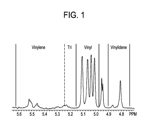
[0015] FIG. 1 graphically depicts the regions for unsaturations.
[0016] FIG. 2 pictorially depicts a flow diagram of reactor stream feed
data flows of an
ethylene/alpha-olefin interpolymer composition according to one or more
embodiments
described herein.
DETAILED DESCRIPTION
[0017] Reference will now be made in detail to embodiments of multilayer
shrink films,
and methods thereof. The multilayer shrink films may be used in the packaging
of multiple
articles. It is noted, however, that this is merely an illustrative
implementation of the
- 4 -
CA 03068960 2020-01-03
WO 2019/010071
PCT/US2018/040169
embodiments disclosed herein. The embodiments are applicable to other
technologies that
are susceptible to similar problems as those discussed above. For example, the
multilayer
shrink films described herein may be used in other flexible packaging
applications, such as,
heavy duty shipping sacks, liners, sacks, stand-up pouches, detergent pouches,
sachets, etc.,
all of which are within the purview of the present embodiments.
[0018] The multilayer shrink films described herein are polyethylene-based
or ethylene-
based. The term "polyethylene-based" or "ethylene-based," are used
interchangeably herein
to mean that the film contains greater than 50 wt.%, at least 60 wt.%, at
least 70 wt.%, at least
75 wt.%, at least 80 wt.%, at least 85 wt.%, at least 90 wt.%, at least 95
wt.%, at least 99
wt.%, at least 100 wt.%, based on the total polymer weight present in the
films, of
polyethylene polymers.
[0019] In embodiments herein, the multilayer shrink films comprise a first
skin layer, at
least one core layer, and a second skin layer. The at least one core layer is
positioned between
the first skin layer and the second skin layer. The first and second skin
layers may be the
same or different, and may have an ABA film structure, where A indicates that
the first and
second skin layers are the same in the composition, or an ABC film structure,
where A and C
indicated that the first and second skin layers are different in composition.
In either
configuration (ABA or ABC), the first and second skin layers may have an equal
thickness,
or alternatively, may have an unequal thickness.
[0020] The multilayer shrink films described herein may have a film
thickness of 20 to
100 microns. All individual values and subranges are included and disclosed
herein. For
example, in some embodiments, the multilayer films described herein may have a
film
thickness ranging from 20 to 95 microns, 20 to 90 microns, 20 to 85 microns,
20 to 80
microns, 20 to 75 microns, from 20 to 72 microns, from 25 to 72 microns, from
25 to 70
microns, or from 30 to 70 microns.
[0021] The first skin layer and the second skin layer may independently
have a thickness
that is from 5-35 percent of the overall thickness of the multilayer shrink
film. In some
embodiments, the first skin layer and the second skin layer may independently
have a
thickness that is from 10-35 percent, 10-30 percent, 15-25 percent, or 20-25
percent of the
overall thickness of the multilayer shrink film. The at least one core layer
has a thickness that
is from 30-90 percent of the overall thickness of the multilayer shrink film.
In some
- 5 -
CA 03068960 2020-01-03
WO 2019/010071
PCT/US2018/040169
embodiments, the at least one core layer has a thickness that is from 40-90
percent, 50-90
percent, 50-85 percent, 50-80 percent, 50-75 percent, 50-70 percent, or 50-65
percent of the
overall thickness of the multilayer shrink film. In other embodiments, the at
least one core
layer has a thickness that is from 55-90 percent, 60-90 percent, 65-90
percent, 70-90 percent,
or 75-90 percent of the overall thickness of the multilayer shrink film.
[0022] The thickness ratio of the first skin layer and the second skin
layer to the at least
one core layer can be any ratio suitable to maintain the optical and
mechanical properties of
a shrink film. In some embodiments, the thickness ratio of the first skin
layer and the second
skin layer to the at least one core layer may be 1:5 to 1:1, 1:4 to 1:1, 1:3
to 1:1, 1:2 to 1:1, or
1:1.5 to 1:1.
[0023] The first skin layer comprises from 25 to 60 wt.%, based on the
total polymer
weight in the first skin layer, of an ethylene/a-olefin interpolymer
composition. All individual
values and subranges described above are included and disclosed herein. For
example, in
some embodiments, the first skin layer may comprise 25 to 55 wt.%, 30 to 55
wt.%, 35 to 55
wt.%, or 40 to 55 wt.% of the ethylene/a-olefin interpolymer composition. In
other
embodiments, the first skin layer may comprise 25 to 50 wt.%, 25 to 45 wt.%,
or 25 to 40
wt.% of the ethylene/a-olefin interpolymer composition.
[0024] The second skin layer comprises from 25 to 60 wt.%, based on the
total polymer
weight in the second skin layer, of an ethylene/a-olefin interpolymer
composition. All
individual values and subranges described above are included and disclosed
herein. For
example, in some embodiments, the second skin layer may comprise 25 to 55
wt.%, 30 to 55
wt.%, 35 to 55 wt.%, or 40 to 55 wt.% of the ethylene/a-olefin interpolymer
composition. In
other embodiments, the second skin layer may comprise 25 to 50 wt.%, 25 to 45
wt.%, or 25
to 40 wt.% of the ethylene/a-olefin interpolymer composition. As previously
described
herein, the first skin layer and the second skin layer may have the same
composition or may
have a different composition, including the same or differing amounts of the
ethylene/a-olefin
interpolymer composition.
[0025] The at least one core layer comprises from 15 to 85 wt.%, based on
the total
polymer weight in the at least one core layer, of an ethylene/a-olefin
interpolymer
composition. All individual values and subranges described above are included
and disclosed
herein. For example, in some embodiments, the at least one core layer may
comprise 25 to
- 6 -
CA 03068960 2020-01-03
WO 2019/010071
PCT/US2018/040169
85 wt.%, 30 to 85 wt.%, 35 to 85 wt.%, 40 to 85 wt.%, or 45 to 85 wt.% of the
ethylene/a-
olefin interpolymer composition. In other embodiments, the at least one core
layer may
comprise 25 to 75 wt.%, 25 to 65 wt.%, or 25 to 50 wt.% of the ethylene/a-
olefin interpolymer
composition.
[0026] The wt.% amount of the ethylene/alpha-olefin interpolymer
composition present
in the first skin layer is different from the wt.% amount of the
ethylene/alpha-olefin
interpolymer composition present in the at least one core layer. Also, the
wt.% amount of the
ethylene/alpha-olefin interpolymer composition present in the second skin
layer is different
from the wt.% amount of the ethylene/alpha-olefin interpolymer composition
present in the
at least one core layer. The multilayer shrink film comprises from 25 wt.% to
75 wt.%, based
on the total weight of polymers present in the multilayer shrink film, of the
ethylene/alpha-
olefin interpolymer composition. All individual values and subranges described
above are
included and disclosed herein. For example, in some embodiments, the wherein
the
multilayer shrink film comprises from 30 wt.% to 75 wt.%, from 35 wt.% to 75
wt.%, or from
40 wt.% to 75 wt.%, based on the total weight of polymers present in the
multilayer shrink
film, of the ethylene/alpha-olefin interpolymer composition. The multilayer
shrink film
further comprises from 30 to 55 wt.%, based on the total weight of polymers
present in the
multilayer shrink film, of a low density polyethylene polymer. All individual
values and
subranges described above are included and disclosed herein. For example, in
some
embodiments, the multilayer shrink film further comprises from 35 to 55 wt.%,
based on the
total weight of polymers present in the multilayer shrink film, of a low
density polyethylene
polymer.
Ethylene/a-Olefin Interpolymer Composition
[0027] The ethylene/a-olefin interpolymer composition comprises (a) less
than or equal
to 100 percent, for example, at least 70 percent, at least 75 percent, at
least 80 percent, at least
85 percent, at least 90 percent, or at least 92 percent, by weight of the
units derived from
ethylene; and (b) less than 30 percent, for example, less than 25 percent,
less than 20 percent,
less than 15 percent, less than 10 percent, or less than 8 percent, by weight
of units derived
from one or more a-olefin comonomers. The term "ethylene/a-olefin interpolymer
composition" refers to a polymer that contains more than 50 mole percent
polymerized
ethylene monomer (based on the total amount of polymerizable monomers) and,
optionally,
may contain at least one comonomer. The comonomer content may be measured
using any
- 7 -
CA 03068960 2020-01-03
WO 2019/010071
PCT/US2018/040169
suitable technique, such as techniques based on nuclear magnetic resonance
("NMR")
spectroscopy, and, for example, by 13C NMR analysis as described in U.S.
Patent 7,498,282,
which is incorporated herein by reference
[0028] The a-olefin comonomers have no more than 20 carbon atoms. For
example, the
a-olefin comonomers may have 3 to 10 carbon atoms, or 3 to 8 carbon atoms.
Exemplary a-
olefin comonomers include, but are not limited to, propylene, 1-butene, 1-
pentene, 1-hexene,
1-heptene, 1-octene, 1-nonene, 1-decene, and 4-methyl- 1 -pentene. The one or
more a-olefin
comonomers may, for example, be selected from the group consisting of
propylene, 1-butene,
1-hexene, and 1-octene; or in the alternative, from the group consisting of 1-
hexene and 1-
octene.
[0029] In embodiments herein, the ethylene/a-olefin interpolymer
composition has a
density in the range of 0.890 to 0.915 g/cc. All individual values and
subranges from 0.890
to 0.915 g/cc are included and disclosed herein. For example, in some
embodiments, the
ethylene/a-olefin interpolymer composition has a density from a lower limit of
0.890, 0.895,
or 0.900 g/cc to an upper limit of 0.915, 0.912, 0.910, 0.908, or 0.905 g/cc.
[0030] In addition to the density, the ethylene/a-olefin interpolymer
composition has a
melt index (I2) in a range of from 0.1 to 5 g/10 minutes. All individual
values and subranges
from 0.1 to 5 g/10 minutes are included and disclosed herein. For example, in
some
embodiments, the ethylene/a-olefin interpolymer composition has a melt index
(I2) ranging
from a lower limit of 0.1, 0.2, 0.5, or 0.8 g/10 minutes to an upper limit of
1.2, 1.5, 1.8, 2.0,
2.2, 2.5, 3.0, 4.0, 4.5 or 5.0 g /10 minutes.
[0031] In addition to the density and melt index (I2), the ethylene/a-
olefin interpolymer
composition has a molecular weight distribution (Man) in the range of from 1.8
to 3.5. All
individual values and subranges from 1.8 to 3.5 are included and disclosed
herein. For
example, in some embodiments, the ethylene/a-olefin interpolymer composition
has a
molecular weight distribution (Kan) ranging from a lower limit of 1.8, 2, 2.1,
or 2.2 to an
upper limit of 2.5, 2.7, 2.9, 3.2, or 3.5.
[0032] In addition to the density, melt index (I2), and molecular weight
distribution
(Mw/Mr,), the ethylene/a-olefin interpolymer composition has a Comonomer
Distribution
Constant (CDC) in the range of from 95 to 200. All individual values and
subranges from 95
- 8 -
CA 03068960 2020-01-03
WO 2019/010071
PCT/US2018/040169
to 200 are included and disclosed herein. For example, in some embodiments,
the ethylene/a-
olefin interpolymer composition has a CDC from 95 to 175, from 95 to 150, or
from 95 to
125.
[0033] In addition to the density, melt index (I2), molecular weight
distribution (Mw/M.),
and the CDC, the ethylene/a-olefin interpolymer composition may have a vinyl
unsaturation
of less than 0.15 vinyls per one thousand carbon atoms present in the
ethylene/a-olefin
interpolymer composition. In addition to the density, melt index (I2),
molecular weight
distribution (Mw/M.), CDC, and vinyl unsaturation, the ethylene/a-olefin
interpolymer
composition may have a zero shear viscosity ratio (ZSVR) in the range of from
2 to 20, for
example, from 2 to 10, from 2 to 6, or from 2.5 to 4.
[0034] In addition to the density, melt index (I2), molecular weight
distribution (Mw/M.),
CDC, vinyl unsaturation, and ZSVR, the ethylene/a-olefin interpolymer
composition may
have a melt index ratio, 110/12, of from 6 to 12. All individual values and
subranges are
included and disclosed herein. For example, the ethylene/a-olefin interpolymer
composition
may have a melt index ratio, 110/12, of from 6 to 11, from 6.5 to 11, from 7
to 11, from 7 to
10, or from 7.5 to 10.
[0035] In addition to the density, melt index (I2), molecular weight
distribution (Mw/M.),
CDC, vinyl unsaturation, ZSVR, and melt index ratio (I1042), the ethylene/a-
olefin
interpolymer composition may have a molecular weight (Mw) in the range of
50,000 to
250,000 g/mole. For example, the molecular weight (Mw) can be from a lower
limit of
50,000, 60,000, 70,000 g/mole to an upper limit of 150,000, 180,000, 200,000
or 250,000
g/mole.
[0036] In addition to the density, melt index (I2), molecular weight
distribution (Mw/M.),
CDC, vinyl unsaturation, ZSVR, melt index ratio (I1042), and Mw, the
ethylene/a-olefin
interpolymer composition may have a molecular weight distribution (Mz/Mw) in
the range
of less than 4, less than 3.75, less than 3.5, less than 3.25, less than 3, or
from 1.8 to 3.8, from
1.8 to 3.5, from 1.8 to 3.3, from 1.8 to 3.0, from 2.0 to 3.0, or from 2.0 to
2.8.
[0037] In addition to the density, melt index (I2), molecular weight
distribution (Mw/M.),
CDC, vinyl unsaturation, ZSVR, melt index ratio (11042), Mw, and the Mz/Mw,
the
ethylene/a-olefin interpolymer composition may have a vicat softening point (
C) of less than
- 9 -
CA 03068960 2020-01-03
WO 2019/010071
PCT/US2018/040169
98 C. All individual values and subranges less than 98 C are included and
disclosed herein.
For example, in some embodiments, the ethylene/a-olefin interpolymer
composition may
have a vicat softening point ( C) of less than 97 C, less than 96 C, or less
than 95.5 C. In
other embodiments, the ethylene/a-olefin interpolymer composition may have a
vicat
softening point ( C) ranging from 70 C to less than 98 C, from 70 C to 97
C, or from 70
C to 96 C.
[0038] In addition to the density, melt index (I2), molecular weight
distribution (Mw/Mr,),
CDC, vinyl unsaturation, ZSVR, melt index ratio (11042), Mw, Mz/Mw, and vicat
softening
point, the ethylene/a-olefin interpolymer composition may have a peak melting
point
temperature ( C) of less than 123 C. All individual values and subranges less
than 123 C
are included and disclosed herein. For example, in some embodiments, the
ethylene/a-olefin
interpolymer composition may have a peak melting point temperature ( C) of
less than 120
C, less than 115 C, less than 110 C, or less than 105 C. In other
embodiments, the
ethylene/a-olefin interpolymer composition may have a peak melting point
temperature ( C)
ranging from 90 C to less than 120 C, from 90 C to 115 C, or from 90 C to
110 C.
[0039] Any conventional ethylene (co)polymerization reaction processes may
be
employed to produce the ethylene/a-olefin interpolymer composition. Such
conventional
ethylene (co)polymerization reaction processes include, but are not limited
to, gas phase
polymerization process, slurry phase polymerization process, solution phase
polymerization
process, and combinations thereof using one or more conventional reactors,
e.g. fluidized bed
gas phase reactors, loop reactors, stirred tank reactors, batch reactors in
parallel, series, and/or
any combinations thereof. Examples of suitable polymerization processes are
described in
U.S. Pat. 6,982, 311, U.S. Pat. 6,486,284, U.S. Pat. 8,829,115 or U. S.
8,327,931, which are
incorporated herein by reference.
Low Density Polyethylene (LDPE)
[0040] The low density polyethylene has a density of from 0.910 g/cc to
0.930 g/cc. All
individual values and subranges are included and disclosed herein. For
example, in some
embodiments, the low density polyethylene may have a density of from 0.912
g/cc to 0.930
g/cc, 0.915 g/cc to 0.930 g/cc, 0.915 g/cc to 0.927 g/cc, 0.917 g/cc to 0.930
g/cc, 0.917 g/cc
to 0.927 g/cc, or 0.919 g/cc to 0.925 g/cc. In addition to the density, the
low density
polyethylene has a melt index, or 12, of from 0.1 g/10 mm to 10 g/10 mm. All
individual
- 10 -
CA 03068960 2020-01-03
WO 2019/010071
PCT/US2018/040169
values and subranges are included and disclosed herein. For example, in some
embodiments,
the low density polyethylene may have a melt index from 0.1 to 7 g/10 min, 0.1
to 5 g/10
mm, 0.1 to 4 g/10 min, 0.1 to 3.5 g/10 mm, 0.1 to 3 g/10 mm, 0.1 g/10 mm to
2.5 g/10 mm,
0.1 g/10 mm to 2 g/10 mm, 0.1 g/10 mm to 1.5 g/10 mm. In other embodiments,
the LDPE
has a melt index from 0.1 g/10 mm to 1.1 g/10 mm. In further embodiments, the
LDPE has
a melt index of 0.1-0.9 g/10 mm.
[0041] In addition to the density and melt index (I2), the low density
polyethylene may
have a melt strength of from 10 cN to 35 cN. All individual values and
subranges are included
and disclosed herein. For example, in some embodiments, the low density
polyethylene may
have a melt strength of from 10 cN to 30 cN, from 10 cN to 28 cN, from 10 cN
to 25 cN,
from 10 cN to 20 cN, or from 10 cN to 18 cN. In other embodiments, the low
density
polyethylene may have a melt strength of from 12 cN to 30 cN, from 15 cN to 30
cN, from
18 cN to 30 cN, from 20 cN to 30 cN, or from 22 cN to 30 cN. In further
embodiments, the
low density polyethylene may have a melt strength of from 12 cN to 28 cN, from
12 cN to 25
cN, from 15 cN to 25 cN, from 15 cN to 23 cN, or from 17 cN to 23 cN.
[0042] In addition to the density, melt index (I2), and melt strength, the
low density
polyethylene may have a molecular weight distribution (MWD or Mw/Mn) of from 5
to 20.
All individual values and subranges are included and disclosed herein. For
example, in some
embodiments, the low density polyethylene may have a MWD of from 5 to 18, from
5 to 15,
from 5 to 12, from 5 to 10, or from 5 to 8. In other embodiments, the low
density polyethylene
may have a MWD of from 8 to 20, from 10 to 20, from 12 to 20, from 15 to 20,
or from 17
to 20. In further embodiments, the low density polyethylene may have a MWD of
from 8 to
18, from 8 to 15, from 10 to 18, or from 10 to 15. The MWD may be measured
according to
the triple detector gel permeation chromatography (TDGPC) test method outlined
below.
[0043] The LDPE may include branched polymers that are partly or entirely
homopolymerized or copolymerized in autoclave and/or tubular reactors, or any
combination
thereof, using any type of reactor or reactor configuration known in the art,
at pressures above
14,500 psi (100 MPa) with the use of free-radical initiators, such as
peroxides (see for
example U.S. Pat. No. 4,599,392, herein incorporated by reference). In some
embodiments,
the LDPE may be made in an autoclave process under single phase conditions
designed to
impart high levels of long chain branching, such as described in PCT patent
publication WO
2005/023912, the disclosure of which is incorporated herein. Examples of
suitable LDPEs
-11 -
CA 03068960 2020-01-03
WO 2019/010071
PCT/US2018/040169
may include, but are not limited to, ethylene homopolymers, and high pressure
copolymers,
including ethylene interpolymerized with, for example, vinyl acetate, ethyl
acrylate, butyl
acrylate, acrylic acid, methacrylic acid, carbon monoxide, or combinations
thereof. The
ethylene may also be interpolymerized with an alpha-olefin comonomer, for
example, at least
one C3-C20 alpha-olefin, such as propylene, isobutylene, 1-butene, 1-pentene,
1-hexene, and
mixtures thereof. Exemplary LDPE resins may include, but are not limited to,
resins sold by
The Dow Chemical Company, such as, LDPE 1321 resins, LDPE 6211 resins, LDPE
6621
resins, or AGILITYTm 1000 and 2001 resins, resins sold by Westlake Chemical
Corporation
(Houston, TX), such as EF412, EF602, EF403, or EF601, resins sold by
LyondellBasell
Industries (Houston, TX), such as, PETROTHENETm M2520 or NA940, and resins
sold by
The ExxonMobil Chemical Company (Houston, TX) such as, LDPE LD 051.LQ or
NEXXSTARTm LDPE-00328. Other exemplary LDPE resins are described in WO
2014/051682 and WO 2011/019563, which are herein incorporated by reference.
Multilayer Shrink Films
[0044] The first skin layer, second skin layer, and/or the at least one
core layer of the
multilayer shrink films described herein may further incorporate optional
polymers and
additives. Exemplary optional polymers may include a medium density
polyethylene
(MDPE), a high density polyethylene (HDPE), or combinations thereof. In some
embodiments, the first skin layer, second skin layer, and/or the at least one
core layer of the
multilayer shrink film may comprise from 0.5 to 30%, by weight of the polymer
composition,
of MDPE. All individual values and subranges from 0.5 to 30% are included and
disclosed
herein. For example, in some embodiments, the first skin layer, second skin
layer, and/or the
at least one core layer of the multilayer shrink film may comprise from 1 to
30%, 1 to 20%,
1 to 15%, 1 to 10%, by weight of the polymer composition, of MDPE. In further
embodiments, the first skin layer, second skin layer, and/or the at least one
core layer of the
multilayer shrink film may further comprise from 5 to 10%, by weight of the
polymer
composition, of MDPE.
[0045] In some embodiments, the first skin layer, second skin layer, and/or
the at least
one core layer of the multilayer shrink film may comprise from 0.5 to 30%, by
weight of the
polymer composition, of HDPE. All individual values and subranges from 0.5 to
30% are
included and disclosed herein. For example, in some embodiments, the first
skin layer,
second skin layer, and/or the at least one core layer of the multilayer shrink
film may comprise
- 12 -
CA 03068960 2020-01-03
WO 2019/010071
PCT/US2018/040169
from 1 to 30%, 1 to 20%, 1 to 15%, 1 to 10%, by weight of the polymer
composition, of
HDPE. In further embodiments, the first skin layer, second skin layer, and/or
the at least one
core layer of the multilayer shrink film may further comprise from 5 to 10%,
by weight of the
polymer composition, of HDPE.
[0046] Exemplary additives may include, but are not limited to, antistatic
agents, color
enhancers, dyes, lubricants, fillers such as TiO2 or CaCO3, opacifiers,
nucleators, processing
aids, pigments, primary antioxidants, secondary antioxidants, processing aids,
UV stabilizers,
anti-blocks, slip agents, tackifiers, fire retardants, anti-microbial agents,
odor reducer agents,
antifungal agents, and combinations thereof. The multilayer shrink film may
contain from
about 0.1 to about 10 percent by the combined weight of such additives, based
on the total
weight of materials present in the multilayer shrink film. In some
embodiments, the
multilayer shrink films described herein further comprise one or more
additives selected from
the group consisting of antiblocking agents, processing aids, slip agents,
colors or pigments,
and fillers.
[0047] In some embodiments, the multilayer shrink films described herein
may exhibit a
CD shrinkage higher than 4% at 120 C, according to ASTM D2732 or a CD
shrinkage higher
than 6% at 120 C, according to ASTM D2732.
[0048] The multilayer films described herein can be made by a variety of
techniques, such
as, blown film techniques. Methods of making multilayer blown films are
described in U.S.
Patent No. 6,521,338 (Maka), the entirety of which patent is incorporated
herein by reference.
For example, in some embodiments, a multilayer shrink film can be made by co-
extruding a
first skin layer composition, second skin layer composition, and at least one
core layer
composition in an extruder to form a tube having a first skin layer formed
from the first skin
layer composition, second skin layer formed from the second skin layer
composition, and at
least one core layer formed from the at least one core layer composition; and
cooling the tube
to form a multilayer shrink film.
[0049] The first skin layer composition comprises from 25 to 60 wt.%, based
on the total
polymer weight in the first skin layer, of an ethylene/a-olefin interpolymer
composition
having a density in the range of from 0.890 g/cc to 0.915 g/cc, a melt index
(I2) in a range of
from 0.1 to 5 g/ 10 minutes, a molecular weight distribution (Kan) in the
range of from 1.8
to 3.5, and a Comonomer Distribution Constant (CDC) in the range of from 95 to
200; the
- 13 -
CA 03068960 2020-01-03
WO 2019/010071
PCT/US2018/040169
second skin layer composition comprises from 25 to 60 wt.%, based on the total
polymer
weight in the second skin layer, of an ethylene/a-olefin interpolymer
composition having a
density in the range of from 0.890 g/cc to 0.915 g/cc, a melt index (I2) in a
range of from 0.1
to 5 g/ 10 minutes, a molecular weight distribution (Man) in the range of from
1.8 to 3.5,
and a Comonomer Distribution Constant (CDC) in the range of from 95 to 200;
and the at
least one core layer composition comprises from 15 to 85 wt.%, based on the
total polymer
weight in the at least one core layer, of an ethylene/a-olefin interpolymer
composition having
a density in the range of from 0.890 g/cc to 0.915 g/cc, a melt index (I2) in
a range of from
0.1 to 5 g/ 10 minutes, a molecular weight distribution (Man) in the range of
from 1.8 to
3.5, and a Comonomer Distribution Constant (CDC) in the range of from 95 to
200; wherein
the at least one core layer is positioned between the first skin layer and the
second skin layer;
wherein the wt.% amount of the ethylene/alpha-olefin interpolymer composition
present in
the first skin layer is different from the wt.% amount of the ethylene/alpha-
olefin interpolymer
composition present in the core layer, and the wt.% amount of the
ethylene/alpha-olefin
interpolymer composition present in the second skin layer is different from
the wt.% amount
of the ethylene/alpha-olefin interpolymer composition present in the core
layer; wherein the
multilayer shrink film comprises from 25 wt.% to 75 wt.%, based on the total
weight of
polymers present in the multilayer shrink film, of the ethylene/alpha-olefin
interpolymer
composition; and wherein the multilayer shrink film further comprises from 30
to 55 wt.%,
based on the total weight of polymers present in the multilayer shrink film,
of a low density
polyethylene polymer having a density from 0.910 to 0.930 g/cc and an 12 from
0.1 to 10 g/10
mm.
TEST METHODS
[0050] Unless otherwise stated, the following test methods are used.
Density
[0051] Density can be measured in accordance with ASTM D-792.
Melt Index
[0052] Melt index (I2) can be measured in accordance with ASTM D-1238,
Procedure B
(condition 190 C/2.16 kg). Melt index (ho) can be measured in accordance with
ASTM D-
1238, Procedure B (condition 190 C/10.0 kg).
- 14 -
CA 03068960 2020-01-03
WO 2019/010071
PCT/US2018/040169
Vicat Softening Point
[0053] Vicat softening point may be measured in accordance with ASTM D-
1525.
Gel Permeation Chromatography (GPC)
[0054] The chromatographic system consisted of a PolymerChar GPC-IR
(Valencia,
Spain) high temperature GPC chromatograph equipped with an internal IRS
detector. The
autosampler oven compartment was set at 160 Celsius and the column
compartment was set
at 150 Celsius. The columns used were 3 Agilent "Mixed B" 30cm 10-micron
linear mixed-
bed columns and a 10-um pre-column. The chromatographic solvent used was 1,2,4
trichlorobenzene and contained 200 ppm of butylated hydroxytoluene (BHT). The
solvent
source was nitrogen sparged. The injection volume used was 200 microliters and
the flow
rate was 1.0 milliliters/minute.
[0055] Calibration of the GPC column set was performed with 21 narrow
molecular
weight distribution polystyrene standards with molecular weights ranging from
580 to
8,400,000 and were arranged in 6 "cocktail" mixtures with at least a decade of
separation
between individual molecular weights. The standards were purchased from
Agilent
Technologies. The polystyrene standards were prepared at 0.025 grams in 50
milliliters of
solvent for molecular weights equal to or greater than 1,000,000, and 0.05
grams in 50
milliliters of solvent for molecular weights less than 1,000,000. The
polystyrene standards
were dissolved at 80 degrees Celsius with gentle agitation for 30 minutes. The
polystyrene
standard peak molecular weights were converted to polyethylene molecular
weights using
Equation 1 (as described in Williams and Ward, J. Polym. Sci., Polym. Let., 6,
621 (1968)).:
Mpolyethylene = A x 114
(--polystyrene)B (EQ1)
where M is the molecular weight, A has a value of 0.4315 and B is equal to
1Ø
[0056] A fifth order polynomial was used to fit the respective polyethylene-
equivalent
calibration points. A small adjustment to A (from approximately 0.415 to 0.44)
was made to
correct for column resolution and band-broadening effects such that NIST
standard NBS 1475
is obtained at 52,000 Mw.
- 15 -
CA 03068960 2020-01-03
WO 2019/010071
PCT/US2018/040169
[0057] The total plate count of the GPC column set was performed with
Eicosane
(prepared at 0.04 g in 50 milliliters of TCB and dissolved for 20 minutes with
gentle
agitation.) The plate count (Equation 2) and symmetry (Equation 3) were
measured on a 200
microliter injection according to the following equations:
Max 2
eak
Plate Count = 5.54 * RVP . (EQ2)
Peak Width at -2height)
where RV is the retention volume in milliliters, the peak width is in
milliliters, the peak max
is the maximum height of the peak, and 1/2 height is 1/2 height of the peak
maximum.
(Rear Peak RV one tenth height¨ RI Peak max)
Symmetry ¨ , (EQ3)
01/Peak max¨Front Peak RV one tenth height)
where RV is the retention volume in milliliters and the peak width is in
milliliters, Peak max
is the maximum position of the peak, one tenth height is 1/10 height of the
peak maximum,
rear peak refers to the peak tail at later retention volumes than the peak
max, and front peak
refers to the peak front at earlier retention volumes than the peak max. The
plate count for
the chromatographic system should be greater than 24,000 and symmetry should
be between
0.98 and 1.22.
[0058] Samples were prepared in a semi-automatic manner with the
PolymerChar
"Instrument Control" Software, wherein the samples were weight-targeted at 2
mg/ml, and
the solvent (contained 200ppm BHT) was added to a pre- nitrogen-sparged septa-
capped vial,
via the PolymerChar high temperature autosampler. The samples were dissolved
for 2 hours
at 160 Celsius under "low speed" shaking.
[0059] The calculations of Mn, Mw, and Mz were based on GPC results using
the internal
IRS detector (measurement channel) of the PolymerChar GPC-IR chromatograph
according
to Equations 4-6, using PolymerChar GPCOneTM software, the baseline-subtracted
IR
chromatogram at each equally-spaced data collection point (i), and the
polyethylene
equivalent molecular weight obtained from the narrow standard calibration
curve for the point
(i) from Equation 1.
- 16 -
CA 03068960 2020-01-03
WO 2019/010071 PCT/US2018/040169
IRi
M.= _____________
( (EQ 4)
IRi
polyethylene i )
i
IURi* M polyethylene i)
= ___________________________________ (EQ 5)
IRi
i
1VRi* M polyethylene i2)
Mz = ______________
(EQ 6)
/ * M polyethylenei)
[0060] In order to monitor the deviations over time, a flowrate marker
(decane) was
introduced into each sample via a micropump controlled with the PolymerChar
GPC-IR
system. This flowrate marker was used to linearly correct the flowrate for
each sample by
alignment of the respective decane peak within the sample to that of the
decane peak within
the narrow standards calibration. Any changes in the time of the decane marker
peak are then
assumed to be related to a linear shift in both flowrate and chromatographic
slope. To
facilitate the highest accuracy of a RV measurement of the flow marker peak, a
least-squares
fitting routine is used to fit the peak of the flow marker concentration
chromatogram to a
quadratic equation. The first derivative of the quadratic equation is then
used to solve for the
true peak position. After calibrating the system based on a flow marker peak,
the effective
flowrate (as a measurement of the calibration slope) is calculated as Equation
7. Processing
of the flow marker peak was done via the PolymerChar GPCOneTM Software.
FlowMarker calibration
Flowratee f f ective = Flowrate nominal X (EQ7)
FlowMarker observed
Comonomer Distribution Constant (CDC) Method
[0061] Comonomer distribution constant (CDC) is calculated from comonomer
distribution profile by CEF. CDC is defined as Comonomer Distribution Index
divided by
- 17 -
CA 03068960 2020-01-03
WO 2019/010071
PCT/US2018/040169
Comonomer Distribution Shape Factor multiplying by 100 as shown in the
following
equation:
Comonomer Distribution Index Comonomer
Distribution Index
CDC = _____________________________________________________________ x 100
Comonomer Distribution Shape Factor= __________________________
Half Width/Stdev
wherein Comonomer distribution index stands for the total weight fraction of
polymer chains
with the comonomer content ranging from 0.5 of median comonomer content
(Cmedian) and
1.5 of Cmedian from 35.0 to 119.0 C. Comonomer Distribution Shape Factor is
defined as a
ratio of the half width of comonomer distribution profile divided by the
standard deviation of
comonomer distribution profile from the peak temperature (Tp).
[0062] CDC is calculated according to the following steps:
[0063] (A) Obtain a weight fraction at each temperature (7) (wT(T)) from
35.0 C to
119.0 C with a temperature step increase of 0.200 C from CEF according to
the following
Equation:
119.0
J wT(T)dT = 1
35.0
[0064] (B) Calculate the median temperature (Tmedian) at cumulative weight
fraction of
0.500, according to the following Equation:
IT median
J wT(T)dT = 0.5
35.0
[0065] (C) Calculate the corresponding median comonomer content in mole %
(Cmedian)
at the median temperature (Tn,edian) by using comonomer content calibration
curve according
to the following Equation:
2 07.2 6
ln(1 ¨ comonomer content) =
273.12 + T + 0.5533
R2 = 0.997
- 18 -
CA 03068960 2020-01-03
WO 2019/010071
PCT/US2018/040169
[0066] (D) Construct a comonomer content calibration curve by using a
series of
reference materials with known amount of comonomer content, i.e., eleven
reference
materials with narrow comonomer distribution (mono-modal comonomer
distribution in CEF
from 35.0 to 119.0 C) with weight average Mw of 35,000 to 115,000 (measured
via
conventional GPC) at a comonomer content ranging from 0.0 mole% to 7.0 mole%
are
analyzed with CEF at the same experimental conditions specified in CEF
experimental
sections;
[0067] (E) Calculate comonomer content calibration by using the peak
temperature (Tp)
of each reference material and its comonomer content; The calibration is
calculated from each
reference material according to the following Equation:
2 07.2 6
ln(1 ¨ comonomer content) ¨
273.12 + T + 0.5533
R2 = 0.997
wherein: R2 is the correlation constant;
[0068] (F) Calculate Comonomer Distribution Index from the total weight
fraction with
a comonomer content ranging from 0.5*Cmedian to 1.5* Cmedian, and if Tmedian
is higher than
98.0 C, Comonomer Distribution Index is defined as 0.95;
[0069] (G) Obtain Maximum peak height from CEF comonomer distribution profile
by
searching each data point for the highest peak from 35.0 C to 119.0 C (if
the two peaks are
identical, then the lower temperature peak is selected); half width is defined
as the
temperature difference between the front temperature and the rear temperature
at the half of
the maximum peak height, the front temperature at the half of the maximum peak
is searched
forward from 35.0 C, while the rear temperature at the half of the maximum
peak is searched
backward from 119.0 C, in the case of a well-defined bimodal distribution
where the
difference in the peak temperatures is equal to or greater than the 1.1 times
of the sum of half
width of each peak, the half width of the inventive ethylene-based polymer
composition is
calculated as the arithmetic average of the half width of each peak;
[0070] (H) Calculate the standard deviation of temperature (Stdev)
according the
following Equation:
- 19 -
CA 03068960 2020-01-03
WO 2019/010071
PCT/US2018/040169
j119.0
Stdev = 1(T ¨ Tp)2
35.0
[0071] An example of a comonomer distribution profile is shown in FIG. 23 of
EP
2571690, which is incorporated herein by reference.
Differential Scanning Calorimetry (DSC)
[0072] Differential Scanning Calorimetry (DSC) is used to measure the
melting and
crystallization behavior of a polymer over a wide range of temperatures. For
example, the
TA Instruments Q1000 DSC, equipped with an RCS (refrigerated cooling system)
and an
autosampler is used to perform this analysis. During testing, a nitrogen purge
gas flow of 50
ml/minis used. Each sample is melt pressed into a thin film at about 175 C;
the melted sample
is then air-cooled to room temperature (approx. 25 C). The film sample is
formed by pressing
a "0.1 to 0.2 gram" sample at 175 C at 1,500 psi, and 30 seconds, to form a
"0.1 to 0.2 mil
thick" film. A 3-10 mg, 6 mm diameter specimen is extracted from the cooled
polymer,
weighed, placed in a light aluminum pan (ca 50 mg), and crimped shut. Analysis
is then
performed to determine its thermal properties. The thermal behavior of the
sample is
determined by ramping the sample temperature up and down to create a heat flow
versus
temperature profile. First, the sample is rapidly heated to 180 C, and held
isothermal for five
minutes, in order to remove its thermal history. Next, the sample is cooled to
-40 C, at a 10
C/minute cooling rate, and held isothermal at -40 C for five minutes. The
sample is then
heated to 150 C (this is the "second heat" ramp) at a 10 C/minute heating
rate. The cooling
and second heating curves are recorded. The cool curve is analyzed by setting
baseline
endpoints from the beginning of crystallization to -20 C. The heat curve is
analyzed by
setting baseline endpoints from -20 C to the end of melt. The values
determined are peak
melting temperature (Tm), peak crystallization temperature (Tc), heat of
fusion (Hf) (in
Joules per gram), and the calculated % crystallinity for polyethylene samples
using: %
Crystallinity = ((Hf)/(292 J/g)) x 100. The heat of fusion (Hf) and the peak
melting
temperature are reported from the second heat curve. Peak crystallization
temperature is
determined from the cooling curve.
-20 -
CA 03068960 2020-01-03
WO 2019/010071
PCT/US2018/040169
Melt Strength
[0073] Melt
strength may be measured at 190 C using a Goettfert Rheotens 71.97
(Goettfert Inc.; Rock Hill, SC), melt fed with a Goettfert Rheotester 2000
capillary rheometer
equipped with a flat entrance angle (180 degrees) of length of 30 mm and
diameter of 2.0
mm. The pellets (20-30 gram pellets) are fed into the barrel (length = 300 mm,
diameter =
12 mm), compressed and allowed to melt for 10 minutes before being extruded at
a constant
piston speed of 0.265 mm/s, which corresponds to a wall shear rate of 38.2 s-1
at the given die
diameter. The extrudate passes through the wheels of the Rheotens located 100
mm below
the die exit and is pulled by the wheels downward at an acceleration rate of
2.4 mm/s2. The
force (in cN) exerted on the wheels is recorded as a function of the velocity
of the wheels (in
mm/s). Melt strength is reported as the plateau force (cN) before the strand
broke.
Creep Zero Shear Viscosity Measurement Method
[0074] Zero-
shear viscosities are obtained via creep tests that were conducted on an AR-
G2 stress controlled rheometer (TA Instruments; New Castle, Del) using 25-mm-
diameter
parallel plates at 190 C. The rheometer oven is set to test temperature for
at least 30 minutes
prior to zeroing fixtures. At the testing temperature a compression molded
sample disk is
inserted between the plates and allowed to come to equilibrium for 5 minutes.
The upper
plate is then lowered down to 50 wn above the desired testing gap (1.5 mm).
Any superfluous
material is trimmed off and the upper plate is lowered to the desired gap.
Measurements are
done under nitrogen purging at a flow rate of 5 L/min. Default creep time is
set for 2 hours.
[0075] A
constant low shear stress of 20 Pa is applied for all of the samples to ensure
that the steady state shear rate is low enough to be in the Newtonian region.
The resulting
steady state shear rates are in the range of 10-3 to 10-4 s-1 for the samples
in this study. Steady
state is determined by taking a linear regression for all the data in the last
10% time window
of the plot of log (J(t)) vs. log(t), where J(t) is creep compliance and t is
creep time. If the
slope of the linear regression is greater than 0.97, steady state is
considered to be reached,
then the creep test is stopped. In all cases in this study the slope meets the
criterion within 2
hours. The steady state shear rate is determined from the slope of the linear
regression of all
of the data points in the last 10% time window of the plot of c VS. t, where c
is strain. The
zero-shear viscosity is determined from the ratio of the applied stress to the
steady state shear
rate.
-21-
CA 03068960 2020-01-03
WO 2019/010071
PCT/US2018/040169
[0076] In
order to determine if the sample is degraded during the creep test, a small
amplitude oscillatory shear test is conducted before and after the creep test
on the same
specimen from 0.1 to 100 rad/s. The complex viscosity values of the two tests
are compared.
If the difference of the viscosity values at 0.1 rad/s is greater than 5%, the
sample is considered
to have degraded during the creep test, and the result is discarded.
[0077] Zero-
Shear Viscosity Ratio (ZSVR) is defined as the ratio of the zero-shear
viscosity (ZSV) of the branched polyethylene material to the ZSV of the linear
polyethylene
material at the equivalent weight average molecular weight (Mw-gpc) according
to the
following Equation:
17os ZSVR = ¨= 17os
17oL 2.29 x 10⁻¹⁵/41 pc
[0078] The ZSV
value is obtained from creep test at 190 C via the method described
above. The Mw-gpc value is determined by the conventional GPC method. The
correlation
between ZSV of linear polyethylene and its Mw-gpc was established based on a
series of
linear polyethylene reference materials. A description for the ZSV-Mw
relationship can be
found in the ANTEC proceeding: Kari ala, Teresa P.; Sammler, Robert L.;
Mangnus, Marc
A.; Hazlitt, Lonnie G.; Johnson, Mark S.; Hagen, Charles M., Jr.; Huang, Joe
W. L.; Reichek,
Kenneth N. Detection of low levels of long-chain branching in polyolefins.
Annual
Technical Conference - Society of Plastics Engineers (2008), 66th 887-891.
1H NMR Method
[0079] 3.26 g
of stock solution is added to 0.133 g of polyolefin sample in 10 mm NMR
tube. The stock solution is a mixture of tetrachloroethane-d2 (TCE) and
perchloroethylene
(50:50, w:w) with 0.001M Cr'. The solution in the tube is purged with N2 for 5
minutes to
reduce the amount of oxygen. The capped sample tube is left at room
temperature overnight
to swell the polymer sample. The samples are dissolved at 115 C with shaking.
The samples
are free of the additives that may contribute to unsaturation, e.g. slip
agents such as
eruc amide.
[0080] The 1H NMR is run with a 10 mm cryoprobe at 120 C on Bruker AVANCE 400
MHz spectrometer. Two experiments are run to get the unsaturation: the control
and the
double pre-saturation experiments.
-22 -
CA 03068960 2020-01-03
WO 2019/010071
PCT/US2018/040169
[0081] For the control experiment, the data is processed with exponential
window function
with LB=1 Hz, baseline was corrected from 7 to -2 ppm. The signal from
residual 1H of TCE
is set to 100, the integral 'total from -0.5 to 3 ppm is used as the signal
from whole polymer in
the control experiment. The number of CH2 group, NCH2, in the polymer is
calculated as
following:
NCH2=Itota1/2
[0082] For the double presaturation experiment, the data is processed with
exponential
window function with LB=1 Hz, baseline was corrected from 6.6 to 4.5 ppm. The
signal
from residual 1H of TCE is set to 100, the corresponding integrals for
unsaturations (Ivinylene,
Iirisubstituted, 'vinyl and Ivinylidene) were integrated based on the region
shown in FIG. 1.
[0083] The number of unsaturation unit for vinylene, trisubstituted, vinyl
and vinylidene
are calculated:
Nvinylene=Ivinylene/2
Ntrisubstituted=Itrisubstitute
Nviny1=Iviny1/2
Nvinylidene=Ivinylidene/2
[0084] The unsaturation unit/1,000,000 carbons is calculated as following:
Nvinylene/1,000,000C = (Nvinyiene/NCH2)*1,000,000
Ntrisubstitutec1/1,000,000C = (Ntrisubstitutecl/NCH2)*1,000,000
Nviny1/1,000,000C = (Nvinyl/NCH2)*1,000,000
Nvinylidene/1,000,000C = (Nvinylidene/NCH2)*1,000,000
[0085] The requirement for unsaturation NMR analysis includes: level of
quantitation is
0.47 0.02/1,000,000 carbons for Vd2 with 200 scans (less than 1 hour data
acquisition
including time to run the control experiment) with 3.9 wt.% of sample (for Vd2
structure, see
Macromolecules, vol. 38, 6988, 2005), 10 mm high temperature cryoprobe. The
level of
quantitation is defined as signal to noise ratio of 10.
-23 -
CA 03068960 2020-01-03
WO 2019/010071
PCT/US2018/040169
[0086] The chemical shift reference is set at 6.0 ppm for the 1H signal
from residual proton
from TCT-d2. The control is run with ZG pulse, TD 32768, NS 4, DS 12, SWH
10,000 Hz,
AQ 1.64s, D1 14s. The double presaturation experiment is run with a modified
pulse
sequence, 01P 1.354 ppm, 02P 0.960 ppm, PL9 57db, PL21 70 db, TD 32768, NS
200, DS
4, SWH 10,000 Hz, AQ 1.64s, D1 1 s, D13 13s. The modified pulse sequences for
unsaturation with Bruker AVANCE 400 MHz spectrometer are shown below:
;lclpif2_zz
prosol relations=<lcnmr>
#include <Avance.incl>
"d12=20u"
"d11,4u"
1 ze
d12 p12112
2 30m
d13
d12 pl9:f1
dl cw:fl ph29 cw:f2 ph29
dl 1 do:fl do.f2
d12 pll:fl
pl phi
go=2 ph31
30m mc #0 to 2 FO(zd)
exit
ph1=0 2 2 0 1 331
ph29=0
ph31=0 2 2 0 1 3 3 1
Tensile Properties
[0087] Tensile properties, including yield tensile strength, young's
modulus, 2% secant
modulus, ultimate tensile streng,t1n, and ultimate elongation are determined
in the machine and
cross directions according to ASTM D882 using an instron Universal Tester.
Tear Strength
[0088] Tear strength is measured according to ASTM D-1922.
-24 -
CA 03068960 2020-01-03
WO 2019/010071 PCT/US2018/040169
Shrink at 120 C & 130 C
[0089] Shrink at 120 C and 130 C is measured in the machine direction and
cross
direction according to ASTM D-2732.
Examples
[0090] The resins used in the films are shown below in Table 1. Additives
used include
a polymer processing aid ("PPA"), AMPACETTm 102823 BA; a slip agent ("Slip"),
AMPACETTm 901021 BX; and an antiblock agent ("AB"), AMPACETTm 901300 BX.
[0091] Table 1 ¨ Resins
ELITE Dow Dow
AT
AFFINITY"" Inv. LLDPE DOWLEXTM ATTANETm Tm LDPE
PL 1888G Resin 1 2050B 4203G
6101 1613.11 132i
Density
0.905 0.904 0.905 0.923 0.950 0.905 0.921
(g/cc)
Melt
Index, 12
0.8 1.0 0.5 1.3 0.95 0.8 0.25
(g/10
min)
110/12 8 9.5 8.4 8.2 8.7
Mw
106430 91980 118060 132180
(g/mole)
Mn
38630 35720 35660 26910
(g/mole)
Mw/Mn
2.755 2.575 3.310 4.912
(MWD)
Vicat
Softening 95
85 96 98 96
Point
( C)
Peak
Melting
Point 101 98 102 123 110
Temp.
( C)
CDC 107.4 68.9 113.8 88.3
[0092] All resins, except for inventive resin 1, are commercially available
from The Dow
Chemical Company (Midland, MI).
-25 -
CA 03068960 2020-01-03
WO 2019/010071
PCT/US2018/040169
[0093] Inventive Resin 1 may be made as follows: all raw materials (monomer
and
comonomer) and the process solvent (a narrow boiling range high-purity
isoparaffinic
solvent, Isopar-E) are purified with molecular sieves before introduction into
the reaction
environment. Hydrogen is supplied pressurized as a high purity grade and is
not further
purified. The reactor monomer feed stream is pressurized via a mechanical
compressor to
above reaction pressure. The solvent and comonomer feed is pressurized via a
pump to above
reaction pressure. The individual catalyst components are manually batch
diluted with
purified solvent and pressured to above reaction pressure. All reaction feed
flows are
measured with mass flow meters and independently controlled with computer
automated
valve control systems.
[0094] A two reactor system may be used in a series configuration. Each
continuous
solution polymerization reactor consists of a liquid full, non-adiabatic,
isothermal,
circulating, loop reactor which mimics a continuously stirred tank reactor
(CSTR) with heat
removal. Independent control of all fresh solvent, monomer, comonomer,
hydrogen, and
catalyst component feeds is possible. The total fresh feed stream to each
reactor (solvent,
monomer, comonomer, and hydrogen) is temperature controlled to maintain a
single solution
phase by passing the feed stream through a heat exchanger. The total fresh
feed to each
polymerization reactor is injected into the reactor at two locations with
approximately equal
reactor volumes between each injection location. The fresh feed is controlled
with each
injector receiving half of the total fresh feed mass flow. The catalyst
components are injected
into each polymerization reactor through specially designed injection
stingers. The primary
catalyst component feed is computer controlled to maintain each reactor
monomer conversion
at the specified targets. The cocatalyst components are fed based on
calculated specified
molar ratios to the primary catalyst component. Immediately following each
reactor feed
injection location, the feed streams are mixed with the circulating
polymerization reactor
contents with static mixing elements. The contents of each reactor are
continuously circulated
through heat exchangers responsible for removing much of the heat of reaction
and with the
temperature of the coolant side responsible for maintaining an isothermal
reaction
environment at the specified temperature. Circulation around each reactor loop
is provided
by a pump.
-26 -
CA 03068960 2020-01-03
WO 2019/010071
PCT/US2018/040169
[0095] The effluent from the first polymerization reactor (containing
solvent, monomer,
comonomer, hydrogen, catalyst components, and polymer) exits the first reactor
loop and is
added to the second reactor loop.
[0096] The final reactor effluent (second reactor effluent for dual series
configuration)
enters a zone where it is deactivated with the addition of and reaction with a
suitable reagent
(water). At this same reactor exit location other additives are added for
polymer stabilization
(e.g., antioxidants suitable for stabilization during extrusion and blown film
fabrication).
[0097] Following catalyst deactivation and additive addition, the reactor
effluent enters a
devolatization system where the polymer is removed from the non-polymer
stream. The
isolated polymer melt is pelletized and collected. The non-polymer stream
passes through
various pieces of equipment which separate most of the ethylene which is
removed from the
system. Most of the solvent and unreacted comonomer is recycled back to the
reactor system
after passing through a purification system. A small amount of solvent and
comonomer is
purged from the process.
[0098] The reactor stream feed data flows that correspond to the values in
Table 2, which
may be used to produce inventive resin 1, are graphically described in FIG.2.
The data is
presented such that the complexity of the solvent recycle system is accounted
for and the
reaction system can be treated more simply as a once through flow diagram.
-27 -
CA 03068960 2020-01-03
WO 2019/010071
PCT/US2018/040169
[0099] Table 2
Inventive Resin 1
Reactor Configuration Type Dual
Series
Comonomer type Type 1-octene
First Reactor Feed Solvent / Ethylene Mass Flow Ratio g/g 5.3
First Reactor Feed Comonomer / Ethylene Mass Flow Ratio g/g
0.65
First Reactor Feed Hydrogen / Ethylene Mass Flow Ratio g/g 2.0E-04
First Reactor Temperature C 141
First Reactor Pressure barg 50
First Reactor Ethylene Conversion 79.2
Catalyst
First Reactor Catalyst Type Type
component 1
First Reactor Co-Catalyst 1 Type Type Co-
Catalyst 1
First Reactor Co-Catalyst 2 Type Type Co-
Catalyst 2
First Reactor Co-Catalyst 1 to Catalyst Molar Ratio (B to Zr
ratio) Ratio 2.0
First Reactor Co-Catalyst 2 to Catalyst Molar Ratio (Al to Zr
ratio) Ratio 74.1
First Reactor Residence Time min 17.2
Second Reactor Feed Solvent / Ethylene Mass Flow Ratio g/g 2.5
Second Reactor Feed Comonomer / Ethylene Mass Flow Ratio g/g
0.186
Second Reactor Feed Hydrogen / Ethylene Mass Flow Ratio g/g 3.0E-
04
Second Reactor Temperature C 190
Second Reactor Pressure barg 50
Second Reactor Ethylene Conversion 85.9
Catalyst
Second Reactor Catalyst Type Type
component 1
Second Reactor Co-Catalyst 1 Type Type Co-
Catalyst 1
Second Reactor Co-Catalyst 2 Type Type Co-
Catalyst 2
Second Reactor Co-Catalyst 1 to Catalyst Molar Ratio (B to Zr
ratio) mol/mol 1.4
Second Reactor Co-Catalyst 2 to Catalyst Molar Ratio (Al to Zr
ratio) mol/mol 7.0
Second Reactor Residence Time min 7.3
-28 -
CA 03068960 2020-01-03
WO 2019/010071 PCT/US2018/040169
[0100] Table 3
Catalyst component 1
Zirconium,dimethyll[2,2-l1,3-propanediylbis(oxy-KO)lbis113",5,5"-
tris(1,1-dimethylethyl)-5'-methyll1,1':3',1"-terpheny11-2'-olato-K011(2-
)1-
Co-catalyst 1 Amines, bis(hydrogenated tallow
alkyl)methyl,tetrakts(pentafluorophenyl)borate(1-)
Co-catalyst 2 modified methyl aluminoxane
[0101] Table 4 ¨ Film Formulations
Layers formulation
At Least One Second Skin Overall Film
Samples First Skin Layer
"A" (25%) Core Layer Layer "A" Formulation
"B" (50%) (25%)
Comparative 100% ELITE 100% ELITE 100% ELITE 100%
ELITE
Film 1 ATTm 6101 ATTm 6101 ATTm
6101 ATTm 6101
55% LDPE 1321
50% LDPE 1321
60% LDPE 1321 60% LDPE 1321
25% ELITE
Comparative
49% ELITE ATTm
6101 +
Film 2 40% LLDPE 40% LLDPE
ATTm 6101 + 20% LLDPE
1613.11 1613.11
1% PPA
1613.11+
0.5% PPA
55% LDPE 1321
50% LDPE 1321
60% LDPE 1321 60% LDPE 1321
25% AFFINITY
Comparative
49% AFFINITY PLTM 1888G +
Film 3 40% LLDPE 40% LLDPE
PLTM 1888G + 20% LLDPE
1613.11 1613.11
1% PPA
1613.11+
0.5% PPA
55% LDPE 1321
50% LDPE 1321
60% LDPE 1321 60% LDPE 1321
25% ATTANETm
Comparative
49% ATTANETm 4203G +
Film 4 40% LLDPE 40% LLDPE
4203G + 20%
LLDPE
1613.11 1613.11
1% PPA
1613.11+
0.5% PPA
50% LDPE 1321 55% LDPE 1321
60% LDPE 1321 60% LDPE 1321
25% LLDPE 32.5% LLDPE
Comparative
1613.11+
1613.11+
Film 5 40% LLDPE 40% LLDPE
25% 12.5%
1613.11 1613.11
DOWLEXTM DOWLEXTM
2050B 2050B
-29 -
CA 03068960 2020-01-03
WO 2019/010071 PCT/US2018/040169
60% LDPE 1321 60%
LDPE 1321 55% LDPE 1321
+ 50% LDPE 1321 + +
33% ELITE + 33% ELITE 41% ELITE
Inventive Film
ATTm 6101 + 49% ELITE ATTm 6101 + ATTm
6101 +
1
5% AB + ATTm 6101 + 5% AB + 2.5% AB +
1% PPA + 1% PPA 1% PPA + 1% PPA +
1% Slip 1% Slip 0.5% Slip
50% LDPE 1321 50%
LDPE 1321 45% LDPE 1321
+ 40% LDPE 1321 + +
43% ELITE + 43% ELITE 51% ELITE
Inventive Film
ATTm 6101 + 59% ELITE ATTm 6101 + ATTm
6101 +
2
5% AB + ATTm 6101 + 5% AB + 2.5% AB +
1% PPA + 1% PPA 1% PPA + 1% PPA +
1% Slip 1% Slip 0.5% Slip
40% LDPE 1321 40%
LDPE 1321 35% LDPE 1321
+ 30% LDPE 1321 + +
53% ELITE + 53% ELITE 61% ELITE
Inventive Film
ATTm 6101 + 69% ELITE ATTm 6101 + ATTm
6101 +
3
5% AB + ATTm 6101 + 5% AB + 2.5% AB +
1% PPA + 1% PPA 1% PPA + 1% PPA +
1% Slip 1% Slip 0.5% Slip
60% LDPE 1321 60%
LDPE 1321 55% LDPE 1321
+ 50% LDPE 1321 + +
33% Inv. Resin 1 + 33%
Inv. Resin 1 41% Inv. Resin 1
Inventive Film
4 + 49% Inv. Resin 1 + +
5% AB + + 5% AB + 2.5% AB +
1% PPA + 1% PPA 1% PPA + 1% PPA +
1% Slip 1% Slip 0.5% Slip
50% LDPE 1321 50%
LDPE 1321 45% LDPE 1321
+ 40% LDPE 1321 + +
43% Inv. Resin 1 + 43%
Inv. Resin 1 51% Inv. Resin 1
Inventive Film
+ 59% Inv. Resin 1 + +
5% AB + + 5% AB + 2.5% AB +
1% PPA + 1% PPA 1% PPA + 1% PPA +
1% Slip 1% Slip 0.5% Slip
40% LDPE 1321 40%
LDPE 1321 35% LDPE 1321
+ 30% LDPE 1321 + +
53% Inv. Resin 1 + 53%
Inv. Resin 1 61% Inv. Resin 1
Inventive Film
+ 69% Inv. Resin 1 + +
6
5% AB + + 5% AB + 2.5% AB +
1% PPA + 1% PPA 1% PPA + 1% PPA +
1% Slip 1% Slip 0.5% Slip
- 30 -
CA 03068960 2020-01-03
WO 2019/010071 PCT/US2018/040169
Film Process
[0102] Comparative Film 1: A three layer film is produced on a
Reifenhauser, 3 layer, 3
extruder blown film line. The film structure is outlined in Table 4. The blown
film line
parameters are shown in Table 5A.
[0103] Table 5A - Blown Film Line Parameters
Thickness 50 um
BUR 2.5:1
120 kg/hr (A extruder: 26 kg/hr; B extruder 69 kg/hr;
Output (kg/hr) C extruder 25 kg/hr)
Screw Diameter (mm) 70/96/70 (for extruders A/B/C)
Haul-Off Speed (m/min) 23
Die diameter (mm) 250
Die gap (mm) 2.4
Die head/temp ( C) 211 C-210 C-210 C-206 C
A extruder: 211 C-210 C-212 C-201 C-201 C-
202 C-191 C-180 C;
B extruder: 209 C-214 C-211 C-203 C-200 C-
190 C-181 C;
C extruder: 210 C-210 C-211 C-201 C-201 C-202 C
Melt Temperature ( C) -191 C-180 C
A extruder: 69;
B extruder: 95;
Motor Current (A) C extruder: 70
A extruder: 29;
B extruder: 34;
Screw Speed (rpm) C extruder: 28
A extruder: 320 bar;
B extruder: 211 bar;
Melt Pressure (bar) C extruder: 362 bar
[0104] Comparative Films 2-5 and Inventive Films 1-6: Three layer blown
films are
produced on a Jundiai lab 5 layer, 5 line extruder blown film line. To produce
3 layer films,
the same formulation is in the 3 core layers. The layer distribution is
A/B/B/B/A
(25%/15%/20%/15%/25%). and have a film structure as outlined above in Table 4.
The
blown film line parameters are shown in Table 5B.
-31-
CA 03068960 2020-01-03
WO 2019/010071
PCT/US2018/040169
[0105] Table 5B - Blown Film Line Parameters
Thickness 50 um
BUR 3:1
Layer Distribution 25-50-25
Output 15 kg/h
Cooling Air T 12 C
Die Gap 1.8 mm
Die T 235 C
T Profile for layers 1, 2, 4, and 5 195 C-225 C-235 C-235 C-235 C
T Profile for layer 3 180 C-190 C-220 C-220 C-220 C
[0106] The properties of the films are measured and shown below in Tables
6A & 6B.
[0107] Table 6A ¨ Comparative Film Properties
Comp. Comp. Comp. Comp. Comp. Film
Property Units Film 1 Film 2 Film 3 Film 4 5
Shrink @ 120 C (MD) % 72.0 30.0 23.2 23.2 2.0
Shrink @ 130 C (MD) % 40.0 61.6 56.4 30.0
Shrink @ 120 C (CD) % -5.0 0 0 0 0
Shrink @ 130 C (CD) % 15.0 20.0 10.8 5.0
Yield Tensile
Strength, MD/CD MPa 7.38/7.36 7.44/7.40 6.82/6.57 10.13/11.29
Young Modulus,
MPa 414/421 425/471 445/511 679/792
MD/CD
2% Secant Modulus, MPa 243/243 236/245 244/273 372/418
MD/CD
Ultimate Tensile
Strength, MD/CD MPa 27.3/28.4 24.0/27.2 25.4/27.4
24.6/25.9
Ultimate Elongation,
586/720 584/775 600/740 620/784
MD/CD
Tear Strength,
MD/CD 279/719 239/716 291/950 181/613
- 32 -
CA 03068960 2020-01-03
WO 2019/010071 PCT/US2018/040169
[0108] Table 6B ¨ Inventive Film Properties
Property Units Mv. Film Inv. Film Inv. Inv. Inv.
Inv.
1 2 Film 3 Film 4 Film
5 Film 6
Shrink @ 50.0 50.0 50.0 50.0 50.0 50.0
120 C (MD)
Shrink @ 50.0 52.0 50.0 54.5 50.5 53.0
130 C (MD)
Shrink @ 10.0 12.0 9.5 10.0 10.0 10.0
120 C (CD)
Shrink @ 20.5 24.5 19.5 21.5 18.0 12.5
130 C (CD)
Yield Tensile
Strength, MPa 7.20/6.95 7.41/7.17 7.07/6.75 7.75/7.43 6.93/6.99 7.33/6.33
MD/CD
Young
Modulus, MPa 345/375 334/357 310/322 373/393 336/356 294/309
MD/CD
2% Secant
Modulus, MPa 214/225 208/214 194/196 233/233 209/217 188/189
MD/CD
Ultimate
Tensile
MPa 28.0/29.6 29.6/32.1 31.8/35.9 30.0/31.1 26.6/34.3 33.6/35.3
Strength,
MD/CD
Ultimate
Elongation, % 700/743 680/777 762/807 643/760 616/797 692/726
MD/CD
Tear Strength, MD/CD g 298/727
371/808 383/879 260/858 365/916 473/919
[0109] The results show that inventive films 1-6 have improved shrinkage at
lower
temperatures as compared to the comparative films. Also, the results show
comparable or
improved tensile properties for the inventive films 1-6 as compared to the
comparative films.
-33-