Note: Descriptions are shown in the official language in which they were submitted.
l
Stimulation device for a male penis
The invention concerns a stimulation device for a male penis, and in
particular an applicator
for such a stimulation device. The stimulation device has a pressure field
generation device
for generating a pneumatic alternating pressure field, which can be applied to
a region of a
penis to be stimulated by means of the applicator.
There are various stimulation devices for the male penis of known art, which
can lead to a
sexual arousal, or can on potentially increase a sexual arousal to a climax.
Such stimulation
devices usually have an accommodation chamber, which is essentially closed,
and has an
opening into which the (erect) penis can be introduced. The front end of the
accommodation
chamber is often closed, such that, in particular, the glans of the penis is
enclosed. The inner
face of the accommodation chamber lies against the penis, and can have
structures, such as
nubs, to enhance stimulation. In addition to manual devices, in which a user
has to perform
desired movements for stimulation by friction, automatic devices are also of
known art.
Such automatic devices can either imitate a manual movement, or can perform
other
stimulating movements. For example, the shape or volume of all or part of the
accommodation chamber can be modified by mechanical or pneumatic devices
acting on the
accommodation chamber so as to generate a stimulation. For this purpose, the
accommodation chamber can be configured as a flexible sleeve made of a soft
material, and
can be located in a solid housing which, in addition to the accommodation
chamber, can
house appropriate drives, pumps, stimulation heads, batteries, and similar.
Stimulation
devices are also of known art in which the accommodation chamber is sealed on
the shaft of
the penis, such that a stimulation effect can be achieved by means of a
varying under-
pressure.
Since the devices of known art often implement only one stimulation function,
the stimulation
effect is often perceived as unsatisfactory. Moreover, in the case of
stimulation devices of
known art, the entire penis is usually introduced into the accommodation
chamber, such that
these devices are also relatively unwieldy by virtue of the large housing.
Such devices are
also usually only available in one standard size, and are often not
sufficiently adaptable for
different penis sizes. Due to the closed shape of the accommodation chamber,
cleaning can
also be difficult, also because lubricant, or similar is often necessary to
avoid skin irritation as
a result of friction.
1
CA 3069463 2020-01-23
a
The object of the present invention is therefore to create a stimulation
device for a male penis
that is improved in terms of stimulation of the penis and application.
The object is achieved by means of an applicator for a stimulation device for
a male penis
and a stimulation device with such an applicator with the features of the
independent claims.
An article with such a stimulation device and at least one additional
applicator is also
provided.
In accordance with a first aspect, an applicator for a stimulation device for
a male penis is
provided. The applicator comprises an applicator body with a contact region,
which is
configured to come at least partially into contact with a penis, when the
applicator body is
placed on the latter. Furthermore, the applicator comprises a pressure
chamber, which is
formed on the applicator body and is configured to receive a pneumatic
alternating pressure
field from a pressure field generation device. The pressure chamber has an
opening in the
.. contact region, such that the alternating pressure field can be applied via
the opening to a
region of the penis that is to be stimulated. A sealing device is formed on
the applicator body,
and is configured to seal the pressure chamber from the environment when the
applicator
body is placed on the penis.
In accordance with another aspect, a stimulation device for a male penis is
provided, which
comprises at least one such applicator and a pressure field generation device
for the
generation of a pneumatic alternating pressure field. The pressure field
generation device
has a pneumatic output port, via which a generated pneumatic alternating
pressure field can
be outputted, wherein the pneumatic output port can be connected, or is
connected, to the
applicator, such that the pneumatic alternating pressure field can be
transmitted to the
pressure chamber of the applicator.
In accordance with yet another aspect, an article is provided with such a
stimulation device
for a male penis, and at least one other such applicator, wherein the
applicators included in
the article are preferably different. The article can also be designated as a
set, and allows a
modular design of the stimulation device.
In accordance with a preferred embodiment, the applicator is detachably
connected to the
pressure field generation device, either directly, or by means of a connector
as described in
more detail below, such that it can be disconnected from the pressure field
generation
device, and reconnected to it for cleaning or replacement. Alternatively,
however, the
2
CA 3069463 2020-01-23
4 ,
applicator can be permanently connected to the pressure field generation
device or formed
integrally with the latter.
Applicators of an article, or a set, can differ in particular with regard to
shape, size, geometry,
and the like. The applicators can also differ in other functional parts,
described above and in
what follows, such as the sealing device, or the configuration of the contact
region. Provision
can be made for the applicators to differ in terms of the geometry and/or size
of their
pressure chamber, as a result of which stimulation of varying intensity can
result while the
pressure field generation device remains in constant operation. Alternatively,
however,
provision can be made for the applicators to be the same, such that an
applicator can be
replaced in the event of loss, damage, wear, or the like. Particularly
advantageous, the
applicators are detachably connected to the pressure field generation device,
for example via
a connector, as described in more detail below, which can also be regarded as
a part of the
article. In one variant the article can comprise more than one connector,
wherein the
connectors can be identical or different.
By means of the applicator, an alternating pressure field generated by the
pressure field
generation device can be applied to a portion of the penis that is to be
stimulated. For this
purpose, the applicator with the contact region is placed on a portion of the
penis to be
stimulated, for example the glans, the coronal sulcus and/or the frenulum
(frenulum of
prepuce of penis), as described in more detail below. The opening of the
pressure chamber
is arranged in the contact region and points towards the penis during use,
such that there is
no contact between the penis and the applicator in the region of the opening
of the pressure
chamber, and the pressure chamber directly abuts against the skin of the
penis. The
pressure change field is thus applied directly onto the penis.
In contrast to stimulation devices of known art, the stimulating excitation is
thus carried out by
a contactless transmission of a stimulation force by means of the alternating
pressure field. In
particular, parts of the pressure field generation device, for example a
flexible wall or
membrane of the pressure field generation device, which is deflected
accordingly to generate
the alternating pressure fields, do not come into contact with the penis, in
particular not
during any phase of the operation. In other words, the flexible wall or
flexible membrane is
spaced at a distance from the opening of the pressure chamber, and thus also
at a distance
from the sealing device, and in particular is different from the latter. This
is particularly
advantageous for the stimulation of the sensitive frenulum, as will be
described in more detail
below. Thus, a particular stimulation effect can be created that differs from
the effect of
3
CA 3069463 2020-01-23
1 *
I I 4k 0
conventional tactile stimulation devices. The applicator is compact and can
easily be placed
on the penis, making it easy to use and also easy to clean.
The sealing device is configured in such a way that when the applicator is
placed on the
penis, the pressure chamber is sealed from the environment. In this manner, an
alternating
pressure field can build up and the portion of the penis to be stimulated,
that is to say, in
particular the portion of the penis that is located in the region of the
opening of the pressure
chamber immediately adjacent to the pressure chamber, can be stimulated by
means of the
alternating pressure field.
Here an alternating pressure field is to be understood to be a type of varying
pressure field
that has both under- and over-pressures with respect to the ambient pressure,
for example
alternating under- and over-pressure phases, or another prescribed pattern of
possibly
identical or different under- and over-pressures. This alternating pressure
field prevails in the
pressure chamber of the applicator, in particular in the region of the opening
of the pressure
_
chamber, that is to say, parameters such as frequency and amplitude of the
alternating
pressure field are to be measured at the opening. The pressure can alternate
with a
frequency of between 5 Hz and 250 Hz, preferably of between 10 Hz and 200 Hz,
further
preferably of between 20 Hz and 100 Hz, for example 60 Hz. The pressure
difference can be
between 20 mbar and 800 mbar, preferably between 50 mbar and 750 mbar, further
preferably between 100 mbar and 700 mbar, for example 200 mbar, wherein the
pressure
difference is that between the highest over-pressure and the lowest under-
pressure, and is
preferably arranged symmetrically about an ambient pressure. At a normal
ambient pressure
of about 1 bar, for example, the alternating pressure field can lead to a
pressure of between
0.7 bar and 1.3 bar in the pressure chamber, which corresponds to a pressure
difference of
0.6 bar (600 mbar). The alternating pressure field is in particular a
pneumatic alternating
pressure field, that is to say, air in particular is used as the pressure
medium. However, it is
conceivable for the alternating pressure field to be transmitted via another
medium, for
example via a fluid such as water, a gel, or similar, which is introduced into
the pressure
chamber.
The sealing device is thus in particular configured to seal the pressure
chamber from the
environment with regard to both under- and over-pressures relative to an
ambient pressure of
the environment. In other words, the sealing device is configured to prevent,
or at least
almost prevent, flows, in particular air flows, in both directions, that is to
say, from the
pressure chamber into the environment, and from the environment into the
pressure
4
CA 3069463 2020-01-23
=
= =
chamber. The environment includes in particular regions outside the pressure
chamber, or
outside the applicator.
The sealing device can be formed and configured, in particular in the contact
region, to come
into contact with the penis at least in some sections when the applicator body
is applied, so
as to seal the pressure chamber from the environment. In particular, the
sealing device can
be formed around the opening of the pressure chamber, for example in the form
of a circle,
an oval, or similar. The sealing device can also be configured in such a way
that it comprises
a plurality of sections, which deform elastically when a contact pressure is
applied so as to
form a peripheral or circumferential seal for sealing the pressure chamber
from the
environment.
It will be appreciated that the sealing device can also have other shapes that
are suitable for
providing a sealing contact with the penis. In particular, however, it is
preferable if the sealing
device does not surround the penis peripherally, but lies at the side of the
penis, for example
in the region of the frenulum. The sealing device can alternatively or
additionally be formed at
least in sections in an outer edge region of the applicator body, in
particular in the contact
region.
The sealing device can be designed as a raised structure in the contact region
and can, for
example, have a sealing lip, a sealing membrane, a bead, a projection, or
similar. It is
advantageous for the sealing device to be made of a soft material, such that
it adapts to the
anatomical conditions of the penis when it is placed on the penis, and fits
tightly against the
skin of the penis. For example, the sealing device can have a round, for
example a semi-
circular cross-sectional profile. A contact pressure can be applied to the
sealing device so as
to improve the sealing. This can be done manually, or by a retaining device,
as described in
more detail below.
The sealing device can in particular be designed so as to seal the pressure
chamber when
the applicator lies stationary on the penis, that is to say, is not moved.
However, the sealing
device can be of a nature and designed as a sliding seal such that at least a
partial sealing of
the pressure chamber, or even an approximate seal as in the unmoved state, is
achieved
even when the applicator is moved along the penis. The sealing device is
advantageously
designed in such a way that, despite effective sealing in the unmoved state,
it permits, or at
least does not hinder, a movement of the applicator along the penis. For
example, the sealing
device can, for this purpose, be designed to be particularly soft and rounded.
If necessary,
5
CA 3069463 2020-01-23
1 .
" 4 =
additional stimulation of the penis can be achieved when the applicator is
moved by the
sealing device, if the sealing device is designed as a raised structure in the
contact region.
In the contact region of the applicator body at least one anatomically shaped
projection can
be arranged, which preferably follows the profile of a coronal sulcus of the
penis at least in
sections. The anatomically shaped projection can be connected to or
disconnected from the
sealing device. It can support the sealing effect and also serve to facilitate
a correct
positioning of the applicator on the penis. The anatomically shaped projection
can be
adapted to the desired anatomy in terms of its position, course, and/or cross-
sectional profile.
For example, the projection can follow at least part of the coronal sulcus,
for example in the
region of the frenulum. In this case, the anatomically shaped projection can
be formed by two
sections that enclose an angle. Like the sealing device, the projection can be
designed, for
example, as a bead or a lip.
The pressure chamber, which can also be called the application chamber, is
preferably
configured to accommodate, at least partially, a frenulum of the penis when
the applicator
body is placed on the penis. In particular, the opening of the pressure
chamber in the contact
region of the applicator body is dimensioned and shaped such that it at least
partially or
completely surrounds the frenulum. For example, the diameter of the opening
for the
accommodation of all or part of the frenulum can be less than 40 mm,
preferably less than 30
mm, more preferably less than 20 mm.
Since the pressure chamber is open towards the penis, the alternating pressure
field can in
this manner act directly on the frenulum, for example by gently drawing the
frenulum into the
pressure chamber during the under-pressure phases. The type of stimulation by
means of a
pneumatic alternating pressure field is particularly effective because the
erogenous zone is
sensitised in the under-pressure phase by increased blood circulation and
stimulated in the
over-pressure phase. This region of the penis is one of the strongest
erogenous zones of the
male body, so an appropriate stimulation can lead to sexual arousal, or can
increase sexual
arousal. In particular, stimulation by means of an alternating pressure field,
that is to say, the
contactless application of a stimulation force, is particularly suitable for
the sensitive
frenulum.
The applicator can have a connector arranged on the applicator body and
configured to be
connected to a pressure field generation device, and to receive a pneumatic
alternating
pressure field from the latter, wherein the pressure chamber is fluidically
connected to the
connector. It is particularly advantageous to provide a port if the applicator
can be detachably
6
CA 3069463 2020-01-23
3 $
connected to a pressure field generation device. In particular, the pressure
field generation
device can be located on one side of the port and the pressure chamber on
another, in
particular opposing, side of the port. For example, a flexible membrane
configured to
generate an alternating pressure field thus does not form a limitation of the
pressure
chamber, but is arranged outside the pressure chamber, preferably at a
distance from the
pressure chamber.
A fluid channel can be formed in the applicator body, via which the port and
the pressure
chamber are fluidically connected with one another. In particular, the fluid
channel can have a
smaller cross-section than the pressure chamber, that is to say, the pressure
chamber can
have a larger cross-section than the fluid channel. In this manner, the
alternating pressure
field can be effectively transmitted from the port to the pressure chamber.
For example, the opening of the pressure chamber can have the same cross-
section as the
pressure chamber, such that the alternating pressure field can be applied over
the largest
possible region to the portion of the penis to be stimulated. At the same time
the port to the
pressure generation device can be kept small in cross-section.
In order to further increase the surface on which the alternating pressure
field acts on the
penis, in particular the surface of the opening of the pressure chamber in the
contact region,
the pressure chamber can expand towards the opening. Alternatively, the
pressure chamber
can have a constant cross-sectional area and can be of a cylindrical design,
for example.
Conversely, provision can be made for the cross-section of the pressure
chamber to be
reduced towards the opening. For example, independently of this, a cross-
section of the fluid
channel and/or connection can also be larger than a cross-section of the
pressure chamber
and/or the opening. In this manner, the pressure in the region of the opening
can be
increased. Also, regardless of the geometry of the pressure chamber, the
opening can have
a smaller cross-sectional area than the region of the pressure chamber
adjacent to the
opening.
A connection-side opening of the pressure chamber, through which the pneumatic
alternating
pressure field can be introduced into the pressure chamber, can be arranged
opposite the
opening of the pressure chamber in the contact region of the applicator body.
This
arrangement is advantageous for the transmission of the alternating pressure
field from the
pressure generation device via the port into the pressure chamber to the
opening of the
pressure chamber, and finally to the penis, since the pressure forces act
along an axis.
7
CA 3069463 2020-01-23
=
= st =
Alternatively, however, provision can be made for the port to be located at a
different point in
the applicator relative to the pressure chamber, for example at the side of
the pressure
chamber. If a fluid channel is provided as mentioned above, the fluid channel
can either run
in a straight line, or take any other curved or angled profile so as to
connect the port
fluidically to the pressure chamber.
The contact region of the applicator body can define an accommodation chamber
bounded
by the contact region and configured to receive the penis, at least partially,
such that the
contact region lies along at least part of the periphery of the penis. Since
the opening of the
pressure chamber is located in the contact region, it opens directly into the
accommodation
chamber. In other words, as described above, the pressure chamber is open
towards the
accommodation chamber, and thus also towards the penis when the applicator is
in contact
with the penis, such that the alternating pressure field can act directly on
the skin of the
penis, for example the frenulum. The opening of the pressure chamber and the
sealing
device can thus be located in particular in an application surface defined by
the contact
region.
The accommodation chamber can, in particular, have two open ends opposite each
other
along a longitudinal direction, wherein the penis can enter the applicator
through one of the
ends and possibly exit from the other end. For this purpose, for example, the
accommodation
chamber can be designed symmetrically with respect to a plane perpendicular to
the
longitudinal axis. The accommodation chamber can be closed or open along its
periphery. If
the accommodation chamber is open along the periphery, the contact region only
lies along
part of the periphery of the penis, for example in a region that comprises the
frenulum.
The accommodation chamber can be wide open, such that the contact region lies
against
only part of the periphery of the penis, for example along a quarter to half
of the periphery. In
order to stimulate the frenulum, it can be sufficient if the contact region
lies against only the
underside of the penis. This allows a particularly compact configuration of
the applicator and
easy application, without the need to introduce the penis into the applicator.
In other configurations, the attachment region can surround the penis further,
and for
example, attachment can occur over more than half of the periphery of the
penis up to the
entire periphery. This can improve the retention of the applicator on the
penis, but can require
the introduction of the penis into the applicator.
8
CA 3069463 2020-01-23
The contact region or accommodation chamber can be formed by a particularly
soft material
that clings to the surface of the penis, for example a silicone or a silicone
mixture with a low
Shore hardness, for example one that is less than 5, preferably less than 3,
more preferably
less than 2. A self-lubricating silicone can also be used to avoid or reduce
the use of
lubricant, in particular if it is intended to move the applicator. To increase
the stimulation
when the applicator is moved along the penis, the contact region can be
provided with raised
structures, such as nubs, ribs, or similar. The pressure chamber and the port
of the applicator
can be formed in a part of the applicator that is made of a stiffer material,
and which can, for
example, form a shell around a soft liner, which forms the contact region. The
material used
for this purpose can be, for example, a silicone or a silicone mixture with a
higher Shore
hardness, for example one that is greater than 20, preferably greater than 30,
more
preferably greater than 40, or a hard plastic, such as acrylonitrile-butadiene-
styrene (ABS),
and similar.
.. Alternatively, the applicator as a whole can consist of one material, in
particular it can be
made as one piece. Plastics that on the one hand are not too hard and are
suitable for
contact with the penis, and on the other hand have sufficient stiffness to
form the pressure
chamber and the port, such as silicones or suitable silicone mixtures, are
particularly suitable
for this purpose. The applicator is manufactured by means of an injection
moulding process,
.. and in particular also by two or more component injection moulding process,
wherein
silicones of different hardness are joined together to form one part.
The applicator can also include a retaining device, which is configured to
hold the applicator
body in place after placing on the penis. The term "retaining device" refers
in particular to
devices that hold the applicator in place after it has been placed on the
penis, without it being
held by the user, so that it does not fall off. In particular, the retaining
device is designed to
hold the applicator at a point on the penis where the opening of the pressure
chamber is
located above a portion of the penis to be stimulated, for example above the
frenulum. This
allows the applicator to be used "hands-free", without the user needing to
hold the applicator.
Alternatively, the retaining device can serve to facilitate the retention of
the applicator by the
user. In this case, the retaining device can also, for example, be referred to
as a 'gripping
device'. Flexible wings can, for example, be provided, which can wrap around
at least part of
the periphery of the penis, making it easier to hold the applicator by hand.
Needless to say,
.. other gripping types of structure that make it easier to hold the
applicator are also
conceivable.
9
CA 3069463 2020-01-23
. .
The retaining device can extend from the body of the applicator and can be
configured to
engage with at least part of the periphery of the penis. This is particularly
advantageous if the
contact region of the applicator body only extends over part of the periphery
of the penis. The
retaining device can then extend from the applicator body over at least part
or all of the rest
of the periphery of the penis. The retaining device can, for example, have
wings, bands,
straps, or similar. Where appropriate, means of securing or tightening the
bands or straps
can be provided. In addition, the retaining device can comprise, for example,
a flexible ring-
like structure, if necessary, extending around the periphery of the penis.
Regardless of the
configuration of the retaining device, the retaining device can be detachable
or firmly
connected to the applicator body.
The retaining device can be configured so as to increase the pressure of the
sealing device
against the penis. In other words, instead of simply retaining the applicator,
the retaining
device can be adjusted to change the contact pressure of the sealing device.
For example,
the retaining device can include means of tightening, wherein, for example, an
inner diameter
of the accommodation chamber can be reduced such that the contact pressure of
the sealing
device on the penis increases. Instead of a tightening mechanism, the
applicator can also
have a pressure device, for example in the form of one or more air cushions,
which can be
inflated to strengthen the fit of the applicator on the penis and increase the
contact pressure.
Provision can, for example, be made for the applicator to have an outer shell,
which can
consist of two or more parts, which can be moved, for example displaced or
swivelled,
relative to each other in such a way that an inner diameter of the
accommodation chamber is
reduced. By increasing the contact pressure, the stimulation effect can be
increased as
required and the risk of the applicator slipping can be reduced.
Alternatively, in particular if
the retaining device is only designed as a gripping device, the contact
pressure can also be
increased by hand.
The retaining device can have a fixing device so as to fix the retaining
device in a desired
position. In particular, a desired contact pressure can be maintained in this
manner, without
the user needing to hold the applicator or the retaining device by hand. The
fixing device can,
for example, include a latching mechanism, which prevents the retaining device
from being
released after tightening. Appropriate means for releasing the fixing device,
such as a knob
or lever, can be provided such that the applicator can be removed from the
penis, or at least
the contact pressure on the penis can be reduced.
CA 3069463 2020-01-23
1 =
= V . r
As already mentioned above, the stimulation device can include a connector for
connecting
the applicator to the pressure field generation device. The connector can have
a first port,
which is arranged to be fluidically connected to the pneumatic output port of
the pressure
field generation device, and a second port, which is arranged to be
fluidically connected to
the port of the applicator, such that the pneumatic alternating pressure field
can be
transmitted by means of the connector from the pressure field generation
device to the
pressure chamber of the applicator.
The connector can be provided as a separate part and can be detachably
connected to both
the applicator and the pressure field generation device. This allows a modular
design of the
stimulation device, in particular if a plurality of, possibly different
applicators are to be used. It
also makes it easier to clean the stimulation device, thus improving hygiene.
However, the
connector can be permanently connected to the applicator, or the pressure
field generation
device, or both. The connector can, for example, take the form of a hose, in
particular a
flexible hose, a tube or any other suitable structure that has an appropriate
cavity for
transmitting the alternating pressure field from the pressure generation
device to the port of
the applicator.
A tube, in particular a longer tube, allows a spatial distance between the
applicator and the
pressure field generation device, which can facilitate hands-free use of the
stimulation
device, since the pressure field generation device can be placed next to the
user, for
example. A short connector or a direct connection of the pressure field
generation device to
the terminal connector of the applicator allows a compact design of the
stimulation device,
wherein the stimulation device can, however, possibly need to be held by hand
during
operation, due to the higher weight of the whole device compared to the
applicator alone.
It is advantageous to use plug connectors to connect the connector with the
pressure field
generation device and the applicator, or to connect the applicator directly
with the pressure
field generation device. This allows a quick and easy connection, making it
easier to use the
stimulation device. The plug connectors can have appropriate seals, such as
sealing lips, 0-
rings, or similar, or can be sufficiently tight on their own to transmit the
alternating pressure
field essentially without losses. Needless to say, other connection
mechanisms, such as
screw connections, bayonet connections, snap connections, or similar, are also
possible.
The connector can have a coupling device, which is arranged between the first
port and the
second port, and is configured to transmit the pneumatic alternating pressure
field and to
prevent a fluid flow, in particular a fluid flow from the second port to the
first port, that is to
11
CA 3069463 2020-01-23
= = =
say, from the applicator to the pressure field generation device. This
prevents water, body
fluids, or other contaminants, from passing from the opening of the pressure
chamber via the
pressure chamber and the port of the applicator into the connector, and
possibly even into
the pressure field generation device, which could be caused in particular by
capillary forces in
a thin tube. The coupling device thus serves as a non-return valve.
It is advantageous to place the coupling device between the first and second
ports of the
connector, closer to the second port, that is to say, closer to the
applicator, so as to keep the
part of the connector into which liquids can potentially enter as small as
possible. If
necessary, the coupling device can be formed directly on the second port, or
can form the
port to the applicator. The coupling device can be separable, such that a
first part of the
connector can remain connected to the pressure field generation device, and a
second part
of the connector, which is located between the coupling device and the
applicator, can be
cleaned separately.
By providing a coupling device, fluids from the applicator can be prevented
from flowing
through the connector. At the same time, the coupling device in the opposite
direction allows
the alternating pressure field to be transmitted from the pressure generation
device to the
applicator. For this purpose the coupling device can have a flexible membrane
that is
impermeable to fluid. In particular, the membrane can be impermeable to fluids
of any
viscosity. However, alternatively or additionally, a semi-permeable membrane
and/or other
filtering device can be provided, which at least retains solids.
The membrane can form a partition between two chambers in the coupling device,
wherein
one of the chambers is located on the side of the membrane facing the pressure
field
generation device and the other of the chambers is located on the side of the
membrane
facing the applicator. The chambers allow a deflection of the flexible
membrane so as to
transmit the alternating pressure field. For this purpose a cross-sectional
area of the coupling
device is preferably larger than that of the connector.
The invention is described in what follows, with the aid of the accompanying
figures as
examples. For a better understanding of the invention, the drawings show only
schematically
preferred embodiments of the invention, wherein the invention is not limited
to the preferred
embodiments shown.
Fig. 1: shows a male penis.
Fig. 2: shows an embodiment of a stimulation device.
12
CA 3069463 2020-01-23
. .
Fig. 3: shows another embodiment of a stimulation device.
Fig. 4: shows yet another embodiment of a stimulation device.
Fig. 5: shows an embodiment of a pressure field generation device.
Fig. 6: shows the pressure field generation device from Fig. 5 in a
perspective view.
Fig. 7: shows a drive unit of the pressure field generation device.
Fig. 8: shows an electric drive of a pressure field generation
device.
Fig. 9: shows another view of the electric drive from Fig. 8,
Fig. 10: shows an embodiment of an applicator in various views.
Fig. 11: shows another embodiment of an applicator, applied onto a
penis, in various
views.
Fig. 12: shows another embodiment of an applicator, applied onto a
penis, in various
views.
Fig. 13: shows another embodiment of an applicator, applied onto a
penis, in various
views.
Fig. 14: shows another embodiment of an applicator, applied onto a penis,
in various
views.
Fig. 15: shows another embodiment of an applicator, applied onto a
penis, in various
views.
Fig. 16: shows another embodiment of an applicator.
Fig. 17: shows a stimulation device with the applicator from Fig. 16.
Fig. 18: shows a retaining device of an applicator.
Fig. 19: shows another embodiment of an applicator and its retaining
device.
Fig. 20: shows another embodiment of an applicator.
Fig. 21: shows another embodiment of an applicator.
Fig. 22: shows a coupling device for a connector between an applicator and
a
pressure field generation device.
Fig. 23: shows an embodiment of a plug connector.
For a better understanding of the invention, relevant aspects of the anatomy
of a human male
penis, in particular with regard to a desired stimulation by means of a
stimulation device in
accordance with the invention, are explained with reference to Fig. 1. The
glans 4 and the
frenulum 24 of the male member are among the strongest erogenous zones of the
male
body, wherein appropriate stimulation or irritation can lead to sexual arousal
or increase
sexual arousal. The sexual arousal can lead to the male orgasm and an
ejaculation reflex. An
under-pressure can also promote blood circulation in the stimulated region and
an over-
pressure can be used to apply a stimulating force.
13
CA 3069463 2020-01-23
= = =
The frenulum 24 and the coronal sulcus 25, that is to say, the transition
between the glans 4
and the penis shaft, are particularly sensitive to the stimulation or
irritation cited.
With a stimulation device in accordance with the invention, in particular with
an appropriate
applicator in accordance with the invention, it is possible to perfuse and
stimulate the glans 4
of the male member, in particular the frenulum, in a constant alternation of
over- and under-
pressure at a suitable strength, such that a pressure field stimulation
suitable in its frequency
and amplitude leads to sexual arousal of the man, in the best case up to the
male orgasm.
In order to be able to build up a alternating pressure field suitable for
sexual stimulation (in
the following also simply called a pressure field) with sufficient strength,
an applicator with an
opening is provided, as explained in what follows, so as to apply a
alternating pressure field
generated by a pressure field generation device directly to the skin of the
penis. The
applicator is adapted to the anatomy of the male member and is designed in
particular to be
placed over the frenulum 24 and the coronal sulcus 25, and also in particular
for the
accommodation of the frenulum 24. By the provision of a sealing device, the
alternating
pressure field required for stimulation can be built up to a sufficient extent
by sealing a
pressure chamber of the applicator from the environment.
The stimulation device is configured such that the stimulation does not cause
the mucous
membranes to dry out, which would happen, for example, as a result of a
constant exchange
of air with the environment. In addition, the device is configured for
hygienic use, that is to
say, cavities that are difficult to access and therefore difficult to clean,
in which, for example,
body fluid can collect, such as in valves, are avoided. In addition, the
temperature of the
relatively small volume of air trapped in the pressure chamber of the
applicator can quickly
adjust to the body temperature, ensuring comfortable use. In addition, the
stimulation device
is simple in design and therefore easy to use, such that distraction of the
user during use,
and the effort required for use, are minimised.
As a suitable sexual stimulation of the glans 4 of the male member, at best
until orgasm, a
comparatively high alternating frequency between 5 Hz to 250 Hz and a pressure
difference
of 20 mbar to 800 mbar about the ambient pressure of approx. 1 bar, preferably
symmetrically about the ambient pressure, is particularly advantageous. Such
an alternating
pressure field consisting of an alternation of under- and over-pressures, with
an alternating
frequency of between 5 Hz and 250 Hz, and pressure differences of 20 mbar to
800 mbar,
can be generated by means of a pressure field generation device, which is
shown
schematically in Figs. 2 to 9. Various embodiments of applicators are shown in
Figs. 10 to 21.
14
CA 3069463 2020-01-23
= = = =
It is to be understood that the various embodiments or aspects of the various
embodiments
can be combined in any way.
Fig. 2 shows a first embodiment of a stimulation device with a pressure field
generation
device 1. The pressure field generation device 1 has at least one wall 5 or
membrane, which
consists of an elastic material, for example silicone or rubber, wherein this
flexible wall 5 is
deflected by means of a drive 6 so as to bring about a positive and negative
volume change
dV in the pressure field generation device 1 for generating the pressure
field, in particular an
alternating pressure field of under-pressure and over-pressure phases. A
pressure chamber
2 is provided, in which the alternating pressure field generated by deflection
of the wall 5 is
established. The flexible wall 5 serves in particular only to generate the
alternating pressure
field in the pressure chamber 2 and is spaced apart from the opening 3, that
is to say, it does
not contact the penis during operation (that is to say, in particular in any
deflected position).
The pressure chamber 2 can have a constant cross-section in the flow
direction, such that
the pressure chamber is essentially of cylindrical design.
The pressure chamber 2 has an opening 3, which is configured in such a way
that the
pressure chamber 2, when placed on a region of the penis to be stimulated,
such as the
glans 4, or in particular the frenulum 24, is sealed or approximately sealed
from the
environment, that is to say, from regions outside the pressure chamber, such
that the
alternating pressure field can be established. A sealing device 32 is provided
for this
purpose, which is configured to seal against both over- and under-pressures
relative to the
ambient pressure. It surrounds the opening 3 and can be placed on the glans 4
in a sealing
manner, in particular in such a way that the frenulum 24 is at least partially
accommodated in
the opening 3. The area of the opening 3 is equal to the cross-sectional area
of the pressure
chamber 2, and stimulation of the frenulum 24 can have a particularly strong
effect in terms
of sexual arousal.
Approximately tight fitting over the male glans 4 means, in particular, that
an at least largely
closed flow system is formed by means of the pressure field generation device
1. Media flows
are generated in the flow system, in particular pneumatic flows, that is to
say, air flows, which
are directed alternately in time towards the male glans 4 (over-pressure) and
away from the
male glans 4 (under-pressure). It is to be understood that this is equally
possible for any
other desired region of the penis to be stimulated. In this closed flow
system, a removal of
body fluid from the pressure field generation device 1 is largely avoided.
CA 3069463 2020-01-23
. .
. = ._. =
Fig. 3 shows an example of a stimulation device in which the pressure field
generation device
1 is connected to an applicator 11. The applicator 11 has an applicator body
29, in which the
pressure chamber 2 is formed. The applicator 11 also has a port 30, which is
connected to
the pressure chamber 2 via a fluid channel 7, so as to transmit an alternating
pressure field
generated by the pressure field generation device 1 to the penis through the
opening 3. The
port 30 is opposite the opening 3 with respect to a longitudinal axis of the
pressure chamber
2. The flexible membrane 5 is located on a side of the port 30 opposite the
pressure chamber
2, outside the pressure chamber 2, and is spaced apart from the pressure
chamber 2, in
particular by the fluid channel 7. In the contact region 31 a sealing device
32, for example a
sealing lip or a bead, is formed around the opening 3, so as to seal the
pressure chamber 2
from the environment.
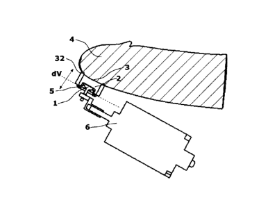
Fig. 4 shows an embodiment in which the applicator 11 is connected to the
pressure field
generation device 1 via a connector 8 in the form of a tube, so as to transmit
the alternating
pressure field generated by the pressure field generation device 1 to the
applicator 11, and
apply it to the penis through the opening 3. In particular, a first port 36 of
the connector 8 is
connected to a pneumatic outlet 35 of the pressure field generation device 1,
while a second
port 37 of the connector 8 is connected to the port 30 of the applicator 11.
This can be done,
for example, via plug connectors, as described in more detail below. The
connector 8 can be
configured in sections, or in a completely flexible manner.
The configuration of the stimulation device with a tube as a connector 8 can
serve for easy
use of the stimulation device, as the user only has to hold the applicator 11
in his hand. If
necessary, this can also be possible without a tube if the shape of the
stimulation device is
suitably configured, possibly with a short connecting piece (see, for example,
Fig. 17). If an
appropriate retaining device is provided at the same time, as described in
more detail below,
"hands-free" use can also be possible, in particular, since the pressure field
generation
device 1 can be placed, for example, next to, or on, the user.
A change in the cross-section of the pressure chamber 2, or of a pressure or
flow system,
which in addition to the pressure chamber 2 can also include the fluid channel
7, the
connector 8, and/or other cavities exposed to the alternating pressure field,
can affect the
flow velocity of the medium (in particular air), that is to say, a cross-
sectional constriction
means a flow acceleration and a cross-sectional expansion correspondingly
means a flow
deceleration.
16
CA 3069463 2020-01-23
. . , .
Since the pressure chamber 2 is placed on the penis in an almost sealed manner
and thus
an at least largely closed flow system is formed, there is virtually no
exchange of air with the
environment, which is why the removal of body fluid from the pressure field
generation device
is avoided, and the stimulation does not lead to the mucous membranes drying
out. The
temperature of the volume of air enclosed in the closed system quickly adjusts
to the body
temperature, by virtue of the relatively small volume. Furthermore, the
stimulation device can
be used without valves, which facilitates hygienic use.
Also with regard to hygienic use, a contact region defined by an accommodation
region 31, or
an accommodation chamber 34 of the applicator 11, is preferably open in the
region of the tip
of the glans 4. Thus, when using the stimulation device in accordance with the
invention, in
particular by virtue of the compact shape of the applicator 11, which is
preferably configured
to stimulate the frenulum 24, and thus has only to seal a small portion of the
penis from the
environment, the ejaculate can be discharged during orgasm. Cleaning is thus
simplified.
This provides a stimulation device that is improved in terms of hygiene, in
particular
compared to conventional closed stimulation devices.
As shown in Figures 5 and 6, the stimulation device has, in addition to the
pressure field
generation device 1, a control device 9, which can control a drive unit 6, and
in which the
modulation of the pressure field can be pre-stored. The control device 9 has
at least one
operating element 10, wherein the respective modulation of the pressure field
can be
changed by means of the operating element 10. In addition, the stimulation
device has a
housing (not shown), which can comprise the control device 9, the drive unit
6, the pressure
field generation device 1 and an internal battery 12, wherein the stimulation
device is
preferably designed as a portable hand-held device. The control unit 9 makes
it possible to
set a stimulation pattern from the stimulation patterns of the control unit 9
by means of an
operating element 10, wherein the drive unit 6 is controlled in accordance
with the set
stimulation pattern.
The drive unit 6, coupled to the flexible wall 5 of the pressure field
generation device 1, can,
for example, consist of a rotating electric motor 13 with a mechanical
transmission. The
mechanical transformation of the rotation of the electric motor 13 into a
translational
movement of the flexible wall 5 of the pressure field generation device 1 can
take place, for
example, by means of an eccentric 14, as shown schematically in Fig. 7.
Fig. 7 shows schematically the drive unit 6 in the form of a rotating electric
motor with
mechanical transformation and coupling to the flexible wall 5 of the pressure
field generation
17
CA 3069463 2020-01-23
. . .
device. By means of the control current supplied by the rotating electric
motor 13, for
example in the form of direct current, the rotational speed of the electric
motor 13 and thus
ultimately the frequency of the flexible wall 5 is varied and controlled. The
flexible wall 5 can
have a bead, which mechanically follows the strokes of the flexible wall 5, as
far as possible
without mechanical stress. The stroke of the flexible wall 5 is determined by
the defined
eccentric travel. The fixed piston stroke means a fixed reduction and increase
of the chamber
volume dV, and thus a corresponding fixed pressure increase or pressure
reduction, that is to
say, an approximately fixed amplitude of the alternating over- and under-
pressure.
Alternatively, the drive unit 6 coupled to the flexible wall 5 of the pressure
field generation
device 1 can consist of a linear electric motor 15, as shown in Figs. 8 and 9.
In the
electromagnetic transducer shown in Figs. 8 and 9, the flexible wall 5
connected to a carrier
16 is moved back and forth by at least one moving coil or plunger coil 17
attached to it, in
accordance with the coil supply, by means of the control current in the air
gap 18.
The flexible wall 5 of the pressure field generation device 1 is attached to a
carrier 16. The
flexible wall 5 can have a bead, which mechanically follows the strokes of the
flexible wall 5,
as far as possible without mechanical stresses. A moving coil 17 is wound
around the carrier
16, which coil is fed by the control current from a control unit during
operation. The moving
coil 17 consists of electrical conductors of a material that is as
electrically conductive as
possible (preferably copper), which conductors are insulated from each other
and from the
carrier 16 with an electrically insulating lacquer. The magnetic field is
generated by at least
one permanent magnet 19, preferably in ring form.
The magnetic flux, for example, is led by a rear pole plate 20 (preferably in
cylindrical form)
via the upper pole plate 21 (preferably in ring form) across the preferably
ring-form air gap to
the cylindrical pole core 22. The rear pole plate 20 and the upper pole plate
21 are made of
magnetically highly permeable material (preferably a soft magnetic material
alloy), as is the
pole core 22. Alternatively, a cylindrical permanent magnet can be used
instead of the pole
core 22, and accordingly a ring pole can be used instead of the permanent
magnet 19.
The carrier 16 with the moving coil 17 is structurally centred and guided in
the air gap 18 by
at least one mounting or suspension 23 (preferably made of plastic, textile
fabric, or paper) to
prevent wobbling movements of the moving coil 17. The mounting or suspension
23 is
attached to a frame.
18
CA 3069463 2020-01-23
. . = . , .
To move the flexible wall 5 the moving coil 17 is fed with an alternating
control current from a
control unit. The moving coil 17 is moved up or down by the Lorentz force,
depending on the
current direction, that is to say, the current polarity in the magnetic field
of the air gap 18. The
stroke of the deflection of the moving coil 17 is determined by the amplitude
of the control
current. The frequency of the alternating current corresponds to the frequency
of the moving
coil movement, and thus to the frequency of the piston or membrane movement.
The
frequency and the stroke of the moving coil 17, and thus the movement of the
flexible wall 5,
can thus be controlled independently of each other relatively easily by means
of the current
frequency and current amplitude. By virtue of the direct transmission, an
extended frequency
range is possible with this principle from below 1 Hz up to several hundred
Hz. A direct
current from a battery or accumulator is converted into an alternating current
signal.
Essential for the establishment of the desired alternating pressure field, in
particular with the
cited under- and over-pressures in the order of magnitude of pressure
differences of 20 mbar
to 800 mbar, is the sealing of the pressure chamber 2 from the environment, in
other words
the application of the contact region 31 with the sealing device 32 resting on
the penis, in
particular on the glans 4, and the formation of an at least largely closed
flow system. For this
purpose, the contact region 31 and in particular the sealing device 32 is
suitably configured
with regard to shape and material, as described below with the aid of
preferred embodiments.
Furthermore, a contact pressure sufficient for the build-up of the above-
mentioned under-
and over-pressures can be applied to the sealing device 32, as also described
below with the
aid of preferred embodiments. Needless to say, relevant characteristics, in
particular with
regard to the transmission of the alternating pressure field to the penis, are
common to all
embodiments and are not described with regard to each embodiment, simply to
avoid
repetition.
Fig. 10 shows an embodiment of an applicator 11, which, in addition to the
sealing device 32,
has anatomically shaped projections 33 in the contact region 31. Furthermore,
the contact
region 31 is configured so as to have a surface shape that supports the seal.
A sealing
device 32 is provided, which surrounds the opening 3 of the pressure chamber 2
of the
applicator 11. The sealing device 32 is designed as a rounded pliable bead
around the
opening 3, which can adapt to the shape of the penis when the applicator 11 is
applied to the
penis.
In addition, the projections 33 are provided, which essentially follow the
profile of the coronal
sulcus 25. This can support the sealing effect of the sealing device 32, such
that the
projections 33 can also be regarded as part of the sealing device 32. By
virtue of their
19
CA 3069463 2020-01-23
anatomical shape, the projections 33 can facilitate the correct positioning of
the applicator 11
on the penis, in particular in such a way that the frenulum 24 is at least
partially
accommodated in the pressure chamber 2. The material of the sealing device 32
is
preferably soft, for example a soft silicone or rubber. The projections 33 can
be made of the
same material or of a different material, for example one that is harder or
softer. The opening
3 of the pressure chamber 2 is designed in such a way that it can at least
partially
accommodate the frenulum 24, such that the alternating pressure field in the
pressure
chamber 2 can act directly on the frenulum 24.
In accordance with one embodiment, the contact pressure required for a seal
can be applied
by the user himself by means of hand pressure. Fig. 11 schematically shows
such an
applicator 11, applied to a penis, in which the pressure chamber 2 is sealed
against the glans
4 by the pressure applied by hand pressure. A retaining device or gripping
device in the form
of wing-like extensions 23 is formed, which the user can position in a largely
flexible manner
on the penis or the glans 4. In this manner, the sealing device is pressed
against the penis.
The opening 3 is designed to receive the frenulum 24 and parts, or all, of the
corona glandis
25. In this embodiment, the pressure chamber 2 expands towards the opening 3,
as can be
seen in the cross-sectional view in Fig. 11.
In accordance with another embodiment, as shown in Fig. 12, the necessary
contact
pressure can be achieved, for example, by an essentially ring-form retaining
device 26,
wherein the internal material stresses occurring during elastic deformation of
the ring 26 act
on the penis and on the sealing device. It is advantageous if the retaining
device 26 is open
in the region of the tip of the glans 4. However, a cap-like structure closed
at the tip is also
conceivable, which structure is elastically deformable like the ring-form
retaining device 26,
and thus holds the applicator 11 on the glans 4. In the embodiment shown in
Fig. 12, the
opening 3 of the pressure chamber 2 is sealed against the glans 4 after
extension and
placement of the ring-form retaining device 26, wherein the opening 3
accommodates the
frenulum 24 and parts, or all, of the corona glandis 25.
The ring-form and elastically deformable retaining device 26 shown in Fig. 12
can be
reinforced by a strap with a tightening mechanism 27, as shown in Fig. 13.
Here the sealing
is achieved by means of the internal stresses of the material when elastically
deformed and
additionally by a force applied against the glans 4 of the male member by
means of a strap.
Alternatively, in accordance with another embodiment, the necessary contact
pressure can
be applied solely by a strap- or band-form retaining device 26 with a fixing
or tightening
CA 3069463 2020-01-23
=
= = . =
mechanism 27, as shown in Fig. 14. The strap is particularly easy to fix, and
therefore
position, on the corona glandis 25. In addition, this retaining device 26 of
the applicator 11
can be adapted particularly easily to different diameters of the male member
in the region of
the glans 4.
In another variant of the applicator, as shown in Fig. 15, the retaining
device can be designed
separately from the applicator body 29. This means that, by selecting a
suitable retaining
device, the seal can be improved even with different member diameters, that is
to say, glans
diameters, and its use can be simplified with regard to the putting on and
taking off of the
stimulation device and its cleaning. This multi-piece design is shown in Fig.
15 using the
strap sealing system as an example. A retaining body 28 with a strap, separate
from the
applicator body 29, is arranged above the applicator body 29, such that the
necessary
contact pressure can be applied to the sealing device. The two parts can be of
the same
material, or of different materials.
The embodiments shown in Figs. 10 to 15 are, in particular, designed for
stationary or non-
moving use of the stimulation device or applicator 11. In other words, the
applicator 11 can,
in particular as regards its shape, the contact region 31 and the sealing
device 32, be
configured in such a way that it is placed on the penis and, if necessary,
secured by a
retaining device, but without being moved. Here, for stimulation, the
alternating pressure field
is applied via the opening 3, in particular onto the frenulum 24.
However, it may be desired that the applicator can be moved over the shaft of
the penis, the
corona! sulcus 25, the corona glandis and the glans 4. At the same time,
however, when
applying a contact pressure or a compressive force, a sealing connection
should be created
so as to achieve stimulation, as in the other embodiments, by applying the
alternating
pressure field via the opening 3. The applicator in accordance with the
embodiments of Figs.
16 to 21 is configured in such a way that it can be moved along the shaft of
the penis, in
particular by releasing, or at least relaxing, the contact pressure. However,
movement can
also be possible while maintaining the contact pressure.
For this purpose, the sealing device 32 is preferably configured in such a way
that, on the
one hand, it adapts itself to the surface of the coronal sulcus and other
regions on the penis,
by virtue of the applied contact pressure and bead-like lips around the
opening 3 of the
pressure chamber 2, and applies a seal, and, on the other hand, can be moved
when the
contact pressure is released or relaxed, or when a contact pressure is applied
or maintained.
Advantageously, the contact region 31 extends around the entire periphery of
the penis and
21
CA 3069463 2020-01-23
. .
. = . .
defines a peripherally closed accommodation chamber 34 (Figs. 16 to 20), but
can also be
open at the periphery (Fig. 21). The retaining devices described in what
follows are also
suitable for fixing the applicator to the penis, but can be relaxed or
released so as to allow the
applicator to be moved along the penis shaft. During a movement the
alternating pressure
field can still be generated or switched off. The sealing device can form a
sliding seal, such
that at least a partial sealing effect up to the same, or almost the same,
sealing effect as in
stationary operation can be achieved even when moving, and the alternating
pressure field
can be built up in the pressure chamber 2 and applied to the penis through the
opening 3.
In Fig. 16 an example of an applicator 111 is shown, which has a peripherally
(or
circumferentially) continuous contact region 31 and thus a peripherally closed
accommodation chamber 34, into which the penis can be introduced. In a similar
manner to
the embodiments described above, the applicator 111 has a port 30, via which
an alternating
pressure field generated by a pressure field generation device 1 can be
applied to a pressure
chamber 2 of the applicator 111 and finally, via the opening 3, to a portion
of the penis to be
stimulated, such as the frenulum. To seal the pressure chamber 2 from the
environment, a
sealing device 32 is formed around the opening 3 in the contact region 31.
The applicator 111 has a rigid shell, which comprises a first part 45 with the
port 30, and an
opposing second part 46. A soft insert 47, made, for example, of silicone, is
arranged in the
shell, which has the contact region 31, and rests against the penis during
use. The parts 45,
46 of the shell are spaced apart when the applicator 111 is in the unloaded
state, and can be
moved together by hand. This compresses the soft insert 47 such that the
contact pressure
of the sealing device 32 on the penis is increased. The compression of the
insert 47 can be
facilitated by providing one or a plurality of indentations 48. By the
application of sufficient
contact pressure, the pressure chamber 2 is sealed from the environment and an
alternating
pressure field can be applied to the penis.
The sealing device 32 is also designed in such a way, for example so as to be
soft and
rounded, that the applicator 111 can also be moved along the penis shaft. It
is possible that
sufficient contact pressure and thus sufficient sealing of the pressure
chamber 2 for the
application of an alternating pressure field can be achieved even during
movement. However,
if the contact pressure is too low, the establishment of the alternating
pressure field can be
impaired. In use, a combined stimulation can thus be achieved, wherein the
applicator 111,
for example, can be moved such that, in addition to the friction generated, it
rests on the
penis in a sealing position, at least in phases, such that in these positions
a pneumatic
stimulation is generated by means of the pressure field. The sealing position
can also be in
22
CA 3069463 2020-01-23
. . . . . .
motion, depending on the location of the penis. For example, a moving seal can
be easier in
the penile shaft region than in the glans region. However, a user may wish to
switch off the
pressure field generation device 1 and use the applicator for manual
stimulation only. If
necessary, structures such as nubs, ribs, and similar (not shown) can be
provided on the
surface of the insert 47, that is to say, in the contact region 31, so as to
increase the
stimulation by friction in this case.
Fig. 17 shows the applicator 111 connected with a pressure field generation
device 1. The
hand of a user is indicated, which holds the applicator 111 or presses it
together as required.
Here the pneumatic output port 35 of the pressure field generation device 1 is
directly
connected to the port 30 of the applicator 111. It is to be understood that a
connector 8, for
example a tube, can be placed between the pressure field generation device 1
and the
applicator 111 for connection, as described above.
Fig. 18 shows one part of an embodiment of an applicator 111, which is similar
to the one
shown in Fig. 16, here too an increase in contact pressure is achieved by
manually pressing
the two parts 45, 46 of the shell together. However, a fixing device is
provided which fixes the
shell in a desired position, and maintains the contact pressure even after the
applicator is
released. In particular, a latching mechanism 61 is provided, whereby the
clamping force
resulting from compression is maintained, even if no external force is applied
to the shell.
This is achieved by the interlocking of corresponding surface profiles, such
as teeth. A
mechanism 62 is provided, which releases the latching mechanism 61 by suitable
displacement of the surface profiles relative to one another.
In the embodiment of an applicator 111 shown in Fig. 19, which is otherwise
similar to that
shown in Fig. 16, an increase in the contact pressure is achieved by means of
a clamping
device. By actuating the clamping device, for example by means of a rotary
knob 60, pull
cords 63 are tensioned. The pull cords 63 can be located in a guide channel
(not shown) in
both parts 45 and 46 of the shell. A turning movement of the knob 60 tensions
the pull cords
63, moving the parts 45 and 46 towards one another and increasing the contact
pressure on
the penis. The clamping device preferably has a fixing device (not shown) with
a latching
function that prevents the applied clamping force from being released
unintentionally.
Advantageously a mechanism for releasing the latching function is provided.
In the embodiment of an applicator 111 shown in Fig. 20, which is otherwise
similar to the
one shown in Fig. 16, an increase in the contact pressure is achieved by means
of at least
one air cushion 64, which is arranged between the shell 49, which here is
designed in one
23
CA 3069463 2020-01-23
, . = = = .
piece, and the insert 47. By inflating the air cushion 64, in particular with
air, the diameter of
the cavity 34 of the applicator 111 can be reduced at least in some sections,
and the contact
pressure on the penis can be increased. A one-way valve (not shown) can be
provided so as
to release the air from the air cushion 64 and thus reduce the contact
pressure again.
In accordance with the embodiment shown in Fig. 21, the applicator 211 has a
wing-like shell
with a first part 245 and a second part 246, which are connected to each other
via a hinge
250 such that they can move, in particular can swivel together. The contact
region 31 does
not completely enclose the penis. A torsion spring (not shown) is preferably
provided, which
forces a movement of the parts 245 and 246 of the shell away from one another
into an open
position. A fixing device (not shown) with a latching function can be
provided, which fixes the
applicator 211 in a constricted position caused by a user by the application
of a force. A
mechanism for releasing the latched position can also be provided.
Fig. 22 shows a coupling device 40, which serves in particular as a backflow
valve. For
hygienic reasons, when using a connector 8 in the form of a tube, care must be
taken to
ensure that no secretions are sucked into the tube as a result of capillary
action, and are not
deposited in the latter. The coupling device 40 is placed between the tube 8
and the
applicator 11, or between two sections 38, 39 of the tube 8, wherein the
section 38 leads to
the pressure field generation device 1, while the section 39 leads to the
applicator 11. It is
advantageous to position the coupling device 40 close to the applicator 11
such that the
section 39 of the tube 8 to be cleaned, which points towards the applicator
11, is as short as
possible.
The coupling device 40 has a membrane 41, which divides a cavity of the
coupling device 40
into two chambers 42, 43, such that no fluid can pass from the chamber 43 into
the chamber
42, that is to say, in the direction from the applicator 11 to the pressure
field generation
device 1. A pressure change, in particular due to the alternating pressure
field generated by
the pressure field generation device 1, causes a deflection of the membrane
41, such that the
alternating pressure field is transmitted despite prevention of a fluid flow.
In particular for
cleaning, the coupling device 40 can be separated by releasing a fastening
mechanism 44,
and the section 39 of the tube 8 can be cleaned with the applicator 11. It is
not necessary to
clean the section 38 of the tube 8, as no fluid can enter the section 38 by
virtue of the fluid-
impermeable membrane 41.
Fig. 23 shows an example of the design of a connection mechanism in the form
of a fluid-
tight plug connector. By means of the connecting mechanism, any applicator 11,
for example
24
CA 3069463 2020-01-23
. -
. = = =
one of the applicators described above, can be connected directly to a
pressure field
generation device 1. Alternatively, the connection mechanism can be used to
connect a
connector 8, for example a tube, to an applicator 11, or a pressure field
generation device 1,
or both. A plug connector allows an easy assembly of a stimulation device. The
connector
shown in Fig. 23 has a first part 51 with a socket, into which an extension of
a second part 52
can be introduced. For sealing, an 0-ring can, for example, be provided in at
least one of the
connector parts, or in both.
It is to be understood that any aspects of the preferred embodiments described
above can be
combined in an appropriate manner. In particular, the preferred embodiments
are only
exemplary. For example, various aspects of the applicator, such as the sealing
device,
pressure chamber, opening, contact region, accommodation chamber, and
retaining device,
can be combined in any manner so as to create an applicator in accordance with
the
invention for applying an alternating pressure field to a region of a penis to
be stimulated, in
particular the glans, preferably the frenulum. Regardless of the specific
configuration of the
applicator, the applicator can also be directly connected, or can be
connected, to a pressure
field generation device, or a connector such as a tube can be provided for
this purpose.
Provision can also be made for one or a plurality of the applicators
described, or even a
plurality of applicators of the same type, to be provided in a set, together
with a pressure field
generation device and, if required, a suitable connector.
CA 3069463 2020-01-23