Note: Descriptions are shown in the official language in which they were submitted.
CA 03069464 2020-01-08
WO 2019/023544
PCT/US2018/044038
LOWER BACK AND POSTURE SUPPORT DEVICE
COPYRIGHT NOTICE
[0001] A portion of the disclosure of this patent document
contains material which is
subject to copyright or mask work protection. The copyright or mask work owner
has no
objection to the facsimile reproduction by anyone of the patent document or
the patent
disclosure, as it appears in the Patent and Trademark Office patent file or
records, but
otherwise reserves all copyright or mask work rights whatsoever.
CROSS REFERENCE TO RELATED APPLICATIONS
[0002] This application claims the benefit of U.S. Provisional Application
Serial Number
62/538,525 filed July 28, 2017, and U.S. Provisional Application Serial Number
62/580,180
filed November 1, 2017, the disclosure of each of which is hereby incorporated
herein by
reference in its entirety.
BACKGROUND
[0003] The present invention relates to a spine orienting and supporting
device for use with a
variety of types of seats, for example, automotive seats, heavy truck seats,
airline seats, mass
transit seats or office type seating, in order to properly position and
support the sacrum, which in
turn will properly position the spine of the individual using the seat. The
spine orienting and
supporting device, preferably made from thermoplastics, adjusts and/or
supports the sacrum
thereby orienting the pelvis to assist in maintaining the spine in neutral
equilibrium. In some
embodiments, the support is preferably separate from the seat and includes a
main body and a
support frame. In other embodiments, the support is preferably integrated into
the frame of the
existing seat of interest. The main body has a vented center relief area that
flexes to relieve
and/or redistribute localized pressure from the spine and to support the
user's sacrum. In other
embodiments, the center relief area of the main body is optionally vented. In
still other
embodiments, preferably in embodiments where the support is integrated into
the seat frame,
venting of the center relief area of the main body is typically not required
and generally can be
omitted, essentially providing an enlarged center relief portion absent any
venting over the space
1
CA 03069464 2020-01-08
WO 2019/023544
PCT/US2018/044038
occupied by both the center relief area and center relief portion. The
integrated main body and
support frame properly locate the device on the seat while providing
resistance or pressure relief
to different positions of the user's lower spine and pelvis, creating a spine
orientation that is
more conducive to user comfort, leading to reductions in work fatigue. The
device will also fill
an otherwise empty space between the bottom and rear seat sections, thereby
further improving
posture while seated.
[0004] Many types of spine supporting devices have been previously
suggested. Primarily
these have ranged from those that extend across the whole lumbar region to
others that extend
upwardly to fit against the upper back. Such devices have typically been in
the form of a pillow
or a shaped seat that will tend to fit the curvature of the lumbar region of a
person's spine when
seated in that seat.
[0005] Other types of spine supporting devices focus on the sacral
region of the spine.
Among these are US Patent 7,429,080 and US Patent 7,445,008. US Patent
7,429,080 is directed
to a sacral support assembly for use with a seat and is reported to provide
adjustable, stabilizing
support to a user's sacrum and sacral-pelvic anatomy to reduce fatigue,
increase comfort, stability
and posture for a user, and a system for adjusting and controlling the load
distribution from the
sacral anatomy to the anatomical structures adjacent to a user's sacrum, for
example, the pelvis
and lumbar regions. US Patent 7,445,008 discloses a cushion for use with a
variety of types of
seats that can adjust the sacrum to assist in maintaining the spine in
equilibrium. The central area
of the cushion has a plurality of inserts that individually have varying
compressibility. Through
the use of such inserts or devices, a user can select an insert most nearly
suited to the user and
the seat to provide a compression result providing sufficient pressure
concentrated on the sacrum
of the user to properly position the sacrum.
[0006] Common types of seating products do not meet user
expectations for lower back
comfort and support. Seating comfort is a key reason for users to purchase
these products or use
these products. In order to improve lower back comfort, manufacturers often
add additional
support in the lumbar region of the seat back via contouring of the cushion,
or by adding
adjustable lumbar support devices to the seat back, under the cushion and
upholstery. These
lumbar contour changes or lumbar support devices may provide users short term
comfort and
2
CA 03069464 2020-01-08
WO 2019/023544
PCT/US2018/044038
relief of lower back pain, but they generally do not provide long term comfort
and pain relief at
least in part due to their shape and location in relation to the users spine.
BRIEF SUMMARY
[0007] The present invention is directed, in part, to portable
sacral support devices
comprising a main body, wherein the main body comprises a vented center relief
portion
surrounded by and connected to a center support portion; relief arms disposed
laterally to the
center support portion; an upper support portion connected to the center
support portion and the
relief arms; and a support skirt connected to the center support portion and
to the relief arms; and
a support frame attached to the main body, the support frame comprising an
outer arch; an inner
arch medial to the outer arch; and a pedestal connected to the inner and outer
arches.
[0008] The present invention is also directed, in part, to
integrated sacral support devices
comprising a main body, wherein the main body comprises an optionally vented
center relief
portion surrounded by and connected to a center support portion; relief arms
disposed laterally to
the center support portion; an upper support portion connected to the center
support portion and
the relief arms; and a support skirt connected to the center support portion
and to the relief arms;
and a support frame attached to the main body, the support frame comprising an
outer arch; an
inner arch medial to the outer arch. In such embodiments where the support
device is integrated,
a pedestal is not typically required, but rather, the inner and outer arches
are conjoined at the
base portion of the support frame.
[0009] The present invention relates to spine-orienting devices for use
with a variety of types
of seats, for example, automotive seats, heavy truck seats, airline seats,
mass transit seats or
office type seating, in order to properly position and support the sacrum,
which in turn will
properly position and/or orient the spine of the individual using the seat.
The devices are
designed to be positioned in the gap or opening between the seat pan and the
seat back and
aligned to the centerline of the seat. The spine-orienting and/or supporting
devices, preferably
made from thermoplastics, adjusts and/or the sacrum thereby orienting the
pelvis to assist in
maintaining the spine in neutral equilibrium. In certain embodiments, the
support devices are
preferably separate from the seat and include a main body and a support frame,
while in others,
they are preferably directly attached and/or otherwise integrated into the
frame of the seat of
3
CA 03069464 2020-01-08
WO 2019/023544
PCT/US2018/044038
choice. In some embodiments, the main body has a slotted center relief area
that flexes to
provide resistance or pressure relief to different positions of the user's
lower spine, creating a
spine orientation that is more conducive to user comfort, leading to
reductions in work fatigue.
The device also fills an otherwise empty space between the bottom and rear
seat sections,
thereby further improving posture while seated. It was found that with many
types of seating, for
example, automotive seats, heavy truck seats, airline seats, mass transit
seats or office type
seating, there is usually a relatively large gap between certain portions of
the seat back and the
posterior of the seat user proximate to the user's sacral region. When the
sacral area of the seat
user's spine remains unsupported, the risk of fatigue, back pain and other
related problems
increases. The inventors have found that the prevalence of these conditions
that may otherwise
develop may be avoided through use of portable, or alternatively through
integrated devices that
work with a variety of seat types. Because individuals vary widely in terms of
their total body
weight, their frame size, and the amount of support necessary to achieve some
measure of relief,
the support devices would also need to be adjustable to each individual and to
each seating
environment.
[0010] This invention is directed to these and other important
ends, and further achieves
those requirements. The invention is a molded thermoplastic spinal support
device that is easy to
use, provides the ability to produce the desired isolated forces and relief on
targeted sacral sub-
regions of the user's anatomy, yet permits easy adjustment and fit to an
individual user's back
support requirements. Additionally, the present invention also achieves its
effectiveness in being
able to correctly position a user's sacrum in a variety of types of seats.
[0011] The molded device includes a main body, having an
optionally vented center relief
portion surrounded by and connected to a center support portion, relief arms
disposed laterally to
the center support portion, an upper support portion connected to the center
support portion and
the relief arms, and a support skirt connected to the center support portion
and to the relief arms.
In addition to the main body, the device also includes a support frame
attached to the main body.
The support frame comprises an outer arch; an inner arch medial to the outer
arch, and a pedestal
connected to the inner and outer arches.
4
CA 03069464 2020-01-08
WO 2019/023544
PCT/US2018/044038
[0012] The desired level for such an applied, and isolated,
readjusting force should be
enough to properly reposition the sacrum, yet not so much as might result in
pain or discomfort
to the user. The proper level of support, relief and/or pressure
redistribution will be that which
will make the support device virtually disappear as an additional seat
component. Additionally,
the main body is designed to permit those portions of the body adjacent the
sacrum to be
relatively less supported. While the sacrum itself needs to be supported, the
adjacent body
structure will desirably be able to move rearwardly, or fall back, by an
amount needed to achieve
the desired level of pelvic pivot to properly orient the spine.
[0013] Other objects, features, and characteristics of the present
invention will become
apparent upon consideration of the following description in the appended
claims with reference
to the accompanying drawings, all of which form a part of the specification,
and wherein like
reference numerals designate corresponding parts in the various figures.
BRIEF DESCRIPTION OF THE DRAWINGS
[0014] The invention is better understood by reading the following
detailed description with
reference to the accompanying drawings in which:
[0015] FIG. 1 is a front elevational view of an embodiment of the
present invention;
[0016] FIG. 2 is a rear elevational view of a main body of an
embodiment of the present
invention;
[0017] FIG. 3 is a front elevational view of a support frame of an
embodiment of the present
invention;
[0018] FIG. 4 is a rear elevational view of an embodiment of the
present invention;
[0019] FIG. 5A is a rear perspective view of an embodiment of the
present invention
showing an optional seat clip in a stowed position;
[0020] FIG. 5B is a rear perspective view of an embodiment of the
present invention
showing an optional seat clip in a seat-installed position;
[0021] FIG. 5C includes perspective and side views of an optional
clip for an embodiment
of the present invention;
5
CA 03069464 2020-01-08
WO 2019/023544
PCT/US2018/044038
[0022] FIG. 6 is a view of orientation and direction definitions
for embodiments of the
present invention;
[0023] FIG. 7 depicts an outline overlay of an embodiment of the
present invention onto the
pelvis and spine of a seated occupant;
[0024] FIG. 8 is a view of an optional cover for covering the forward face
of an embodiment
of a device of the present invention;
[0025] FIG. 9 is a rear perspective view of an embodiment of a
device of the present
invention having an optional cover and seat clip;
[0026] FIG. 10 is a front perspective view of an embodiment of a
device of the present
invention having an optional cover and optional seat clip;
[0027] FIG. 11 is a front perspective view of an embodiment of a
device of the present
invention having an optional seat clip;
[0028] FIG. 12 is a rear perspective view of an embodiment of a
device of the present
invention having an optional seat clip;
[0029] FIGS. 13A and 13B represent illustrations of an embodiment of an
integrated
lower back and posture support device of the present invention and its
attachment to either a
seat frame or back frame assembly springs or suspension;
[0030] FIG. 14 illustrates an exemplary embodiment of the
integrated device in a typical bus
or train seat type;
[0031] FIG. 15 illustrates a support frame exemplary embodiment for an
integrated support
device of the present invention;
[0032] FIG. 16A and 16B illustrate frontal and rear plan views of
a main body portion of an
integrated support device exemplary embodiment of the present invention;
[0033] FIG. 17 is a front elevational view of a main body element
of an embodiment of the
present invention;
[0034] FIG. 18 is a rear elevational view of a main body of an
embodiment of the present
invention;
[0035] FIG. 19 is a front elevational view of a support frame of
an embodiment of the
present invention;
6
CA 03069464 2020-01-08
WO 2019/023544
PCT/US2018/044038
[0036] FIG. 20 is a rear elevational view of an embodiment of the
present invention;
[0037] FIG. 21 includes rear perspective and side views of an
embodiment of a seat clip of
the present invention;
[0038] FIGS. 22A and 22B are rear perspective views of an
embodiment showing an
optional seat clip of the present invention in stowed and installed positions,
respectively;
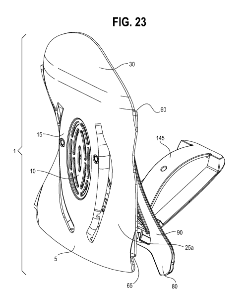
[0039] FIG. 23 is a front perspective view of an embodiment of the
present invention
showing an option seat clip;
[0040] FIG. 24 is a view of orientation and direction definitions
for embodiments of the
present invention; and
[0041] FIG. 25 illustrates a support frame exemplary embodiment for an
integrated support
device of the present invention.
DETAILED DESCRIPTION OF THE DRAWINGS AND THE PRESENTLY
PREFERRED EMBODIMENTS
[0042] As used herein, the modifier "rearward or "rearwardly"
refers to movement toward a
seat back when the device is placed in use. For example, the rearward face of
the main body is
that face more proximate to the seat back. The term "rearward curving denotes
that the arch is
curving in the direction of the seat back. Conversely, an element curving
"forward" denotes the
element curving away from (in a direction forward of and distil to) the seat
back in use.
[0043] As used herein, the term "thermoplastic" refers to a
plastic material, or
thermosoftening plastic, typically a polymer, that becomes pliable or moldable
above a specific
temperature and solidifies upon cooling. The intermolecular forces of the
thermoplastic material
weaken rapidly with increased temperature, allowing them to be reshaped by
heating and are
typically used to produce parts by various polymer processing techniques such
as injection
molding, compression molding, calendaring, and extrusion.
[0044] As used herein, the term "viscoelastic" refers to a material that
exhibits both viscous
and elastic properties when undergoing deformation, and, as such, exhibit time-
dependent strain.
Viscous materials, like honey, resist shear flow and strain linearly with time
when a stress is
applied. A viscoelastic substance changes shape when a stress is put on it and
goes back to its
original state when the stress is removed after a period of time.
7
CA 03069464 2020-01-08
WO 2019/023544
PCT/US2018/044038
[0045] As used herein, the term "flex modulus" refers to an
intensive property that is
computed as the ratio of stress to strain in flexural deformation, or the
tendency for a material to
bend. It is determined from the slope of a stress-strain curve produced by a
flexural test (such as
the ASTM D790 or ISO 178), and uses units of force per area.
[0046] As used herein, the term "elastomer", or "thermoplastic elastomer",
or alternately
"thermoplastic rubber" belong to a class of copolymers or a physical mix of
polymers (usually a
plastic and a rubber) which consist of materials with both thermoplastic and
elastomeric
properties. While most elastomers are thermosets, thermoplastics are in
contrast relatively easy
to use in manufacturing, for example, by injection molding. Thermoplastic
elastomers show
advantages typical of both rubbery materials and plastic materials. One
benefit of using
thermoplastic elastomers is the ability to stretch to moderate elongations and
return to its near
original shape creating a longer life and better physical range than other
materials.
[0047] LIST OF ELEMENTS
[0048] 1 lower back and posture support device
[0049] 2 main body
[0050] 5 support skirt
[0051] 10 center relief portion
[0052] 15 center support portion
[0053] 20 and 20a curved slots
[0054] 25 and 25a left and right relief arms
[0055] 30 upper support portion
[0056] 35 support skirt ribbing
[0057] 40 rear face of support skirt
[0058] 45 slots of center relief portion
[0059] 50 ribbing of center relief portion
[0060] 55 notching in support skirt ribbing
[0061] 60 upper notch for cushion
[0062] 65 lower notch for cushion
8
CA 03069464 2020-01-08
WO 2019/023544
PCT/US2018/044038
[0063] 70 Ribbing for center support portion
[0064] 75 notching in lateral ribs of upper support portion
[0065] 75a lateral ribs of upper support portion
[0066] 80 pedestal
[0067] 85 protrusion
[0068] 90 outer arch
[0069] 95 orifices in inner arch for attaching support frame to
main body
[0070] 100 portal
[0071] 105 horseshoe-shaped slot
[0072] 110 inner arch
[0073] 115 slot
[0074] 120 rivet
[0075] 125 and 125a outer edges of relief arms
[0076] 130 support frame
[0077] 140 notching in center support portion ribbing
[0078] 145 seat clip
[0079] 150 hook
[0080] 155 cover
[0081] 160 cover upper pocket
[0082] 165 cover lower pocket
[0083] 170 cover tab
[0084] 175 support frame for integrated device
[0085] 180 seat support frame
[0086] 185 seat cushioning and/or fabric seat covering
[0087] 190 springs or suspension in the back frame assembly
[0088] 195 integrated device main body center support portion
[0089] 200 base portion of integrated device support frame where
inner and outer arch are
conjoined
9
CA 03069464 2020-01-08
WO 2019/023544
PCT/US2018/044038
[0090] 205 orifice(s) in main body for attaching main body of an
integrated device
embodiment to its support frame
[0091] 210 exemplary options for attachment features and locations
of the integrated device
support frame to the seat back support frame, springs, and/or suspension
[0092] 220 L4, L5 vertabrae
[0093] 230 pelvis
[0094] 240 PSIS prominence
[0095] 250 sacrum
[0096] 260 outline of a main body of a back support device
oriented over the pelvis and
spine of a seated occupant
[0097] 270 + Y axis bend/flex
[0098] 280 + X axis bend/flex
[0099] Embodiments of the portable sacral support device of the
present invention include a
main body 2 and a support frame 130 attached to the main body 2. The main
bodies in these
embodiments have a center support portion, an upper support portion connected
to the center
support portion, and a support skirt connected to the center support portion.
The main bodies
may also include at least one of, and preferably each of the following: (1) a
vented center relief
portion surrounded by and connected to the center support portion; and (2)
relief arms disposed
laterally to the center support portion and/or connected to the support skirt
portion. The support
frames attached to the main bodies in these embodiments includes an inner arch
and a pedestal
connected to the inner arch. The support frames may further include an outer
arch. In certain
embodiments, the support frame comprises an outer arch; an inner arch medial
to the outer arch,
wherein the outer arch and the inner arch are connected to the pedestal.
Turning to the drawings,
principally FIGS. 1-4, 11 and 12, the main body 2 of the exemplary portable
support device 1,
generally shown in FIG. 1, includes a slotted (or vented) center relief
portion 10 (slots 45)
connected to a center support portion 15, left and right relief arms 25 and
25a, respectively,
disposed laterally to the center support portion 15, an upper support portion
30 connected to the
center support portion 15 and to the relief arms 25 and 25a, and a support
skirt 5 connected to the
CA 03069464 2020-01-08
WO 2019/023544
PCT/US2018/044038
center support portion 15 and to the relief arms 25 and 25a. It is preferred
that the support device
1 be a molded product that is formed through one of a number of conventional
molding
techniques. The outer edge (125, 125a) of each relief arm (25, 25a) is
laterally curved toward the
midpoint of the center relief portion 10 such that the width of the main body
2 as defined by each
relief arm outer edge's inner most point (the waist) is more narrow than the
width of the main
body's upper support portion 30 and/or its skirt 5. Each relief arm (25, 25a)
forms an arc
rearwardly curving between its connections to the main body's upper support
portion 30 and
skirt 5. The center support portion 15, upper support portion 30, skirt 5 and
left relief arm 25
together define a curved slot 20 in the main body. Similarly, the center
support portion 15, upper
support portion 30, skirt 5 and right relief arm 25a together define a curved
slot 20a in the main
body 2 that minors slot 20 about the main body's y-axis. The center support
portion 15 is
substantially flat and acts to support the user's sacrum as well as provide
the means for
connecting the main body 2 with the support frame. The center support portion
deflects rearward
against the inner arch when pressure is applied from the user. The center
support portion when
viewed in conjunction with its rearward surface's ribs, is thicker so that the
center support
portion resists bending and remains flat. The laterally disposed relief arms
deflect forward
against the outer arch when pressure is applied to the center support portion
from the user. The
shape of the laterally disposed relief arms work to provide relief around the
user's posterior-
superior-iliac-spine (PSIS) prominence, at least in part by the narrow waist
of the main body
and/or the rearwardly curved arc. The upper support portion surface reacts and
flexes against the
user's lower lumbar vertebrae, conforming to the user's back regions at,
proximate and/or
adjacent to the lumbar vertebrae, generally L4 and/or L5, to relieve and or
redistribute pressure,
while the support skirt reacts and flexes against the user's buttocks,
conforming to the user's
buttocks shape. The one or more slots 45 in the center relief portion 10 allow
it a further degree
of flex rearwardly in addition to any flex inherent in the material used to
mold the main body.
This additional flex assists the device in relieving or redistributing
localized pressure exerted by
the sacral portion of the spine or belt loops and belts on the user's trousers
when the device is in
contact with the user's back. The main body 2 also includes means, preferably
rivets 120 for
attaching the main body 2 to the support frame 130. The means for attaching
the main body 2 to
11
CA 03069464 2020-01-08
WO 2019/023544
PCT/US2018/044038
the support frame 130 is not critical so long as it is strong enough to
maintain the attachment and
does not otherwise interfere with the function of the device or its comfort to
the user. Exemplary
means include rivets, which may be made of metal, preferably steel, and may be
constructed of
carbon steel or the like for ease of manufacturing and/or the minimization of
overall
manufacturing costs. Exemplary connecting orifices are shown in FIGS. 1 and
17a thorough
which attaching means are employed to attach the main body to exemplary
corresponding
orifices 95 in the seat support frame.
[00100] The rearward surface (shown in FIG.2) of the main body 2 comprises a
series of ribs.
Certain of the ribs 50 are associated with the vented (or slotted) center
relief portion, and some of
the ribs 70 are associated with the center support portion. Other ribs 35 and
75a, respectively,
are associated with the support skirt 5 or with the upper support portion 30.
In an alternate
embodiment, the rearward surface (shown in FIG.18) of the main body 2
comprises a series of
ribs, wherein certain of the ribs 50 are associated with the vented (or
slotted) center relief
portion, and some of the ribs 70 are associated with the center support
portion. Other ribs 35 are
associated with the support skirt 5. In either embodiment, the ribs, at least
in part as a function of
their size and/or quantity, independently provide structure, rigidity and/or
stiffness to the molded
material in the various portions of the main body.
[00101] In certain embodiments, at least some of the ribs are notched to
provide a further
degree of flexibility to portions of the main body to locally assist bending
or otherwise
conforming better to the individual lower back shape of the user, vertically
or laterally, while
maintaining overall structure, rigidity and/or strength to the molded material
in the various
portions of the main body. For example, notches 75 in the lateral ribs
associated with the upper
support portion, act as a flexing point to improve a degree of flexibility in
the lateral relief
portions (FIG. 2). Notches 55 allow the support skirt to flex rearward to
relieve pressure exerted
by user contact and to improve conformation with the shape of the user's
buttocks. Notches 140
allow rearward flex in the upper support portion to relieve pressure to the
lumbar area of the
spine and to improve conformation with the shape of the user's lumbar spine.
Contouring in the
lumbar area is primarily the result of bending of the upper support portion 30
about the notches
140. An alternate embodiment (See FIG. 18) includes a notch 55 extending
across central
12
CA 03069464 2020-01-08
WO 2019/023544
PCT/US2018/044038
support portion 15 and center relief portion 10 that allows the support skirt
to flex rearward to
relieve pressure exerted by user contact and to improve conformation with the
shape of the user's
buttocks. In this embodiment, notches 75 and/or 140 may be eliminated.
[00102] The main body 2 also optionally includes a pair of notched shoulders
60 and a pair of
notched shoulders 65. The positioning of the two pairs of notched shoulders
create an upper and
lower portion of the main body 2 that is slightly more narrow than the
shoulders' widest points.
An optional hourglass shaped cover 155, preferably padded or cushioned, having
a lower pocket
160 and/or upper pocket 165 suitable for receiving a portion of the support
skirt 5 and/or a
portion of the upper support portion 30 may be fitted over the forward face of
the device.
Preferably, the lower and/or upper portion of the main body 2 that are each
slightly more narrow
than the skirt's or shoulders' widest points may be received into the lower
and/or upper pocket of
the cover, respectively, as described immediately hereinabove. The cover
overlays at least a
portion of at least one of the slotted center relief portion, center support
portion, upper support
portion and support skirt, preferably at least a portion of each of the
slotted (or vented) center
relief portion, center support portion, upper support portion and support
skirt. If desired, the
cover cushion may be held in place by adding elongated connectable tabs 170,
preferably
VelcroTM tabs, to each of the lower and upper pockets. See FIGS. 8, 9 and 10.
[00103] The main body may be prepared by an injection molded process employing
a
thermoplastic in the mold. The thermoplastic should have viscoelastic
behavior. The type of
thermoplastic is not critical so long as the thermoplastic has viscoelastic
behavior. Exemplary
plastics include nylon, polypropylene, acrylonitrile butadiene-styrene (ABS)
and the like. The
flex modulus as determined by the ASTM D790 or ISO 178 method is typically in
the range of
from about 1000 to about 3000, preferably from about 1200 to about 2500, and
more preferably
from about 1400 to about 2000, and all combinations and subcombinations of
ranges thereof
Thermoplastic elastomers, such as polyester elastomers, are preferred
materials for preparation
of the main body.
[00104]
The support frame 130 is attached to the rearward side of the main body
2. The
support frame 130 includes an inner arch 110, an outer arch 90, and a pedestal
80 connected to
both the inner and outer arches. The angle of connection of the pedestal 80
with the inner and
13
CA 03069464 2020-01-08
WO 2019/023544
PCT/US2018/044038
outer arches is approximately 90 degrees. When the device is placed in
position on a seat of
interest to the user, the pedestal is designed to rest on the seat pan,
preferably seat pan cushion,
and assist in positioning and stabilizing the device against the seat surface.
The outer arch 90,
while curving forward, tilts inward (i.e., the upper portion of the outer arch
is relatively closer in
proximity to the seat back than the lower portion (portion in proximity to the
pedestal) against
the seat back and acts like a spring reacting against the relief arms 25. The
outer arch 90, which
curves forward from the pedestal 80 toward the relief arms, is designed when
in use so that at
least an upper portion of the outer arch rests against the seat back,
preferably seat back cushion,
and interacts with various support elements found therein. For example,
interactions may occur
between the seat back (or its cushion materials ), its inner springs and seat
back surface when the
device is in use. The forward curvature creates resistance to the lateral
relief arms of the main
body, and further provides a sliding surface on which the relief arms may rock
and/or flex
laterally as the main body 2 adjusts to contact by the user's back. The inner
arch 110, curves
initially forward from the pedestal 80 to provide a flexible fulcrum from
which the attached main
body 2 may cantilever or rock. The inner arch provides for resistance against
the center support
portion of the main body, as well the connection between the main body 2 and
the support frame.
Its contact with the center relief portion permits a surface for bending and
rolling contact with
the inner arch when pressure is applied to the center support portion,
directing the main body 2
rearward and upward. The bending of the inner arch causes a natural upward
lift of the center
support portion, helping to support the pelvis. The inner arch has means for
attaching to the
main body, such as orifices 95 through which typical fastening means can be
utilized to attach
the frame support to the main body. The inner arch 110 also defines a portal
100 that corresponds
to the vented center relief portion 10, to create additional space for the
slotted relief portion to
flex rearward of the device and toward or onto the seat back. The outer arch
90, inner arch 110
and pedestal together define a generally horseshoe-shaped slot 105, which
permits the inner and
outer arches to independently flex to respond to and to the main body and
resist deflections at the
points in contact with the main body. In certain embodiments, the frame
support also includes a
retaining bracket (or seat clip)145, which is hingeably attached to the frame
support. The
retaining bracket 145 is designed to insert between the seat back, preferably
seat back cushion,
14
CA 03069464 2020-01-08
WO 2019/023544
PCT/US2018/044038
and the seat pan, preferably seat pan cushion, to assist in stabilizing the
device in use (FIGS. 5A,
5B, and 5C). Its hingeable design permits the retaining bracket to swing
upward and to be
stowed in the recess defined by the rearward face of the inner arch when the
device is not in use.
In some embodiments, the retaining bracket is attached through slot 115 and
mated with
protrusion (or pivot) 85 in the inner arch employing hingeable means such as a
hook 150 and
pivot 85 mechanism. This mechanism also permits the removal of the optional
retaining bracket
when it is not needed to stabilize the device in use. In alternate embodiments
(See FIGS. 22A,
22B), the retaining bracket is mated with protrusion (or pivot) 85 in the
inner arch employing
hingeable means such as a hook 150 and pivot 85 mechanism, which permits the
removal of the
optional retaining bracket when it is not needed to stabilize the device in
use.
[00105] The support frame 130 may be prepared by an injection molded process
employing a
thermoplastic in the mold. The thermoplastic should have viscoelastic
behavior. The type of
thermoplastic is not critical so long as the thermoplastic has viscoelastic
behavior. Exemplary
plastics include nylon, polypropylene, acrylonitrile butadiene-styrene (ABS)
and the like. The
flex modulus as determined by the ASTM D790 or ISO 178 method is typically in
the range of
from about 1000 to about 3000, preferably from about 1200 to about 2500, and
more preferably
from about 1400 to about 2000, and all combinations and subcombinations of
ranges thereof
Elastomers, such as polyester elastomers, are preferred materials for
preparation of the support
frame.
[00106] Embodiments of the device are designed to provide both X axis and/or Y
axis bend or
flex independently through the interaction of the main body 2 with the support
frame 130 and
contact in use with the seat back and seat pan (FIG. 6). One of the features
of the device's
structural properties in the Z direction is the providing of support for the
spine. As described
herein, the rearward surface of the main body 2 includes a series of ribs that
are independently
sized to support the spine and/or provide degrees of structural rigidity as
required in use.
[00107] When correctly positioned on the seat, the surface portions of the
main body 2 orient
and conform themselves with regard to the sacrum, pelvis and spine of the
seated occupant as
shown in FIG. 7. For example, the upper support portion of the main body 2
generally associates
with the L4 and L5 lumbar vertebrae 220, the center relief portion and center
support portion
CA 03069464 2020-01-08
WO 2019/023544
PCT/US2018/044038
associate with the sacral region 250, the relief arms curve rearwardly to
relieve pressure
associated from contact with the posterior superior iliac spine (PSIS)
prominence 240 and/or
assist in centering the right and left portions of the pelvis 230 with the
device.
[00108] In use, the device provides a system of spring forces and flexible
surfaces working in
parallel or series to support and flex the main body 2 surfaces when pressure
is applied by the
user. For example, when a user's spine comes into contact with the device,
user pressure against
the main body 2 of the device 1 is offset by opposite forces arising from the
inner arch 110, as it
curves initially forward from the pedestal 80 to provide a flexible fulcrum
from which the
attached main body 2 may cantilever or rock. In doing so, the inner arch also
provides resistance
against the center support portion of the main body. This resistance and
rigidity of the center
support portion is sufficient to support the sacrum, but not so much as to
pressure the nerves in
the pelvic region. The inner arch's contact with the center relief portion
permits a surface for
rolling contact with the inner arch, when pressure is applied to the center
support portion,
directing the main body 2 inward and upward. In addition, the relief the outer
arch 90, which
curves rearward from the pedestal 80, is designed when in use so that at least
an upper portion of
the outer arch rests against the seat back and interacts with various support
elements found
therein. The curvature of the outer arch creates resistance to any flex of the
relief arms in the Z
direction as well as further providing a sliding surface on which the relief
arms may rock about
an axis parallel to the device's X-axis as the main body adjusts to contact by
the user's back. As
would be understood by the skilled artisan, the seat back support cushions
and/or springs
independently assist the support frame 130 in providing structured resistance
to the device.
[00109] An alternate embodiment of the portable sacral support device of the
present
invention is generally shown in FIGS. 17-23. This embodiment contains many of
the same
elements disclosed hereinabove for portable sacral support devices (See also
principally FIGS. 1-
4, 11, and 12). In the alternate embodiment shown in FIG. 18, the rearward
surface of the main
body 2 comprises a series of ribs generally represented by a substantially
oval latticework of
intersecting ribs. The latticework spans the rearward surface of the main body
from about curved
slot 20 to about curved slot 20a, and its upper edge extends upward to a point
located
horizontally between the two upper notches for cushion 60. The latticework of
ribbing extends
16
CA 03069464 2020-01-08
WO 2019/023544
PCT/US2018/044038
downward to about a point between the lower ends of the two curved slots 20
and 20a. Certain of
the ribs 50 are associated with the vented (or slotted) center relief portion,
and some of the ribs
70 are associated with the center support portion. Other ribs 35 are
associated with the support
skirt 5. In this arrangement of rib latticework, ribs 75a (see FIG. 2) may be
eliminated, which
also allows removal of notches 75 and 140 from the latticework. The alternate
embodiment
replaces notches 55 (see FIG. 2) on the rearward side of main body 2 with a
horizontal notch 55
(FIG. 18) spanning the center relief portion 10 and the center support portion
15 from slot 20 to
curved slot 20a. The portal 100 of support frame 130 is extended downward to
protrusion 85
such that slot 115 (see FIG. 3) may be eliminated in the alternative
embodiment (FIG. 19).
[00110] Other embodiments of lower back and posture supporting devices of the
present
invention are capable of being integrated into common seating products.
Accordingly, the
present invention includes support devices capable of attachment and/or
integration into a wide
range of seating products, as well as the seats having the lower back and
posture supporting
devices integrated into the seat frames.
[00111] The lower back and posture support devices of the present invention
can be modified,
enabling it to be attached/integrated into these common types of seats. Given
the advantages
described herein regarding the superior comfort and support provided by the
portable devices of
the present invention, it appeared advantageous to further modify the devices
allowing them to
integrate into existing types of seating products to improve lower back
comfort and relieve lower
back pain.
[00112] Any type of seating product may be considered for integration with the
devices of the
present invention. Examples of such seats include but are not limited to
automotive and/or light
truck seating, heavy truck seating, bus and/or train seating, residential
recliner seating, office
seating, and airline cabin seating, and the like. Generally speaking,
integrating the present
inventive device into common seats should be feasible on any seating product
that is typically
constructed from an inner frame support structure and covered by cushion
materials such as
polyurethane foam and fabric.
[00113] A typical construction for common seating products includes a back
support frame
assembly surrounded by cushion materials and fabric. The back support frame is
typically a
17
CA 03069464 2020-01-08
WO 2019/023544
PCT/US2018/044038
weldment of steel or other common metal, or a wood frame. An array of metal
wire or elastic
springs often attaches to the support frame and supports the cushion material,
or in other cases,
the frame supports the cushion material directly.
[00114] The devices capable of integration into common seating types include a
main body
and support frame as disclosed herein. Means for attaching the support frame
of the device to
the wire springs or suspension in the back frame assembly integrate the
devices into the seat.
This means can include includes features allowing attachment to the wire
springs or suspension
in the back frame assembly. The support frames can be manufactured from any
materials that
provide the functionality as described herein and further enable attachment to
the desired seat
frames.
[00115] Embodiments of the integrated sacral support device of the present
invention include
a main body 2 and a support frame 130 attached to the main body 2. The main
bodies in these
embodiments have a center support portion 195, an upper support portion 30
connected to the
center support portion 195, and a support skirt 5 connected to the center
support portion. The
main bodies may also include at least one of: (1) a vented center relief
portion surrounded by
and connected to the center support portion; and (2) relief arms disposed
laterally to the center
support portion and/or connected to the support skirt portion, preferably
relief arms. The support
frames attached to the main bodies in these embodiments comprise an outer arch
and an inner
arch medial to the outer arch. In such embodiments where the support device is
integrated, a
pedestal is not typically required, but rather, the inner and outer arches are
conjoined at the base
portion 200 of the support frame. Turning to the drawings, principally FIGS. 1-
4, 11, 12, 13A,
13B, 14, 15, 16A, 16B, and 25, the main body 2 of the exemplary integrated
support device 1,
generally shown in FIGS. 13, 16A and 16B, includes a center support portion
195, left and right
relief arms 25 and 25a, respectively, disposed laterally to the center support
portion 195, an
upper support portion 30 connected to the center support portion 195 and to
the relief arms 25
and 25a, and a support skirt 5 connected to the center support portion 195 and
to the relief arms
25 and 25a. It is preferred that the support device 1 be a molded product that
is formed through
one of a number of conventional molding techniques. The outer edge (125, 125a)
of each relief
arm (25, 25a) is laterally curved toward the midpoint of the center relief
portion 10 such that the
18
CA 03069464 2020-01-08
WO 2019/023544
PCT/US2018/044038
width of the main body 2 as defined by each relief arm outer edge's inner most
point (the waist)
is more narrow than the width of the main body's upper support portion 30
and/or its skirt 5.
Each relief arm (25, 25a) forms an arc rearwardly curving between its
connections to the main
body's upper support portion 30 and skirt 5. The center support portion 195,
upper support
portion 30, skirt 5 and left relief arm 25 together define a curved slot 20 in
the main body.
Similarly, the center support portion 195, upper support portion 30, skirt 5
and right relief arm
25a together define a curved slot 20a in the main body 2 that mirrors slot 20
about the main
body's y-axis. The center support portion 195 is substantially flat and acts
to support the user's
sacrum as well as provide the means for connecting the main body 2 with the
support frame.
The center support portion deflects rearward against the inner arch when
pressure is applied from
the user. The center support portion when viewed in conjunction with its
rearward surface's ribs,
is thicker so that the center support portion resists bending and remains
flat. The laterally
disposed relief arms deflect forward against the outer arch when pressure is
applied to the center
support portion from the user. The shape of the laterally disposed relief arms
work to provide
relief around the user's posterior-superior-iliac-spine (PSIS) prominence, at
least in part by the
narrow waist of the main body and/or the rearwardly curved arc. The upper
support portion
surface reacts and flexes against the user's lower lumbar vertebrae,
conforming to the user's
back regions at, proximate and/or adjacent to the lumbar vertebrae, generally
L4 and/or L5, to
relieve and or redistribute pressure, while the support skirt reacts and
flexes against the user's
buttocks, conforming to the user's buttocks shape. The main body 2 also
includes means,
preferably rivets 120 for attaching the main body 2 to the support frame 130.
The means for
attaching the main body 2 to the support frame 130 is not critical so long as
it is strong enough to
maintain the attachment and does not otherwise interfere with the function of
the device or its
comfort to the user. Exemplary means include rivets, which may be made of
metal, preferably
steel, and may be constructed of carbon steel or the like for ease of
manufacturing and/or the
minimization of overall manufacturing costs. Exemplary connecting orifices are
shown in FIGS.
1 and 16A thorough which attaching means are employed to attach the main body
to exemplary
corresponding orifices 95 in the seat support frame.
19
CA 03069464 2020-01-08
WO 2019/023544
PCT/US2018/044038
[00116] The rearward surface (shown in FIG.2) of the main body 2 comprises a
series of ribs.
Certain of the ribs 50 and/or 70 are associated with the center support
portion. In the integrated
device, the center support portion encompasses the space occupied by both the
vented center
relief portion and center support portion shown for any one of the exemplary
portable devices
illustrated in other figures herein. Other ribs 35 and 75a, respectively, are
associated with the
support skirt 5 or with the upper support portion 30. In an alternate
embodiment, the rearward
surface (shown in FIG. 18) of the main body 2 comprises a series of ribs,
wherein certain of the
ribs 50 are associated with the vented (or slotted) center relief portion, and
some of the ribs 70
are associated with the center support portion. Other ribs 35 are associated
with the support skirt
5. In either embodiment, the ribs, at least in part at least in part as a
function of their size and/or
quantity, independently provide structure, rigidity and/or stiffness to the
molded material in the
various portions of the main body.
[00117] In certain embodiments, at least some of the ribs are notched to
provide a further
degree of flexibility to portions of the main body to locally assist bending
or otherwise
conforming better to the individual lower back shape of the user, vertically
or laterally, while
maintaining overall structure, rigidity and/or strength to the molded material
in the various
portions of the main body. For example, notches 75 in the lateral ribs
associated with the upper
support portion, act as a flexing point to improve a degree of flexibility in
the lateral relief
portions. Notches 55 allow the support skirt to flex rearward to relieve
pressure exerted by user
contact and to improve conformation with the shape of the user's buttocks.
Notches 140 allow
rearward flex in the upper support portion to relieve pressure to the lumbar
area of the spine and
to improve conformation with the shape of the user's lumbar spine. Contouring
in the lumbar
area is primarily the result of bending of the upper support portion 30 about
the notches 140. An
alternate embodiment (See FIG. 18) includes a notch 55 extending across
central support portion
15 and center relief portion 10 that allows the support skirt to flex rearward
to relieve pressure
exerted by user contact and to improve conformation with the shape of the
user's buttocks. In
this embodiment, notches 75 and/or 140 may be eliminated. The main body 2 also
optionally
includes a pair of notched shoulders 60 and a pair of notched shoulders 65.
The positioning of
CA 03069464 2020-01-08
WO 2019/023544
PCT/US2018/044038
the two pairs of notched shoulders create an upper and lower portion of the
main body 2 that is
slightly more narrow than the shoulders' widest points.
[00118] The main body may be prepared by an injection molded process employing
a
thermoplastic in the mold. The thermoplastic should have viscoelastic
behavior. The type of
thermoplastic is not critical so long as the thermoplastic has viscoelastic
behavior. Exemplary
plastics include nylon, polypropylene, acrylonitrile butadiene-styrene (ABS)
and the like. The
flex modulus as determined by the ASTM D790 or ISO 178 method is typically in
the range of
from about 1000 to about 3000, preferably from about 1200 to about 2500, and
more preferably
from about 1400 to about 2000, and all combinations and subcombinations of
ranges thereof
Thermoplastic elastomers, such as polyester elastomers, are preferred
materials for preparation
of the main body.
[00119] The support frame 175 is attached to the rearward side of the main
body 2. The
support frame 175 includes an outer arch 90 and an inner arch 110 medial to
the outer arch 90,
conjoined at the support frame base portion 200. See principally FIGS. 1-4,
11, 12, 13A, 13B,
15, 21, 16A and 16B. When the device is integrated with a seat frame of
interest to the user, the
device's support frame 175 is designed to attach to or otherwise be adjoined
to the seat's support
frame 180, the latter, in some embodiments, preferably constructed of wood or
steel (FIG. 13A),
its springs 190 (FIG. 13B), preferably wire or elastic, suspension and/or
other support elements,
and assist in positioning and stabilizing the device against the seat frame
while maintaining the
herein described movements of the main body and support frame 175 in relation
to one another.
As one would immediately recognize once armed with the present disclosure, the
nature, shape
and characteristics of support frame 175 depend to some extent on the seat,
and seatback frame,
of the seat in which the support device is intended to be integrated and
manner in which the
support frame is to be attached or otherwise adjoined. The support frame of
the device is
constructed to be attached to a seat support frame (for example, as in FIG.
13A), springs and/or
suspension (for example, as in FIG. 13B), or be constructed for more universal
mounting to
either frame or springs/suspension. An additional embodiment of the device
support frame is
illustrated in FIG. 25 having attachment points that allow the device to be
affixed to either a seat
frame or seatback springs and or suspension.
21
CA 03069464 2020-01-08
WO 2019/023544
PCT/US2018/044038
[00120] Alternatively, the support frame 175 may be molded into the seat back
frame to form
a single continuous seat back support structure to which the main body may be
attached or
otherwise adjoined in some embodiments. The continuous support structure may
comprise one
or more materials of differing composition, so that the strength, flexibility
and other physical
properties required by the various portions of the support structure including
the integrated
support device are not adversely impacted, and so maintain each aspect of the
support structure's
physical properties necessary for its intended function. Similarly to the
portable device, the outer
arch 90, while curving forward, tilts inward (i.e., the upper portion of the
outer arch is relatively
closer in proximity to the seat back than the lower portion (portion in
proximity to support frame
base portion 200, where the two arches are conjoined) against the seat back
and acts like a spring
reacting against the relief arms (25, 25a). The outer arch 90, which curves
forward from the
conjoining base portion 200 of the support frame toward the relief arms, is
designed when in use
so that at least an upper portion of the outer arch rests against the seat
frame, and interacts with
various support elements found therein. For example, interactions may occur
between the seat
back (or its cushion materials 185), its inner springs and seat back surface
when the device is in
use. The forward curvature creates resistance to the lateral relief arms (25,
25a) of the main
body 2, and further provides a sliding surface on which the relief arms may
rock and/or flex
laterally as the main body 2 adjusts to contact by the user's back. The inner
arch 110, curves
initially forward from the conjoining base portion 200 of the support frame to
provide a flexible
fulcrum from which the attached main body 2 may cantilever or rock. The inner
arch provides
for resistance against the center support portion 195 of the main body, as
well the connection
between the main body 2 and the support frame 175. The support frame's contact
with the center
relief portion permits a surface for bending and rolling contact with the
inner arch when pressure
is applied to the center support portion, directing the main body 2 rearward
and upward. The
bending of the inner arch 110 causes a natural upward lift of the center
support portion, helping
to support the pelvis. The inner arch has means for attaching to the main
body, such as
exemplary orifices 95 through which typical fastening means can be utilized to
attach the frame
support to the main body through its exemplary corresponding orifices 205. The
inner arch 110
also defines a portal 100 that corresponds to the vented center relief portion
10 or enlarged center
22
CA 03069464 2020-01-08
WO 2019/023544
PCT/US2018/044038
support portion 15 (when vented center relief portion is absent), to create
additional space for the
slotted relief portion or center support portion, respectively, to flex
rearward of the device and
toward or onto the seat back. The outer arch 90, inner arch 110 and support
frame base portion
200 together define a generally horseshoe-shaped slot 105, which permits the
inner and outer
arches to independently flex to respond to and to the main body and resist
deflections at the
points in contact with the main body.
[00121] The support frame 175 may be prepared by an injection molded process
employing a
thermoplastic in the mold. The thermoplastic should have viscoelastic
behavior. The type of
thermoplastic is not critical so long as the thermoplastic has viscoelastic
behavior. Exemplary
plastics include nylon, polypropylene, acrylonitrile butadiene-styrene (ABS)
and the like. The
flex modulus as determined by the ASTM D790 or ISO 178 method is typically in
the range of
from about 1000 to about 3000, preferably from about 1200 to about 2500, and
more preferably
from about 1400 to about 2000, and all combinations and subcombinations of
ranges thereof
Elastomers, such as polyester elastomers, are preferred materials for
preparation of the support
frame.
[00122] The device is designed to provide both X axis and/or Y axis bend or
flex
independently through the interaction of the main body 2 with the support
frame 130 and contact
in use with the seat back and seat pan (FIG. 6). One of the features of the
device's structural
properties in the Z direction is the providing of support for the spine. As
described herein, the
rearward surface of the main body 2 includes a series of ribs that are
independently sized to
support the spine and/or provide degrees of structural rigidity as required in
use.
[00123] When correctly positioned on the seat, the surface portions of the
main body 2 orient
and conform themselves with regard to the sacrum, pelvis and spine of the
seated occupant as
shown in FIG. 7. For example, the upper support portion of the main body 2
generally associates
with the L4 and L5 lumbar vertebrae, the center relief portion and center
support portion
associate with the sacral region, the relief arms curve rearwardly to relieve
pressure associated
from contact with the posterior superior iliac spine (PSIS) prominence and/or
assist in centering
the right and left portions of the pelvis with the device.
23
CA 03069464 2020-01-08
WO 2019/023544
PCT/US2018/044038
[00124] In use, the device provides a system of spring forces and flexible
surfaces working in
parallel or series to support and flex the main body 2 surfaces when pressure
is applied by the
user. For example, when a user's spine comes into contact with the device,
user pressure against
the main body 2 of the device 1 is offset by opposite forces arising from the
inner arch 110, as it
curves initially forward from the base portion of the support frame 200 to
provide a flexible
fulcrum from which the attached main body 2 may cantilever or rock. In doing
so, the inner arch
also provides resistance against the center support portion of the main body.
This resistance and
rigidity of the center support portion is sufficient to support the sacrum,
but not so much as to
pressure the nerves in the pelvic region. The inner arch's contact with the
center relief portion or
enlarged center support portion permits a surface for rolling contact with the
inner arch, when
pressure is applied to the center support portion, directing the main body 2
inward and upward.
In addition, the relief in the outer arch 90, which curves rearward from the
conjoining base
portion of the support frame 200, is designed when in use so that at least an
upper portion of the
outer arch rests against the seat back and interacts with various support
elements found therein.
The curvature of the outer arch creates resistance to any flex of the relief
arms in the Z direction
as well as further providing a sliding surface on which the relief arms may
rock about an axis
parallel to the device's X-axis as the main body adjusts to contact by the
user's back. As would
be understood by the skilled artisan, the seat back support cushions and/or
springs independently
assist the support frame 175 in providing structured resistance to the device.
[00125] An alternate embodiment of the integrated sacral support device of the
present
invention is generally shown in FIGS. 17-25. This embodiment contains many of
the same
elements disclosed hereinabove for portable sacral support devices (See also
principally FIGS. 1-
4, 11, 12, and 17-20). In the alternate embodiment shown in FIG. 18, the
rearward surface of the
main body 2 comprises a series of ribs generally represented by an oval
latticework of
intersecting ribs. The latticework spans the rearward surface of the main body
from about curved
slot 20 to about curved slot 20a, and its upper edge extends upward to a point
located
horizontally between the two upper notches for cushion 60. The latticework of
ribbing extends
downward to about a point between the lower ends of the two curved slots 20
and 20a. Certain of
the ribs 50 are associated with the vented (or slotted) center relief portion,
and some of the ribs
24
CA 03069464 2020-01-08
WO 2019/023544
PCT/US2018/044038
70 are associated with the center support portion. Other ribs 35 are
associated with the support
skirt 5. In this arrangement of rib latticework, ribs 75a may be eliminated,
which also allows
removal of notches 75 and 140 from the latticework. The alternate embodiment
replaces notches
55 on the rearward side of main body 2 with a horizontal notch 55 (FIG. 18)
spanning the center
relief portion 10 and the center support portion 15 from slot 20 to curved
slot 20a. The portal
100 of support frame 130 is extended downward to protrusion 85 such that slot
115 may be
eliminated (FIG. 25).
[00126]
Once armed with the disclosures provided herein, the skilled artisan will
be able
to appreciate and employ to great advantage the many teachings of the present
invention,
including those directed to lower back and posture support, particularly as it
relates to
improvement in seating comfort and/or seat design.
[00127] The disclosures of each of the foregoing documents are hereby
incorporated herein by
reference, in their entireties.
[00128] The invention illustratively disclosed herein suitably may be
practiced in the absence
of any element which is not specifically disclosed herein. The invention
illustratively disclosed
herein suitably may also be practiced in the absence of any element which is
not specifically
disclosed herein and that does not materially affect the basic and novel
characteristics of the
claimed invention.
[00129] While the present invention has been described in connection with what
are presently
considered to be the most practical and preferred embodiments, it is to be
understood that the
invention is not to be limited to the disclosed embodiments, but on the
contrary, is intended to
cover various modifications and equivalent arrangements as can be included
within the spirit and
scope of the appended claims.