Note: Descriptions are shown in the official language in which they were submitted.
CA 03069497 2020-01-09
WO 2019/012294
PCT/GB2018/052000
1
METHOD OF INSERTING A DEVICE IN A SUBSEA OIL WELL, METHOD OF
REMOVING A DEVICE FROM A SUBSEA OIL WELL, AND SYSTEM FOR
INSERTION AND REMOVAL OF A DEVICE IN A SUBSEA OIL WELL
CROSS-REFERENCE TO RELATED APPLICATION
[0001] This
application claims the benefit of priority to
BR 10 2017 015062-3, filed 13 July 2017, which is incorporated herein by
reference in its entirety.
FIELD OF THE INVENTION
[0002] The
present invention relates to methods of inserting and
removing tools and/or robots into/from inside subsea oil wells.
BACKGROUND OF THE INVENTION
[0003] It
is widely known in the prior art that petroleum and natural gas
are extracted from porous rocks located hundreds to thousands of metres
underground. For draining them, production units, called wells, are
constructed.
This construction is carried out using special vessels for this purpose,
called rigs.
[0004]
These vessels carry out drilling of the wells and, next, they
position steel pipes, called casing pipes, between the formation and the
interior of
the well to ensure integrity of the system. Finally, various equipment is
installed
inside the well, such as safety valves, control valves, pumping systems, among
others. The purpose of this equipment is to guarantee controlled, safe
production
in the well.
[0005]
However, these wells are not able to produce uninterruptedly
throughout their useful life. It may be necessary to carry out maintenance
operations. This type of operation is called workover. Some common reasons for
carrying out these operations are failure in some equipment, holes in the
production string, restrictions due to scale, increased production of water or
gas,
production of sand, etc.
[0006] In
the present state of the art, these maintenance operations on
wells are carried out using dedicated rigs.
[0007] For
carrying out these maintenance operations, first planning of
the intervention is carried out. After this step, the rigs are moved to the
well and
positioned above it, either using anchors, or by dynamic positioning systems.
Then
the rig removes the cap from the Christmas tree, also known as tree cap.
[0008]
Next, a set of pipes is lowered, called risers, joined to the
CA 03069497 2020-01-09
WO 2019/012294
PCT/GB2018/052000
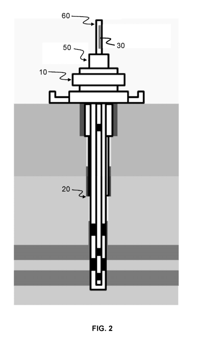
2
Christmas tree tool so that wire tools (slickline tools), cable tools, also
called
wireline tools, or flexitube tools, also called coiled tubing tools are
lowered inside
the riser. These tools carry out the maintenance operations in the well.
[0009] The
main problem of this approach is the cost, since the daily
rates for the rigs are quite high, especially in the offshore environment.
Furthermore, for carrying out these interventions it is necessary to wait
until the rig
is available, something that may take months, so that from the fault to the
repair,
these wells are kept closed or with reduced production, which may generate a
relatively high loss of production in high-productivity wells.
[00010] In an attempt to solve the problem described above, document
W02011159563A2 provides a system for carrying out underwater operations. The
system comprises service apparatus supported on a floating unit, dispensing
with
the need for a rig for service operations in subsea wells. However, there will
still be
dependence on a floating vessel throughout the workover operation in the well.
[0010] In order to eliminate the need for any vessel dedicated to the
workover operation throughout its duration, resident autonomous robots are
used
in the wells for carrying out the necessary maintenance operations. The robot
remains inside the well throughout its useful life, and is only removed or
replaced
in case of breakdown. Document US637862781, for example, discloses
autonomous equipment for oil wells comprising (a) a body to be positioned in a
well; (b) a source of electric power; (c) at least one sensor for monitoring
at least
one parameter; (d) a microprocessor receiving data from the sensor; (e) a
memory
connected to the microprocessor; (f) a transport mechanism controlled by the
microprocessor for moving the body of the equipment inside the well; (g) a
working
end for carrying out operations inside the well. The autonomous equipment is
controlled remotely for performing the maintenance tasks or data collection
inside
the well.
[0011]
However, since the equipment in document US6378627B1 is
permanently resident in the wells, it is necessary for each well to have its
own
robot, meaning that the costs are high, compared to the use of rigs for the
interventions.
[0012] As
will be presented in more detail below, the present invention
aims to solve the problems of the prior art described above in a practical and
efficient manner.
CA 03069497 2020-01-09
WO 2019/012294
PCT/GB2018/052000
3
SUMMARY OF THE INVENTION
[0013] The
present disclosure aims to provide methods of inserting and
removing a device in a subsea oil well that dispenses with the need for a rig
dedicated to this service.
[0014] Also disclosed are methods of inserting and removing a device,
such as an autonomous device, in a subsea oil well so as to enable one and the
same device to perform maintenance tasks in different subsea oil wells,
dispensing with the need for a device resident inside the well.
[0015] The
present disclosure provides a method of inserting a device,
such as an autonomous device, in a subsea oil well, said method comprising the
steps of (i) removing a protective cap from a wet Christmas tree (WCT)
assembly,
(ii) inserting a WCT tool in the place where the protective cap was previously
coupled, wherein the WCT tool is connected to a receptacle comprising within
it
the device and (iii) opening at least one of receptacle and WCT tool so as to
release the autonomous device into the subsea oil well.
[0016]
Optionally, the receptacle comprises a shape corresponding to the
shape of the device.
[0017]
Optionally, at least one of the receptacle and the WCT tool is
configured for being opened and closed.
[0018] Optionally the method further comprises the step of transporting a
combination of the WCT tool and the receptacle comprising the device between
the sea surface and the sea bed by means of a support vessel and/or a ROV.
[0019]
Optionally the method further comprises removing the WCT tool
from the WCT assembly after the device is released into the subsea oil well.
[0020] Optionally, the method comprises replacing the protective cap on
the the WCT assembly after WCT tool has been removed.
[0021]
Optionally, both the receptacle and the WCT tool are configured to
be opened and closed, and wherein the step of opening comprises opening both
the receptacle and the WCT tool.
[0022] In addition, the present disclosure provides a method for removing
a device, such as an autonomous device, from a subsea oil well, said method
comprising the steps of (i) removing a protective cap from a wet Christmas
tree
(WCT) assembly, (ii) inserting a WCT tool in the place where the protective
cap
CA 03069497 2020-01-09
WO 2019/012294
PCT/GB2018/052000
4
was previously coupled, wherein the WCT tool is connected to a receptacle
suitable for receiving within it the device and (iii) guiding the autonomous
device
from inside the subsea oil well to the receptacle.
[0023]
Optionally, the receptacle comprises a shape corresponding to the
shape of the device.
[0024]
Optionally, at least one of receptacle and WCT tool is configured
for being opened and closed.
[0025]
Optionally, the method further comprises the step of transporting a
combination of the WCT tool and the receptacle comprising the device between
the sea surface and the sea bed by means of a support vessel and/or a ROV.
[0026]
Optionally, the method further comprises the step of disconnecting
a combination of the WCT tool and the receptacle comprising the device from
the
WCT assembly.
[0027]
Moreover, the present disclosure provides a system for insertion
and removal of a device, such as an autonomous device, in a subsea oil well,
said
system comprising (i) a WCT assembly comprising a removable protective cap
and (ii) a WCT tool connected to a receptacle comprising within it the device,
wherein the WCT tool is suitable for being inserted in the place where the
protective cap is coupled, wherein at least one of the receptacle and the WCT
tool
is able to be opened or closed, to release the device into the subsea oil well
or to
retain the device inside the receptacle.
[0028]
Optionally the device comprises at least one set of expandable
arms.
[0029]
Optionally, the device comprises a central body and four sets of
expandable arms, wherein two sets of expandable arms are positioned at a first
end of the central body, and two sets of expandable arms are positioned at a
second end of the central body.
[0030]
Optionally, each set of expandable arms comprises three
expandable arms.
[0031] Optionally, each expandable arm is configured as an elastic body
of the spring type.
[0032]
Optionally, each expandable arm comprises two elastic elements
joined together at a central point.
CA 03069497 2020-01-09
WO 2019/012294
PCT/GB2018/052000
[0033] Optionally, a sliding wheel is positioned at the central
point.
[0034] Optionally, the system further comprises a support for the
sliding
wheel, and wherein the elastic elements are fixed to the support.
[0035] Optionally, each elastic element comprises a spring element
with
5 .. double kink and straight middle.
[0036] Optionally, the sliding wheels are positioned to be inclined
relative
to an axis of motion of the device.
[0037] Optionally, the inclined wheels are configured to produce a
helicoidal or bi-helicoidal motion of the device inside the subsea oil well.
[0038] There is also disclosed an apparatus for use during insertion of a
device in a subsea oil well via a wet Christmas tree (WCT) assembly comprising
a
removable protective cap, or during removal of the device therefrom, the
apparatus comprising: a WCT tool configured to be inserted in the place where
the
protective cap of the WCT assembly is coupled, and a receptacle, connected to
the WCT tool, for storing the autonomous device, wherein at least one of
receptacle and WCT tool is able to be opened or closed, to release the device
into
the subsea oil well or to retain the WCT tool inside the receptacle.
[0039] According to a first aspect there is a method of inserting
an
autonomous device (30) in a subsea oil well (20), characterized in that it
comprises the steps of: removing a protective cap (40) from a WCT assembly
(10);
inserting a WCT tool (50) in the place where the protective cap (40) was
previously
coupled, wherein the WCT tool (50) is connected to a receptacle (60)
comprising
within it the autonomous device (30); and opening at least one of receptacle
(60)
and WCT tool (50) so as to release the autonomous device (30) into the subsea
oil
well (20).
[0040] According to a second aspect there is a method according to
the
first aspect, characterized in that the receptacle (60) comprises a shape
corresponding to the shape of the autonomous device (30).
[0041] According to a second aspect there is a method according to
the
first or second aspect, characterized in that at least one of receptacle (60)
and
WCT tool (50) is configured for being opened and closed.
[0042] According to a second aspect there is a method according to
any
one of the first to third aspects, characterized in that it additionally
comprises the
CA 03069497 2020-01-09
WO 2019/012294
PCT/GB2018/052000
6
step of transporting the assembly formed by the WCT tool (50) and the
receptacle
(60) comprising the autonomous device (30) between the sea surface and the sea
bed by means of at least one of support vessel and ROV.
[0043]
According to a fifth aspect there is a method of removing an
autonomous device (30) from a subsea oil well (20), characterized in that it
comprises the steps of: removing a protective cap (40) of a WCT assembly (10);
inserting a WCT tool (50) in the place where the protective cap (40) was
previously
coupled, wherein the WCT tool (50) is connected to a receptacle (60) suitable
for
receiving within it the autonomous device (30); and guiding the autonomous
device (30) from inside the subsea oil well (20) to the receptacle (60).
[0044]
According to a sixth aspect there is a method according to the fifth
aspect, characterized in that the receptacle (60) comprises a shape
corresponding
to the shape of the autonomous device (30).
[0045]
According to a seventh aspect there is a method according to the
fifth or sixth aspect, characterized in that at least one of receptacle (60)
and WCT
tool (50) is configured for being opened and closed.
[0046]
According to an eighth aspect there is a method according to any
of the fifth to seventh aspects, characterized in that it additionally
comprises the
step of transporting the assembly formed by the WCT tool (50) and by the
receptacle (60) comprising the autonomous device (30) between the sea surface
and the sea bed by means of at least one of support vessel and ROV.
[0047]
According to a ninth aspect there is a method according to any of
the fifth to eighth aspects, characterized in that it additionally comprises
the step of
disconnecting the assembly formed by the WCT tool (50) and the receptacle (60)
comprising the autonomous device (30) from the WCT assembly (10).
[0048]
According to a tenth aspect there is a system for insertion and
removal of an autonomous device (30) in a subsea oil well (20), characterized
in
that it comprises: a WCT assembly (10) comprising a removable protective cap
(40); and a WCT tool (50) connected to a receptacle (60) comprising within it
the
autonomous device (30), wherein the WCT tool (50) is suitable for being
inserted
in the place where the protective cap (40) is coupled, wherein at least one of
receptacle (60) and WCT tool (50) is able to be opened or closed, releasing
the
autonomous device (30) into the subsea oil well (20) or retaining same inside
the
receptacle (60).
CA 03069497 2020-01-09
WO 2019/012294
PCT/GB2018/052000
7
[0049] According to
an eleventh aspect there is a system according to the
tenth aspect, characterized in that the autonomous device (30) comprises at
least
one set (9) of expandable arms (1), wherein each set (9) of expandable arms
(1)
comprises three expandable arms (1).
[0050] According to a
twelfth aspect there is a system according to the
tenth or eleventh aspect, characterized in that it comprises four sets (9) of
expandable arms (1) each with three expandable arms (1), wherein two sets (9)
of
expandable arms (1) are positioned before a central body (5), and two sets (9)
of
expandable arms (1) are positioned after the tool (5).
[0051] According to a
thirteenth aspect there is a system according to the
eleventh or twelfth aspect, characterized in that the expandable arm (1) is an
elastic element of the spring type.
[0052] According to a
fourteenth aspect there is a system according to
any one of the eleventh to thirteenth aspects, characterized in that the
expandable
arm comprises two elastic elements (11) joined together at a central point,
wherein
a sliding wheel (2) is positioned at the central point.
[0053] According to a
fifteenth aspect there is a system according to the
fourteenth aspect, characterized in that it comprises a support (3) for the
sliding
wheel (2), wherein the elastic elements (11) are fixed to the support (3).
[0054] According to a
sixteenth aspect there is a system according to the
fourteenth or fifteenth aspect, characterized in that each elastic element
(11)
comprises a spring element with double kink and straight middle.
[0055] According to a
seventeenth aspect there is a system according to
any one of the fourteenth to sixteenth aspects, characterized in that the
sliding
wheels (2) are
positioned so that they are inclined relative to an axis of motion of
the autonomous device (30), wherein the inclined wheels are configured for
producing a helicoidal or bi-helicoidal motion of the autonomous device (30)
inside
the subsea oil well (20).
BRIEF DESCRIPTION OF THE FIGURES
[0056] The detailed
description presented hereunder refers to the
appended figures and their respective reference numbers.
[0057] Fig. 1 shows a
sectional view of a WCT assembly and of a subsea
oil well where the methods according to the preferred embodiment are applied.
CA 03069497 2020-01-09
WO 2019/012294
PCT/GB2018/052000
8
[0058] Fig. 2 shows the view in Fig. 1 additionally showing a WCT
tool
connected to a receptacle comprising within it an autonomous device.
[0059] Fig. 3 shows a preferred configuration of the autonomous
device.
[0060] Fig. 4 shows an isolated view of an expandable arm according
to
an optional configuration of an autonomous device.
DETAILED DESCRIPTION OF THE INVENTION
[0061] To begin with, it is emphasized that the following
description is
based on a preferred embodiment. However, as will be obvious to a person
skilled
in the art, the invention is not limited to this particular embodiment.
[0062] Fig. 1 shows a sectional view of a wet Christmas tree (WCT)
assembly 10 and of a subsea oil well 20 where the methods according to the
preferred embodiment are applied.
[0063] Firstly, a method of inserting a device, such as an
autonomous
device 30, in the subsea oil well 20 is provided. A first step of the method
according to the preferred embodiment consists of removing a protective cap 40
(known as tree cap) from the WCT assembly 10.
[0064] In a second step of the method of insertion, a WCT tool 50
(known as tree running tool), or some other equivalent interface tool, is
inserted in
the place where the protective cap 40 was previously coupled. The insertion of
the
WCT tool 50 may comprise coupling the WCT tool 50 to the WCT assembly 10 in
the same way that the protective cap 40 was coupled.
[0065] Preferably, the WCT tool 50 is connected to a receptacle 60
suitable for receiving within it the autonomous device 30. Preferably, the
receptacle 60 comprises a shape corresponding to the shape of the autonomous
device 30. In the example shown in Fig. 2 the receptacle 60 and the autonomous
device 30 have an elongated shape.
[0066] Preferably, the receptacle 60 is able to be opened and
closed.
More preferably, the bottom end of the receptacle 60 is a closable opening
through
which the autonomous device 30 passes.
[0067] Optionally, the WCT tool 50 is able to be opened and closed,
allowing or not allowing passage of the autonomous device 30.
[0068] In a third step of the method of insertion, the receptacle
60
and/or WCT tool 50 is opened so as to release the autonomous device 30 into
the
CA 03069497 2020-01-09
WO 2019/012294
PCT/GB2018/052000
9
subsea oil well 20. If both the receptacle 60 and the WCT tool 50 are able to
be
opened and closed, then both can be opened in this step.
[0069] Once
the device 30 has been released, it may be preferable to
remove the WCT tool 50 and to replace the protective cap 40.
[0070] There is further provided a method of removing a device, such as
the autonomous device 30, from the subsea oil well 20. A first step of the
method
of removal according to the preferred embodiment also consists of removing the
protective cap 40 from the WCT assembly 10, assuming it has been replaced
after
the device was introduced. If the WCT tool 50 with the associated receptacle
60 is
still attached, this step and the second step mentioned below may be omitted.
[0071] In a
second step of the method of removal, the WCT tool 50 or
some other equivalent interface tool is inserted in the place where the
protective
cap 40 was previously coupled.
[0072]
Preferably, the WCT tool 50 is connected to the empty receptacle
60, which is suitable for receiving within it the autonomous device 30.
[0073]
Finally, the device 30 is guided from inside the subsea oil well 20
to the receptacle 60. If the device is fully autonomous, the step of guiding
may
happen automatically (i.e. the device 30 may guide itself). Alternatively, the
device
30 may be remotely guided by an operator.
[0074] Optionally, the receptacle 60 is closed with the autonomous
device 30 inside it. Also optionally, the WCT tool 50 is closed, so as to
confine the
autonomous device 30 in the receptacle 60 even when the receptacle 60 itself
is
open.
[0075]
Preferably, the combination or assembly formed by the WCT
tool 50 and the receptacle 60 comprising the autonomous device 30 is
transported
between the sea surface and the sea bed by a support vessel and/or an ROV
(Remotely Operated Vehicle).
[0076]
There is further provided a system for insertion and removal of a
device such as an autonomous device 30 in the subsea oil well 20. The system
comprises a WCT assembly 10 comprising a removable protective cap 40 and a
WCT tool 50 connected to a receptacle 60 comprising within it the autonomous
device 30, wherein the WCT tool 50 is suitable for being inserted in the place
where the protective cap 40 is coupled.
[0077] In
the present system, at least one of receptacle 60 and WCT tool
CA 03069497 2020-01-09
WO 2019/012294
PCT/GB2018/052000
50 is able to be opened or closed, releasing the autonomous device 30 into the
subsea oil well 20 or retaining same inside the receptacle 60, depending on
the
method (insertion or removal) that is being executed.
[0078]
Preferably, the device is an autonomous device 30 such as an
5
autonomous robot suitable for performing workover operations inside the
subsea oil well 20, as illustrated in Fig. 3.
[0079] As
can be seen in Figs. 3 and 4, the autonomous device 30
comprises a central body 5 and expandable arms 1. Each expandable arm 1
comprises at least one sliding wheel 2 configured for touching the inside wall
of
10 a pipeline.
[0080]
Optionally, the autonomous device 30 comprises at least one set 9
of expandable arms I. Each set 9 can comprise three expandable arms 1, for
example. The configuration with three expandable arms 1 may be advantageous
through allowing better centring thereof, in comparison with other
configurations.
[0081] In any one of the configurations described, each expandable arm
1 comprises at least one sliding wheel 2 configured for touching the inside
wall of
the pipeline. In this way, when a configuration with three expandable arms 1
is
adopted, three sliding wheels 2 will be adopted, i.e. one for each expandable
arm.
[0082] In
alternative configurations (not shown in the figures) only one set
9 of expandable arms 1 may be adopted. This may be achieved by providing a
central body 5 enclosed by the expandable arms 1. In these configurations,
three
expandable arms 1 are preferably adopted.
[0083] Fig.
4 shows an isolated view of an expandable arm 1 according
to an optional configuration; in this configuration, the expandable arm 1 is
an
elastic body of the spring type. More particularly, the expandable arm 1
comprises two elastic elements 11 joined together at a central point. A
sliding
wheel 2 can be positioned at the central point. In this configuration, a
support 3
for the sliding wheel 2 may also be adopted, wherein the expandable arms 1
would be fixed to the support 3.
[0084] In this optional configuration, it can be seen that each elastic
element 11 comprises a spring element (of the spring assembly type) with
double
kink and straight middle. In other words, the elastic element 11 is made from
a
flexible material that can be compressed and then spring back to its original
shape. It is thus possible to achieve a configuration whose profile is reduced
to
CA 03069497 2020-01-09
WO 2019/012294
PCT/GB2018/052000
11
comprise a larger range of diameters.
[0085]
Optionally, the sliding wheels 2 are positioned so that they are
inclined relative to the axis of motion of the central body 5 (or, in use, the
central
axis of the pipeline), so as to produce a helicoidal motion inside the
pipeline.
[0086] In optional configurations, as shown in Fig. 3, in which four sets 9
of expandable arms 1 are adopted, e.g. with each set 9 having three arms 1,
two
sets 9 can be positioned before the central body 5 and two sets 9 can be
positioned after the central body 5. In these configurations, all the sliding
wheels 2
may be inclined, providing two sets 9 of inclined wheels, both in the front
portion
and in the rear portion. The central body 5 then follows a bi-helicoidal path
as it
moves through the pipeline, meaning that its traction capacity is twice as
great as
that of a conventional robot that performs a helicoidal motion.
[0087] In
this optional configuration, the sets 9 with three expandable
arms 1 are joined at the ends of the expandable arms 1 by connecting elements.
These elements may be any known connecting elements.
[0088] In
addition, a linkage 4 may be adopted, connecting together (at
each end) the set 9 of expandable arms 1 closest to the central body 5 to the
set 9
further away from the central body 5. This linkage 4 may be rigid or flexible,
so as
to allow rotational and bending movements.
[0089] Thus, there are provided methods and a system that dispense with
the need for a dedicated rig for this service. In addition, since the device
30 is not
resident, it is able to perform maintenance tasks in different subsea oil
wells in a
practical manner and at low cost.
[0090]
Countless variations falling within the scope of protection of the
present application are permitted. This reinforces the fact that the present
invention is not limited to the configurations/particular embodiments
described
above. As such, modifications of the above-described apparatuses and methods,
combinations between different variations as practicable, and variations of
aspects
of the invention that are obvious to those of skill in the art are intended to
be within
the spirit and scope of the claims.