Note: Descriptions are shown in the official language in which they were submitted.
CA 03069536 2020-01-09
WO 2019/018397
PCT/US2018/042489
Method for Optimization of Orthopedic Component Design
CROSS-REFERENCES TO RELATED APPLICATIONS
[0001] This application claims the benefit of U.S. Provisional Patent
Application
Serial No. 62/533,203 filed on July 17, 2017 and entitled "Method for
Optimization of
Periprosthetic and Humeral Component Design," which is incorporated by
reference
in its entirety for all purposes.
STATEMENT REGARDING FEDERALLY SPONSORED RESEARCH
[0002] Not Applicable.
BACKGROUND OF THE INVENTION
1. Field of the Invention
[0003] The invention relates to a method for modeling the humeral anatomy
that
facilitates the design of product offerings for shoulder and elbow surgery,
manufacturing a periprosthetic implant for repairing a part of a bone in a
subject, and
a method for the optimization of periprosthetic bone plates and intramedullary
nails
through the use of medical imaging data from upper extremity periprosthetic
fractures.
2. Description of the Related Art
[0004] There has been a dramatic growth in the number of fractures
worldwide
with an aging population and proliferation of motor vehicles. There has also
been
increased patient expectation in regard to function and outcome after
sustaining a
fracture. Together, these factors have dramatically driven more operative
intervention for fractures worldwide. However, current designs of plates and
intra-
medullary nails are not anatomic in shape and the sizes available are not
based on
an anatomic distribution.
[0005] There is a range of complications in fracture treatment
associated with
trauma fixation devices that are not anatomically correct. This includes
further
fracturing the bone when trying to place an intramedullary device that is not
in an
anatomic shape as well as catastrophic early failure when contact with native
bone is
not optimized. When looking at plates, current plating systems do not provide
for an
anatomic offering. For example, all of the proximal and distal humeral plates
currently on the market have only one plate width. This results in a plate
that is too
1
CA 03069536 2020-01-09
WO 2019/018397
PCT/US2018/042489
wide in a significant percentage of the population resulting in soft tissue
irritation due
to plate overhang. In addition, this results in a plate that is too small in
many patients
thereby failing to maximize bony fixation and increasing the risk of failure.
The rapid
growth of international markets with patients representing a spectrum of
patient sizes
has exacerbated this problem.
[0006] Along with the dramatic increase of joint replacements
worldwide, there
has been an increase incidence of periprosthetic fractures around these
implants.
Treatment of these fractures is difficult due to the fact that the medullary
canal can be
filled with an arthroplasty stem making fixation challenging. In addition to
fractures
around arthroplasty components, similar challenges can occur when fractures
occur
around intramedullary nails.
[0007] In regard to shoulder and elbow arthroplasty, there has also
been a rapid
increase in the number of product offerings with different humeral stem
lengths. In
addition to different stem lengths, there are cemented as well as uncemented
options
for stem fixation. These factors have resulted in different fracture patterns,
which
were previously not well understood.
[0008] In the past, some companies have designed trauma devices by
simply
overlaying a design over imaging of cadaveric specimens rather than developing
a
true scientific basis and anatomic rationale for the shape and size
distribution of
plates and intramedullary devices. In the past, this design process was based
on a
"best fit" leaving a significant proportion of the population on either side
of a bell
shape curve with an implant that is either too big or too small.
[0009] Current designs of plates and intra-medullary nails are not
anatomic in
shape and the sizes available are not based on an anatomic distribution. While
plates have been specifically designed for use for treatment of lower
extremity
periprosthetic fractures, there are no fixation systems designed specifically
for the
upper extremity periprosthetic fractures. Secure fixation with current non-
anatomic
plates can be very challenging due to inappropriate plate shape, plate length,
and
screw hole positions that are not optimized to capture the remaining bone.
Lower
extremity periprosthetic plates tend to be much larger and not-anatomically
correct
for the upper extremity. Use of these larger lower extremity plates for the
upper
2
CA 03069536 2020-01-09
WO 2019/018397
PCT/US2018/042489
extremity can necessitate increased soft tissue stripping which can impact
healing.
Moreover, the use of plates that are not anatomically correct and do not fit
correctly
can result in impingement on soft tissues and prominence leading to patient
discomfort with the need for additional revision surgery.
[0010] Therefore, there exists a need for a methodology to improve
understanding
of periprosthetic fractures and the associated humeral anatomy to facilitate
the
design and selection of anatomically correct periprosthetic bone plates.
SUMMARY OF THE INVENTION
[0011] The humerus is not straight and the use of non-anatomically
correct
devices can result in catastrophic early device loosening when contact with
native
bone is not optimized, iatrogenic humeral fractures, and increased risk of
future
fractures due to stress risers. The present invention addresses the foregoing
needs
by providing methods to improve understanding of the associated humeral
anatomy.
This methodology describes the interaction of anatomical features of the
humerus
and how these features change based on the specific location in the humerus.
Additionally, the methodology has demonstrated that the shape of the humerus
is
side specific. Therefore, having right and left specific devices with an
anatomic
shape in a true population based distribution may further facilitate and
improve
device design. The methodology can optimize loading and fit at the bone-device
interface. This methodology can be used to facilitate the design of total and
partial
elbow arthroplasty, intramedullary nails for the humerus, revision length
stems for
shoulder arthroplasty, plates for periprosthetic humeral fractures, mid-shaft
humeral
fractures and distal humeral fractures. The methodology and associated data
set can
further help define the appropriate size, shape, distribution of product
offerings for
these devices.
[0012] In addition to understanding the associated humeral anatomy,
studying and
analysis of periprosthetic fractures may facilitate the design and selection
of
anatomically correct periprosthetic bone plates.
[0013] In one aspect, the disclosure provides a method where improved
understanding of humeral anatomy is gained through the use of CT scan data and
3D
modeling. Whereas previous reports noted the potential bending of the humerus
in
3
CA 03069536 2020-01-09
WO 2019/018397
PCT/US2018/042489
one plane, the current methodology notes that the humeral anatomy has a
specific
three dimensional architecture. The methodology, therefore, can facilitate the
design
of anatomically correct implants that minimize potential complications.
[0014] In one configuration, a device is provided for treating a
fracture in a bone of
a subject. The device includes a first section having a first longitudinal
axis and a
second section having a second longitudinal axis. The first section is
connected to
the second section at a first junction between the first section and the
second
section. The first longitudinal axis and the second longitudinal axis form an
oblique
angle at the junction and the second section has a terminal end section having
a
width greater than the first section. The first section and the second section
of the
device may be configured to provide fixation to a region of the bone and
includes a
plurality of screw holes.
[0015] In some configurations of the device, the bone is the humerus
and the
second end section is adapted to conform to an outer surface of a proximal end
section of the bone. A perimeter of the terminal end of the second section may
be
dimensioned to conform to a greater tuberosity of the proximal end section of
the
humerus. The oblique angle formed at the junction may be configured to match
an
angle of a greater tuberosity from a centerline of the humerus. A length of
the device
may also be determined by a length of the humerus.
[0016] In some configurations of the device, a width of the first section
is
configured to provide fixation for a fracture in the bone. A plurality of
screw holes
may be provided on the device and the number of screw holes may be correlated
to
the width of the terminal end of the second section. The device may also be
configured to be specific for a left and a right side of the subject.
[0017] In some configuration, the device further includes a third section
having a
third longitudinal axis. The first section is connected to the third section
at a second
junction line between the first section and the third section. The first
longitudinal axis
and the third longitudinal axis may form an oblique angle at the second
junction.
[0018] In some configurations, the bone is the humerus and the second
end
section is adapted to conform to an outer surface of a distal end section of
the bone.
A perimeter of the terminal end of the second section may be dimensioned to
4
CA 03069536 2020-01-09
WO 2019/018397
PCT/US2018/042489
conform to a condyle of the distal end section of the humerus. The oblique
angle
formed at the first junction may be configured to match an angle of a condyle
from a
centerline of the humerus. The oblique angle formed at the second junction may
be
configured to match an angle of a condyle from a centerline of the humerus. A
length
of the device may be determined by a length of the humerus. A length of the
third
section may be configured to provide fixation for a fracture in the bone.
[0019] In one configuration, a device for treating a fracture in a
bone is provided.
The device includes a first section having a first longitudinal axis and a
second
section having a second longitudinal axis. The first section is connected to
the
second section at a first junction between the first section and the second
section.
The first junction forms a transition portion dimensioned to provide a
curvature
connecting the first section to the second section.
[0020] In some configurations, the location of the first junction is
determined by a
location of greatest deviation from a straight centerline of the bone. The
first section
has a length that may be greater than a length of the second section.
[0021] In some configurations, the device may include an
intramedullary (IM) nail
and the bone may be a humerus. The location of the first junction may be
between
60-90 percent of the length of the humerus. The location of the first junction
may
also be at 80 percent of the length of the humerus.
[0022] In some configurations, the device includes a third section having a
third
longitudinal axis. The second section is connected to the third section at a
second
junction between the second section and the third section. The second junction
forms a transition portion dimensioned to provide a curvature connecting the
second
section to the third section. The location of the second junction may be
determined
by a location of deviation from a straight centerline of the bone. The second
section
has a length that may be greater than a length of the third section and the
first
section. The device may be an intramedullary (IM) nail and the bone is a
humerus.
When the bone is the humerus, the location of the second junction may be
between
10-30 percent of the length of the humerus or may be at 20 percent of the
length of
the humerus.
[0023] In one configuration, a method is provided for manufacturing an
orthopedic
5
CA 03069536 2020-01-09
WO 2019/018397
PCT/US2018/042489
implant for repairing a part of a bone in a subject. The method includes
forming the
implant to include at least one bend wherein the at least one bend corresponds
to an
anatomic shape. The anatomic shape may be determined by a number of steps,
which may include: i) obtaining an image of the bone from at least one viewing
plane;
ii) orienting on the image a first reference line indicating a maximum width
of a
feature of the bone from a first border of the bone to an opposite second
border of
the bone; iii) orienting on the image a second reference line perpendicular to
the first
reference line and extending from a midpoint of the first reference line to an
edge of
the bone indicating a length of the feature of the bone; iv) orienting on the
image a
third reference line indicating a length from a centerline of the bone to the
midpoint of
the first reference line; v) determining an angle between the third reference
line and
the second reference line to determine the at least one bend of the implant.
[0024] In some configurations, the method includes where the implant
is at least
one of a periprosthetic bone plate, a proximal humeral plate, a distal humeral
plate, a
humeral nail, or a humeral stem. The centerline used in the method may be: 1)
a line
with a constant equal distance between the first border and the second border
of the
bone, which are cortical bone borders; or 2) a line with a constant equal
distance
between the first border and the second border of the bone, which are cancel
bus
bone borders, or 3) a straight longitudinal bone axis centerline.
[0025] In some configurations, the bone used in the method is the humerus.
When the bone is the humerus, the feature may be a greater tuberosity, and the
first
reference line indicates a width of the greater tuberosity on the humerus. One
bend
of the implant may correspond to an angle of a greater tuberosity from the
centerline
of the humerus. In some configurations when the bone is the humerus, the
feature is
a condyle, and the first reference line indicates a width of the condyle on
the
humerus. One bend of the implant may correspond to an angle of the condyle
from
the centerline of the humerus.
[0026] In some configurations, the bone used in the method may be the
femur,
tibia, radius, or the ulna. The image used in the method may be a computed
tomography scan slice. In some configurations, the method includes determining
a
thickness of the bone to determine a screw hole location on the implant. The
method
6
CA 03069536 2020-01-09
WO 2019/018397
PCT/US2018/042489
may be automated, such that images are sent to a control system having a
processor
configured to execute a program stored thereon to automatically extract
measurements of the bone of the subject. The automated measurements of the
bone may be referenced to manufacture a plate using an additive manufacturing
system.
[0027] In one configuration, a method is provided for manufacturing an
orthopedic
implant for repairing a part of a bone in a subject. The method may include
forming
the implant to include at least two bends. The bends may correspond to an
anatomic
shape determined by: i) obtaining an image of the bone from at least one
viewing
plane; ii) orienting on the image a first reference line indicating a maximum
width of a
first feature of the bone from a first border of the bone to an opposite
second border
of the bone; iii) orienting on the image a second reference line indicating a
maximum
width of a second feature of the bone from a first border of the bone to an
opposite
second border of the bone; iv) orienting on the image a third reference line
perpendicular to the first reference line and extending from a midpoint of the
first
reference line to a midpoint of the second reference line; v) orienting on the
image a
fourth reference line perpendicular to the second reference line and extending
from a
midpoint of the second reference line to an edge of the bone indicating a
length of the
second feature of the bone; vi) orienting on the image a fifth reference line
indicating
a length from a centerline of the bone to the midpoint of the first reference
line; vii)
determining an angle between the third reference line and the fourth reference
line to
determine at least one bend of the implant; and viii) determining an angle
between
the third reference line and the fifth reference line to determine at least
one bend of
the implant.
[0028] In some configurations, the method includes when the feature is a
condyle
of a humerus, and the first reference line indicates a width of the condyle on
the
humerus at an olecranon fossa. The second reference line may then indicate a
maximum width of the condyle.
[0029] In one configuration, a method is provided for manufacturing an
orthopedic
implant for repairing a part of a bone in a subject. The method includes
forming the
implant to include at least one bend where the bend corresponds to an anatomic
7
CA 03069536 2020-01-09
WO 2019/018397
PCT/US2018/042489
shape determined by: i) obtaining an image of the bone from at least one
viewing
plane; ii) orienting on the image a first reference line indicating a maximum
width of a
feature of the bone from a first border of the bone to an opposite second
border of
the bone; iii) orienting on the image a second reference line perpendicular to
the first
reference line and extending from a midpoint of the first reference line to a
centerline
of the bone indicating a length of the feature of the bone; and iv)
determining an
angle between the second reference line and the centerline to determine the at
least
one bend of the implant. In some configurations, the bone used in the method
is the
humerus. When the bone is the humerus, the feature may be a greater
tuberosity,
and the first reference line indicates a width of the greater tuberosity on
the humerus.
One bend of the implant may correspond to an angle of a greater tuberosity
from the
centerline of the humerus.
[0030] In one aspect, the disclosure provides a method for
manufacturing a
periprosthetic implant for repairing a part of a bone in a subject. The method
can
comprise forming the periprosthetic implant to include at least one curved
surface, a
contour of the at least one curved surface corresponds to an anatomic shape.
The
anatomic shape can be determined by a number of steps which may include (i)
obtaining an image of the bone from at least one viewing plane, where viewing
planes may include sagittal, coronal, and axial viewing planes. (ii) orienting
on the
image a proximal aspect line that extends from a first border of the bone to
an
opposite second border of the bone, (iii) orienting on the image a
longitudinal bone
axis extending from the proximal aspect line along a length of the bone
between the
first border and second border, (iv) orienting on the image a plurality of
lateral lines at
different distances from the proximal aspect line, each of the plurality of
lateral lines
extending perpendicularly from one of a plurality of first intersection points
on the first
border of the bone to one of a plurality of second intersection points
intersecting the
longitudinal bone axis at one of a plurality of second intersection points,
and (v)
extrapolating the anatomic shape based on the plurality of first intersection
points and
the plurality of second intersection points.
[0031] In some aspects, the periprosthetic implant can be a periprosthetic
bone
plate. The plurality of lateral lines can be placed at equidistant intervals
distally from
8
CA 03069536 2020-01-09
WO 2019/018397
PCT/US2018/042489
the proximal aspect line, or from a bone cut line. The equidistant interval
can be in a
range of 0.1 to 50 millimeters.
[0032] In some aspects, the bone can be the humerus. In other aspects,
the bone
can be the radius, the ulna, or any other bone.
[0033] In some aspects, the image can be a computed tomography scan slice.
Step (v) can further comprise measuring a first reference distance of a first
line of the
at least three lateral lines, the first line extending perpendicularly from a
first point of
the plurality of first intersection points to a first point of the plurality
of second
intersection points; measuring a second reference distance of a second line of
the at
least three lateral lines, the second line extending perpendicularly from a
second
point of the plurality of first intersection points to a second point of the
plurality of
second intersection points; measuring a third reference distance of a third
line of the
at least three lateral lines, the third line extending perpendicularly from a
third point of
the plurality of first intersection points to a third point of the plurality
of second
intersection points; and extrapolating the anatomic shape of the first border
based on
the first reference distance, the second reference distance, and the third
reference
distance.
[0034] In some aspects, step (v) can further comprise: extrapolating a
first
curvature of the anatomic shape between the first point of the plurality of
first
intersection points and the second point of the plurality of first
intersection points
based on the first reference distance and the second reference distance; and
extrapolating a second curvature of the anatomic shape between the second
point of
the plurality of first intersection points and the third point of the
plurality of first
intersection points based on the second reference distance and the third
reference
distance.
[0035] In some aspects, step (v) can further comprise extrapolating a
curvature of
the anatomic shape with data from the sagittal viewing plane, or extrapolating
a
curvature of the anatomic shape with data from the coronal viewing plane, or
extrapolating a curvature of the anatomic shape with data from the axial
viewing
plane. Any combination of one or more viewing planes may be used to determine
the
curvature of the anatomy, and the viewing planes used may be obtained at non-
9
CA 03069536 2020-01-09
WO 2019/018397
PCT/US2018/042489
orthogonal angles to each other.
[0036] In some aspects, the bone can include a periprosthetic
fracture. The
periprosthetic implant can be formed to fit the anatomic shape of the bone and
to
correct the periprosthetic fracture. The periprosthetic fracture can be
characterized
by (i) determining a length and width of a prosthetic stem, (ii) determining a
geometry
of the stem, (iii) determining a fixation of the stem, (iv) determining the
fracture
pattern, (v) determining if the fracture pattern is comminuted, (vi)
determining the
amount of angulation and displacement, and (vii) classifying the displacement.
The
periprosthetic implant can be formed having a length, width, and a shape, the
length,
width, and shape being determined by the characterized periprosthetic
fracture.
[0037] In another aspect, the disclosure provides a device for
treating a fracture
between a proximal section of a bone and a distal section of the bone wherein
the
proximal section of the bone has a prosthesis implanted therein for shoulder
arthroplasty, or where the distal section of the bone has a prosthesis
implanted
therein for elbow arthroplasty. The device comprises an elongated plate
dimensioned for placement on the bone across the fracture. The plate has a
bone
interface surface that faces the bone when the plate is placed on the bone
across the
fracture. In some embodiments, the bone interface surface has a shape that
transitions from a first curvature that is convex or concave at a proximal
portion of the
plate to a second curvature at a second portion of the plate longitudinally
adjacent to
the proximal portion of the plate. The second curvature is convex when the
first
curvature is concave, and the second curvature is concave when the first
curvature is
convex. The shape of the bone interface surface may transition from the second
curvature to a third curvature at a distal portion of the plate longitudinally
adjacent to
the second portion of the plate. The third curvature is convex when the second
curvature is concave, and the third curvature is concave when the second
curvature
is convex. The first curvature may be convex such that the second curvature is
concave and the third curvature is convex. One skilled in the art will
appreciate that
the shape of a plate may be defined by any number of curvature sections.
[0038] In some aspects, the plate can be a proximal humeral short
periprosthetic
plate formed for a short stem with a minimal distal fracture extension.
CA 03069536 2020-01-09
WO 2019/018397
PCT/US2018/042489
[0039] In some aspects, the plate can be a proximal humeral long
periprosthetic
plate formed for at least one of short stems with a distal fracture extension
and a
regular length stem with a minimal distal extension.
[0040] In some aspects, the plate can be a short distal humeral
periprosthetic
plate formed for a short humeral stem used with a total elbow arthroplasty,
with a
minimal proximal fracture extension.
[0041] In some aspects, the plate can be a long distal humeral
periprosthetic
plate, formed for a short humeral stem used with at least one of a total elbow
arthroplasty with a proximal humeral fracture extension and a regular length
humeral
stem used with a total elbow arthroplasty with a minimal proximal fracture
extension.
[0042] In some aspects, the plate can be a midshaft humeral
periprosthetic plate
formed for at least one of a regular length shoulder/humeral stems with a
minimal
fracture extension and a midshaft nonperiprosthetic fracture.
[0043] In some aspects, the plate can be a full-length periprosthetic
plate formed
for fractures that encompass a significant portion of the humerus, including
highly
comminuted fractures.
[0044] These and other features, aspects, and advantages of the
present
invention will become better understood upon consideration of the following
detailed
description, drawings, and appended claims.
BRIEF DESCRIPTION OF THE DRAWINGS
[0045] FIG. 1 is a cross-sectional view of one embodiment of a prior
art shoulder
prosthesis suitable for use in the present disclosure.
[0046] FIG. 2 shows a traced computed tomography (CT) two-dimensional
(2D)
CT slice in a coronal viewing plane of the humerus with measurement lines
shown in
dashed lines.
[0047] FIG. 2A shows a traced computed tomography (CT) two-dimensional
(2D)
CT slice in a coronal viewing plane of the humerus.
[0048] FIG. 2B shows a traced computed tomography (CT) two-dimensional
(2D)
CT slice in a sagittal viewing plane of the humerus with measurement lines
shown in
dashed lines.
[0049] FIG. 2C shows a traced computed tomography (CT) two-dimensional
(20)
11
CA 03069536 2020-01-09
WO 2019/018397
PCT/US2018/042489
CT slice in a sagittal viewing plane of the humerus.
[0050] FIG. 2D shows a coronal viewing plane of a humerus with
measurement
lines shown.
[0051] FIG. 2E shows an axial cross section of a humerus and a
depiction of the
cross section's location on an image of a humerus bone with measurement lines
shown.
[0052] FIG. 3A shows a sagittal view of a proximal section of a
humerus with
measurement lines shown.
[0053] FIG. 3B shows a sagittal view of a proximal section of a
humerus with
measurement lines shown.
[0054] FIG. 3C shows a proximal section of a humerus with measurement
lines
shown.
[0055] FIG. 3D shows a proximal section of a humerus with radius of
curvature
lines shown.
[0056] FIG. 4A shows a traced computed tomography (CT) two-dimensional (2D)
CT slice in an axial viewing plane of the humerus along the line 4A-4A in FIG.
2 with
a periprosthetic bone plate installed.
[0057] FIG. 4B shows a traced computed tomography (CT) two-dimensional
(2D)
CT slice in an axial viewing plane of the humerus along the line 4B-4B in FIG.
2 with
a periprosthetic bone plate installed.
[0058] FIG. 4C shows a traced computed tomography (CT) two-dimensional
(2D)
CT slice in an axial viewing plane of the humerus along the line 4C-4C in FIG.
2 with
a periprosthetic bone plate installed.
[0059] FIG. 4D shows a traced computed tomography (CT) two-dimensional
(2D)
CT slice in an axial viewing plane of the humerus along the line 4D-4D in FIG.
2 with
a periprosthetic bone plate installed.
[0060] FIG. 4E shows a traced computed tomography (CT) two-dimensional
(2D)
CT slice in an axial viewing plane of the humerus along the line 4E-4E in FIG.
2 with
a periprosthetic bone plate installed.
[0061] FIG. 4F shows a traced computed tomography (CT) two-dimensional (2D)
CT slice in an axial viewing plane of the humerus along the line 4F-4F in FIG.
2 with
12
CA 03069536 2020-01-09
WO 2019/018397
PCT/US2018/042489
a periprosthetic bone plate installed.
[0062] FIGs. 5A, 5B and 5C show one embodiment of a bone plate used
with a
shoulder prosthesis.
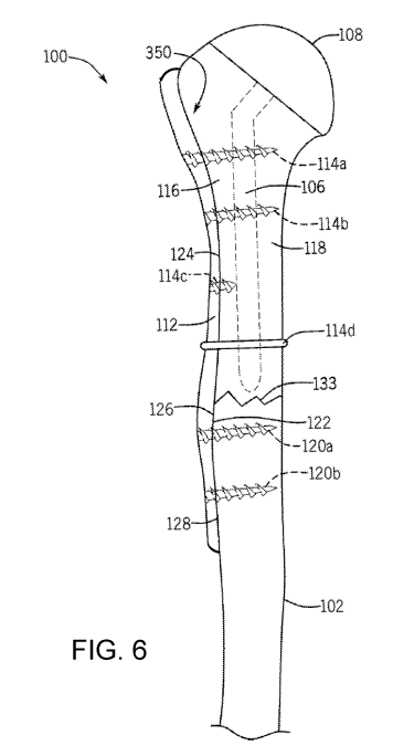
[0063] FIG. 6 shows one embodiment of a bone plate used with a
shoulder
prosthesis in a coronal (AP) viewing plane.
[0064] FIG. 7 shows one embodiment of a bone plate used with a
shoulder
prosthesis in a sagittal viewing plane.
[0065] FIG. 8 shows a perspective view of one embodiment of a
periprosthetic
bone plate.
[0066] FIG. 9A, 9B, 9C and 9D show a lateral condyle with measurement lines
shown.
[0067] FIG. 10A, 10B, and 10C show a posterior lateral condyle with
measurement lines shown.
[0068] FIGs. 11A, 11B, 11C and 11D show a medial condyle with
measurement
lines shown.
[0069] FIGs. 12A, 12B and 12C show a posterior medial condyle with
measurement lines shown.
[0070] FIGs. 13A, 13B, and 13C show embodiments of a lateral condyle
plate.
[0071] FIGs. 14A, 14B, and 14C show embodiments of a posterolateral
condyle
plate.
[0072] FIGs. 15A, 15B, and 15C show embodiments of a medial condyle
plate.
[0073] FIGs. 16A, 16B, and 16C show embodiments of a posteromedial
condyle
plate.
[0074] FIG 17 shows a graphical representation of averaged cancellous
centerline
offsets.
[0075] FIGs. 18A and 18B show embodiments of a humeral nail.
[0076] FIGs. 19A, 19B 19C and 19D show graphical representations of
width
measurements acquired for humeral bones.
[0077] Like reference numerals will be used to refer to like parts
from Figure to
Figure in the following description of the drawings.
DETAILED DESCRIPTION OF THE INVENTION
13
CA 03069536 2020-01-09
WO 2019/018397
PCT/US2018/042489
[0078] In one aspect of the present disclosure, a novel methodology to
improve
understanding of external and internal anatomy of bones through the use of CT
scan
data and 3D modeling is provided. A retrospective review was undertaken of the
largest consecutive series of shoulder and elbow periprosthetic fractures to
improve
understanding of periprosthetic fractures. This review further reinforced the
need as
well as benefit of a truly anatomic plating system that can be adaptable to
address
periprosthetic fractures. While the methodology is described in detail for the
humerus, this methodology is applicable to other bones including, but not
limited to
the femur, tibia, radius, ulna, vertebral bodies, etc. This methodology
describes the
interaction of anatomical features of the external and internal humerus and
how these
features change based on the specific location in the humerus. In one aspect
of the
present disclosure, in order to drive efficiency automated measurements were
performed and this automation may be applicable to any bone.
[0079] In one aspect of the present disclosure, plate and
intramedullary nail
models were created to test the methodology and the interaction of the
anatomic
features and their interdependence on each other. The models had specific
features
for improved anatomic fracture fixation for intramedullary nails as well as
plates. The
results of the testing validated that the methodology significantly improved
fit
compared to currently available designs. The methodology can optimize and
facilitate the design of truly anatomic trauma fixation devices in an anatomic
shape as
well as size distribution.
[0080] Looking first at FIG. 1, there is shown one example embodiment
of a prior
art anatomic total shoulder prosthesis 10. One skilled in the art will
appreciate that
other prostheses, such as reverse shoulder arthroplasty, hemi arthroplasty,
stemless
shoulder arthroplasty, resurfacing, elbow prostheses and the like may be
suitable for
use with the present disclosure. The upper portion of the humerus 12 is
replaced by
a humeral component 14 including a stem 16 that extends into a bore formed
within
the humerus 12. Typically, the stem 16 is fixed within the bore formed within
the
humerus 12. The stem 16 has a longitudinal stem axis S. A generally
hemispherical
head 18 is connected to the stem 16. The stem 16 can be monolithic with the
head
18, or the stem 16 and the head 18 can formed as separate parts. The
14
CA 03069536 2020-01-09
WO 2019/018397
PCT/US2018/042489
hemispherical head 18 has a base surface 19 and a longitudinal head axis H.
The
hemispherical head 18 of the humeral component 14 articulates with a
complementary concave section 22 of a glenoid component 24 that is fixed
within the
glenoid cavity of the scapula 26 (shown cutaway) using cemented or uncemented
posts 28. The glenoid component 24 includes a base surface 27 opposite the
concave section 22 that serves as an articular surface of the glenoid
component 24.
[0081] A unique database of fifty consecutive high resolution thin cut
two
dimensional and three dimensional CT scans of the entire humerus with a custom
designed bone stock protocol of patients who have undergone anatomic shoulder
arthroplasty was available for study. This custom designed protocol was
specifically
developed at the Mayo Clinic for a detailed understanding of the anatomy of
these
patients. In addition, 30 modeling of each of these patients was performed. A
method for understanding external and internal humeral anatomy was
subsequently
developed using this unique resource and underwent validation. This data set
facilitated developing a methodology to understand the humeral anatomy and
facilitate the design of anatomically correct plates and implants.
[0082] In non-limiting examples, the method facilitates the design of
total and
partial elbow arthroplasty, intramedullary nails for the humerus, revision
length stems
for shoulder arthroplasty, plates for periprosthetic humeral fractures, mid-
shaft
humeral fractures and distal humeral fractures.
[0083] Proper design and/or selection of a periprosthetic plate can be
achieved
using a method of this disclosure. The proper design and selection of a
periprosthetic
plate was facilitated by review of a large volume of upper extremity
prosthetic
replacements, specifically shoulder and elbow replacements. Patients with
periprosthetic humeral fractures around a shoulder arthroplasty or elbow
arthroplasty
were identified. This unique data set included 108 cases: 59 shoulder
arthroplasties
with periprosthetic humeral fractures and 49 elbow arthroplasties with
periprosthetic
humeral fractures. This data set facilitated understanding the specific
fracture
location, fracture pattern, and remaining bone stock. Accordingly, in one
aspect, a
method of designing and manufacturing a periprosthetic implant for repairing a
part of
a bone in a subject was developed. Specifically, a method for designing and
CA 03069536 2020-01-09
WO 2019/018397
PCT/US2018/042489
manufacturing a periprosthetic implant for periprosthetic fractures around
shoulder
arthroplasty and periprosthetic fractures around elbow arthroplasty was
developed.
Periprosthetic Fractures around Shoulder Arthroplasty
[0084] A
prosthetic implant present in a subject can be characterized by a number
of parameters. A length and width of a stem of the prosthetic implant can be
measured in millimeters. A geometry of the stem could be assessed as either
tapered or cylindrical. A fixation mechanism of the stem could be determined
to be
uncemented or cemented. An upper extremity fracture in a subject can have a
variety of patterns that can be assessed as one of the following: (1) greater
tuberosity
only; (2) type-A fractures are located at the tip of the prosthesis and extend
proximally; (3) type-B fractures lie at the tip of the prosthesis without
extension or
with only minimal extension proximally but can have a variable amount of
extension
distally; and (4) type-C fractures are located distal to the tip of the
prosthesis. The
fracture can also be determined as a comminuted or not comminuted fracture. It
is
also important to determine if the stem has become loose. The fracture pattern
can
be further characterized as transverse, oblique, or spiral, and amounts of
angulation
and displacement can also be assessed. Angulation was classified as mild (15
),
moderate (150 to 30 ), or severe (>30 ). Displacement was classified as mild
(within
one-third of the diameter of the humeral shaft), moderate (one-third to two-
thirds of
the diameter of the humeral shaft), or severe (beyond two-thirds of the
diameter of
the humeral shaft), or complete displacement. The greater tuberosity was
assessed
to determine if an adequate amount of bone was present in the greater
tuberosity for
screw fixation. Treatment was determined as surgical or non-surgical and
treatment
type was also determined. Table A displays the data for 59 shoulder
arthroplasties
with periprosthetic humeral fractures classified according to the above
criteria.
Table A
Humeral Stem Width Stem Geometry Stem Fixation Fracture Type
Comminuted
4 mm-8 mm (25) Taper (36) Uncemented Greater Tuberosity (6) Yes
(31)
(35)
9 mm-13 mm (22) Cylindrical (23) Cemented (24) Type A (17)
No (28)
14 mm-18 mm (12) Type B (22)
16
CA 03069536 2020-01-09
WO 2019/018397
PCT/US2018/042489
Type 0(13)
Humeral Stem Loose Fracture Pattern Fracture Displacement Bone Present
Anqulation for Fixation
Yes (9) Transverse (27) <15 (28) Within 1/3 diameter Yes
(43)
humeral shaft (24)
No (50) Oblique (23) 15-30 (14) 1/3 to 2/3
diameter No (16)
humeral shaft (9)
Spiral (9) >30 (17) Greater 2/3 diameter
humeral shaft (26)
Periprosthetic Fractures around Elbow Arthroplasty
[0085] A prosthetic implant present in a subject can be characterized
by a number
of parameters. A length and width of a stem of the prosthetic implant can be
measured in millimeters. A geometry of the stem could be assessed as either
tapered or cylindrical. A fixation mechanism of the stem could be determined
to be
uncemented or cemented. An upper extremity fracture in a subject can have a
variety of patterns that can be assessed as one of the following: (1) condylar
region
only; (2) type-A fractures are located at the tip of the prosthesis and extend
toward
distal humerus, (3) type-B fractures lie at the tip of the prosthesis without
extension
or with only minimal extension distally but can have a variable amount of
extension
proximally, and (4) type-C fractures are located proximal to the tip of the
prosthesis.
The fracture can also be determined as a comminuted or not comminuted
fracture. It
is also important to determine if the stem has become loose. The fracture
pattern
can be further characterized as transverse, oblique, or spiral, and amounts of
angulation and displacement can also be assessed. Angulation was classified as
mild (15 ), moderate (15 to 30 ), or severe (>30 ). Displacement was
classified as
mild (within one-third of the diameter of the humeral shaft), moderate (one-
third to
two-thirds of the diameter of the humeral shaft), or severe (beyond two-thirds
of the
diameter of the humeral shaft), or complete displacement. Treatment was
determined as surgical or non-surgical and treatment type was also determined.
Table B displays the data for 49 elbow arthroplasties with periprosthetic
humeral
17
CA 03069536 2020-01-09
WO 2019/018397
PCT/US2018/042489
fractures classified according to the above criteria.
Table B
Humeral Stem Lenath Stem Width Cement Fixation Fracture Type
Comminuted
70 mm-100 mm (31) 4 mm (6) Cemented (48) Condylar (1) No (26)
120 mm-150 mm (18) 6 mm (37) Uncemented (1) Type A (1) Yes (23)
8 mm (6) Type B (24)
Type C (23)
Stem Loose Fracture Pattern Anqulation Displacement
No (23) Transverse (14) <15 (7) Within 1/3
diameter
humeral shaft (7)
Yes (26) Oblique (25) 15-30 (15) 1/3 to 2/3 diameter
humeral shaft (13)
Spiral (10) >30 (27) Greater 2/3 diameter
humeral shaft (29)
Pre-Operative CT Scans
[0086] The methodology for facilitating the design and manufacturing of
anatomically correct plates and implants involves analysis of pre-operation
medical
imaging data, such as from computerized tomography (CT) scans, and may also
include the use of 3D models. In one aspect, a periprosthetic implant can be
formed
to include at least one curved surface that can have contours that correspond
to
anatomic shapes of the subject. A contour of the at least one curved surface
can
correspond to an anatomic shape having been determined during analysis of CT
scans of the subject.
[0087] Looking at FIG. 2, the anatomic shape can be determined by a
number of
steps. An image 40 of a bone 42 of a subject can be obtained, in some
embodiments the image 40 can be a CT image, in other embodiments the image can
be an X-ray image, an ultrasonic image, a magnetic resonance image (MRI), a
positron emission tomography (PET) image, or the like. The bone can be a
humerus.
In other embodiments the bone can be a radius, an ulna, a femur, a tibia, or
any
other bone. A bone cut line 46 can be oriented on the image 40 that can extend
from
a first border 48 of the bone 42 to an opposite second border 50 of the bone
42. In
18
CA 03069536 2020-01-09
WO 2019/018397
PCT/US2018/042489
some embodiments, the bone cut line 46 can be oriented angularly across a
region of
a humeral head of a subject. A longitudinal bone axis 54 can be oriented on
the
image 40. The longitudinal bone axis 54 may extend longitudinally from a
proximal
humeral aspect. In another embodiment, the longitudinal bone axis 54 may
extend
longitudinally from an intersection 41A of a proximal aspect line, such as
proximal
greater tuberosity line 44 with the bone cut line 46, where the proximal
greater
tuberosity line 44 is oriented on the image 40 by extending perpendicularly
from a
first intersection point 41B on the first border 48 of the bone 42 at the most
proximal
and lateral aspect of a greater tuberosity through a second intersection point
41A
where the proximal greater tuberosity line 44 intersects the bone cut line 46,
and
further extends to a third intersection point 41C on the second border 50 of
the bone
42. In some embodiments, the bone 42 can be the humerus. FIG. 2A shows one
embodiment where the longitudinal bone axis 54 can follow the centerline of
bone 42,
defined as being a constant equal distance between the first border 48 and the
second border 50. When bone axis 54 is the centerline of the bone 42, the
nonlinear
shape of the axis line 54 defines the radius of curvature for the bone 42,
which can
be assessed at various points along the length of the bone axis line 54. The
nonlinear shape of the axis line 54 can provide a number of different radii of
curvature. When bone axis 54 is the centerline, the intersection of axis line
54 with
proximal greater tuberosity line 44 may determine intersection point 41A. In
one non-
limiting example, a first radius of curvature can transition to a second
radius of
curvature, and the second radius of curvature can transition to a third radius
of
curvature. The first radius of curvature and the third radius of curvature can
be
concave, while the second radius of curvature can be convex. Each radius of
curvature can feature a different radius. Any number of changes in radius of
curvature can be provided such that the axis line 54 is a constant equal
distance
between the first border 48 and the second border 50 within the intramedullary
canal
90 of the cancellous bone. In another embodiment the longitudinal bone axis 54
does
not follow the centerline, but may be linear and can extend from the bone cut
line 46,
or may extend linearly from intersection point 41A that was established from
the
intersection of a centerline with proximal greater tuberosity line 44, along a
length of
19
CA 03069536 2020-01-09
WO 2019/018397
PCT/US2018/042489
the bone between the first border 48 and second border 50. A plurality of
lateral lines
58a, 58b, 58c, 58d, 58e, 58f, 58g, 58h, 58i, 58j can be oriented on the image
40 at
different distances from the intersection point 41a, or from a proximal aspect
line,
such as proximal greater tuberosity line 44, or from the bone cut line 46.
Each of the
plurality of lateral lines 58a to 58j can extend perpendicularly from one of a
plurality of
first intersection points 62a, 62b, 62c, 62d, 62e, 62f, 62g, 62h, 62i, 62j on
the first
border 48 of the bone 42 to one of a plurality of second intersection points
64a, 64b,
64c, 64d, 64e, 64f, 64g, 64h, 64i, 64j intersecting the longitudinal bone axis
54 at one
of a plurality of second intersection points 64a to 64j. Each of the plurality
of lateral
lines 58a to 58j can further extend perpendicularly from one of a plurality of
second
intersection points 64a to 64j on the longitudinal bone axis 54 to one of a
plurality of
third intersection points 68a, 68b, 68c, 68d, 68e, 68f, 68g, 68h, 68i, 68j on
the
second border 50 of the bone 42. The anatomic shape of the bone 42 can be
extrapolated based on determining the first intersection point 41B of the
proximal
greater tuberosity line 44 along with the plurality of first intersection
points 622 to 62j,
and measuring the distances to the corresponding second intersection points,
which
for intersection point 41B would be intersection point 41A of the proximal
greater
tuberosity line 44, and subsequently the plurality of second intersection
points 64a to
64j from the first intersection points 62a to 62j. Specifically, the anatomic
shape of
the first border 48 of the bone 42 can be extrapolated from the first
intersection point
41B of the proximal greater tuberosity line 44 and with the plurality of first
intersection
points 62a to 62j with the plurality of second intersection points 41a and 642
to 64j.
The anatomic shape of the second border 50 of the bone 42 can be extrapolated
in a
similar manner as above by using the third intersection point 41C of the
proximal
greater tuberosity line 44 with the plurality of third intersection points 68a
to 68j and
measuring the distances to the corresponding second intersection points 41a
and
64a to 64j.
[0088] In some embodiments, the plurality of lateral lines 58a to 58j
can be placed
at equidistant intervals distally from intersection point 41a, or from a
proximal aspect
line, such as proximal greater tuberosity line 44, or from the bone cut line
46. In
some embodiments, the equidistant interval can be in a range from 0.1 to 50
CA 03069536 2020-01-09
WO 2019/018397
PCT/US2018/042489
millimeters. In a non-limiting embodiment, the equidistant interval can be 25
millimeters. As such, example measurements can be made at 25 millimeters, 50
millimeters, 75 millimeters, 100 millimeters, 125 millimeters, 150
millimeters, 175
millimeters, and 200 or more millimeters distal to the intersection point 41a,
or from a
proximal aspect line, such as proximal greater tuberosity line 44, or from the
bone cut
line 46. One can add more lines to provide for determining the contour of the
bone
with higher resolution.
[0089] In a non-limiting example embodiment, a first reference
distance can be
measured for a first line 71b extending perpendicularly from a first point 62b
of the
plurality of first intersection points 62a to 62h to a first point 64b of the
plurality of
second intersection points 64a to 64h. A second reference distance can be
measured of a second line 71e extending perpendicularly from a second point
62e of
the plurality of first intersection points 622 to 62h to a second point 64e of
the
plurality of second intersection points 64a to 64h. A third reference distance
can be
measured of a third line 71h extending perpendicularly from a third point 62h
of the
plurality of first intersection points 62a to 62h to a third point 64h of the
plurality of
second intersection points 64a to 64h.
[0090] The anatomic shape of the first border 48 can be extrapolated
based on
the first reference distance of the first line 71b, the second reference
distance of the
second line 71e, and the third reference distance of the third line 71h. A
first
curvature of the anatomic shape can be extrapolated between the first point
62b of
the plurality of first intersection points 62a to 62h and the second point 62e
of the
plurality of first intersection points 62a to 62h based on the first reference
distance
and the second reference distance. A second curvature of the anatomic shape
can
be extrapolated between the second point 62e of the plurality of first
intersection
points 62a to 62h and the third point 62h of the plurality of first
intersection points 62a
to 62h based on the second reference distance and the third reference
distance.
[0091] In another version of the method of the disclosure, the
anatomic shape of
the first border 48 and the second border 50 together can be extrapolated
based on a
fourth reference distance of the lateral line 58b, a fifth reference distance
of the
lateral line 58e, and a sixth reference distance of the lateral line 58h. A
first curvature
21
CA 03069536 2020-01-09
WO 2019/018397
PCT/US2018/042489
of the anatomic shape can be extrapolated between the first point 62b of the
plurality
of first intersection points 62a to 62j and the second point 62e of the
plurality of first
intersection points 62a to 62j based on the fourth reference distance and the
fifth
reference distance. A second curvature of the anatomic shape can be
extrapolated
between the second point 62e of the plurality of first intersection points 62a
to 62j
and the third point 62h of the plurality of first intersection points 622 to
62j based on
the fifth reference distance and the sixth reference distance.
[0092] Referring to Fig. 2D, various humeral length measurements may
be
obtained in order to facilitate not only orthopedic plate or implant designs,
but also to
provide appropriate size groupings for such plates or implants to
appropriately fit a
patient population. In some embodiments, the overall length of the bone 1246
is
determined. In the present example where the bone is the humerus, the overall
length 1246 is established by creating a line between the top of the humerus
and a
point at the most distal portion straight down from the middle of the
olecranon fossa.
The distance from the top of the humerus to the top of the greater tuberosity
1247,
and the distance from the greater tuberosity to the olecranon fossa 1248 may
be
separately recorded from the overall length 1246. In one embodiment,
calculating a
percentage of a patient's measured overall humeral length may be used to
determine
the size of plate or implant that a patient may need.
[0093] Referring to Fig. 2E, the plurality of lateral lines 58a, 58b, 58c,
58d, 58e,
58f, 58g, 58h, 58i, 58j from Fig. 2 may include being placed in multiple
planes, such
as A-C and D-B in Fig. 2E. The plurality of lateral lines may also include
measurements of the thickness of the cortical and cancellous bone material. In
the
example provided, thicknesses for the cortical and cancellous bone is obtained
in a
2D cross section of the humerus. Cortical lateral thickness 1249, cortical
medial
thickness 1250, cortical anterior thickness 1251, and cortical posterior
thickness 1252
may be determined. Cancellous anterior to posterior distance 1253, cancellous
medial to lateral distance 1254, cortical anterior to posterior distance 1255,
and
cortical medial to lateral distance 1256 may also be determined. In some
embodiments, any orientation for the planes may be used, such as a partially
rotated
anterior to a partially rotated posterior view, which may enable for fully 3D
thickness
22
CA 03069536 2020-01-09
WO 2019/018397 PCT/US2018/042489
measurements of the bone. In one embodiment, these measurements may be
obtained in an automated fashion, where a medical image is provided to a
computer
system that automatically segments the bone, identifies the relevant
anatomical
landmarks, such as the humeral head and the olecranon fosse, and performs the
desired measurements. Graphical representations of these width measurements
are
shown in FIGs. 19A, 19B, 19C and 19D respectively.
[0094] Referring to FIGs. 19A, 19B, 19C, and 19D bone thickness data
may be
used to determine placement of a plate or implant on/in a bone. Bone thickness
is a
surrogate metric for bone quality, and so thickness data such as presented in
the
current figures may also be used by a surgeon to determine which screw holes
to use
for a plate during implantation. A surgeon may select screw locations to
correspond
to higher quality, thicker bone, and may elect to not use screws in screw hole
locations that correspond to thinner bone stock. Screws, pins, bolts,
cerclages, and
the like may be used to attach the implant to the bone and may use the screw
holes.
A plate may also be repositioned on the bone in order to maximize contact with
thicker bone.
[0095] The methods described above can facilitate the design of
anatomically
appropriate periprosthetic plates as well as mid-shaft humeral plates for the
humerus
with an appropriate shape, width, and length. The methods revealed a specific
pattern and shape of the proximal humeral region as noted in Table 1. The
greater
tuberosity width was measured in the sagittal plane. The references to
"anatomic
cut" in Table 1 corresponds to bone cut line 46 in Fig. 2. The measurements in
Table
1 are in mm and were made along longitudinal axis 54 distal to the bone cut
line 46 at
mm (millimeters), 50 mm, 75 mm, 100 mm, 125 mm, 150 mm, 175 mm, and 200
25 mm along lines such as lateral lines 58a to 58h of Fig. 2, which is an
example of a
coronal view. The method defined contours to the humeral anatomy that would be
instrumental in designing anatomically correct implants and plates, such as
mid-shaft
and periprosthetic plates.
Table 1
Anatomic Measurements of 50 Preoperative CT Scans for Shoulder
Arthroplasty
Std Media 10th
90th
Humeral Anatomy Mean Deviatio n
Minimum Maximum Percentil Percentil
23
CA 03069536 2020-01-09
WO 2019/018397 PCT/US2018/042489
Greater tuberosity width 33.54 3.79 34.08 25.42 43.26
27.82 37.85
25 mm below anatomic cut 29.76 4.27 29.3 20.8 37.4 24.3
35.9
50 mm below anatomic cut 24.69 3.89 24.1 18.4 32.8 20.15
30.25
75 mm below anatomic cut 23.15 3.5 22.65 16.7 29.9 18.7
28.6
100 mm below anatomic cut 23.72 3.76 23.8 16.6 32.1 18.8
28.7
125 mm below anatomic cut 22.23 4.01 21.7 15.5 31.7 17.5
26.6
150 mm below anatomic cut 21.43 3.12 20.8 17 29.1 18.3
25.1
175 mm below anatomic cut 22.3 2.94 22.1 17.6 30.5 18.2
26.7
200 mm below anatomic cut 22.9 3.22 24.75 18.6 25.3 186
25.3
The 10th and 90th percentile refer to the range of data.
[0096] As noted in Table 1, the humerus can be wide at the greater
tuberosity
then narrows distally until about 100 mm below the anatomic neck of the
humerus.
The humerus can then start to widen, which can correspond to the deltoid
insertion.
The humerus can then narrow until widening a second time at about 175 mm below
the anatomic neck, which can correspond to the elbow region. This method and
3D
modeling can facilitate developing implants and devices that can optimize
contact
with native bone. In one aspect, the method may be used to facilitate the
minimization of soft tissue stripping, and soft tissue irritation from plates
that are not
contoured to the normal anatomy. Moreover, the data from this methodology can
define a true anatomic distribution and range of plates needed to manage these
fractures.
[0097] The methodology also revealed a significant difference in width
of the
humerus comparing males and females, as shown in Table 2. The anatomic cut in
Table 2 corresponds to bone cut line 46 in Fig. 2. The measurements in Table 2
are
in mm and were made along longitudinal axis 54 distal to the bone cut line 46
at 25
mm (millimeters), 50 mm, 75 mm, 100 mm, 125 mm, 150 mm, 175 mm, and 200 mm
along lines such as lateral lines 58a to 58h of Fig. 2. One may consider
having
different size and shapes of humeral implants or plates for males/females as
well as
potentially side specific implants or plates (right and left).
Table 2
Anatomic Measurements of 50 Preoperative CT Scans for Shoulder Arthroplasty
Comparing Male and Female Patients
Comparison: Mean (SD) Female Male p value
24
CA 03069536 2020-01-09
WO 2019/018397
PCT/US2018/042489
Greater tuberosity width 31.8 (2.6) 35.1 (3.5)
0.0015
25 mm below anatomic cut 26.7 (2.6) 32.6 (3.5)
<.001
50 mm below anatomic cut 22.0 (2.5) 27.2 (3.2)
<.001
75 mm below anatomic cut 20.8 (2.4) 25.3 (2.9)
<.001
100 mm below anatomic cut 21.4 (2.8) 25.9 (3.2)
<.001
125 mm below anatomic cut 19.3 (2.7) 24.9 (3.1)
<.001
150 mm below anatomic cut 19.1 (1.5) 23.3 (2.8)
<.001
175 mm below anatomic cut 20.1 (1.6) 24.1 (2.5)
<.001
[0098] The methodology resulted in discovery that the fracture
location can be
different for short compared to regular length stems. A six plate system may
be
employed comprising: (1) proximal humeral short periprosthetic plate, with
lengths
such as 85-125 mm, which may be used primarily for stemless applications or
for
short length stems, which have lengths such as 55-95 mm with minimal distal
fracture extension; (2) proximal humeral long periprosthetic plate, with
lengths such
as 150-180 mm, which may be used primarily for short stems with distal
fracture
extension, or regular length stems, which have lengths such as 120-150 mm with
minimal distal extension; (3) short distal humeral periprosthetic plate, with
lengths
such as 100-130 mm, which may be used primarily for short humeral stems, which
have lengths such as 70-100 mm used with total elbow arthroplasty, with
minimal
proximal fracture extension; (4) long distal humeral periprosthetic plate,
with lengths
such as 150-180 mm, which may be used primarily for short humeral stems used
with total elbow arthroplasty with proximal humeral fracture extension, or
regular
length humeral stems, which have lengths such as 120-150 mm used with total
elbow
arthroplasty with minimal proximal fracture extension; (5) midshaft humeral
periprosthetic plate, which may be used primarily for regular length
shoulder/humeral
stems with minimal fracture extension or with midshaft non-periprosthetic
fractures;
and (6) a full-length periprosthetic plate, with lengths such as 270-330 mm
for
females or 300-360 mm for males, which may be used primarily for fractures
that
encompass a significant portion of the humerus, including highly comminuted
fractures.
[0099] By understanding the fracture patterns and relative distributions,
this
method can then establish the distribution of plates required - short stem
with a
CA 03069536 2020-01-09
WO 2019/018397
PCT/US2018/042489
transverse fracture compared to a regular length stem with a distally
extending spiral
fracture. The methodology and the data set can drive accurate preoperative
planning
to determine the specific plate to be used at the time of surgery. This method
allows
for plate design that can be based upon anatomical considerations and also for
taking into account fracture patterns which can then be used in preoperative
planning
to select the correct fracture plate needed.
[00100] To obtain plate fixation of the bone, one may consider tabs
that are
bendable to grab surrounding bone as well as multi-angular screws and screw
holes
that are adaptable to cables.
[00101] In one embodiment, the greater tuberosity (GT) width 305 was
measured according to FIG. 3A in the sagittal plane by finding the most
proximal and
lateral point of the greater tuberosity 301 and then measuring between the
most
anterior border 310 to most posterior border 315 of the greater tuberosity
301. The
greater tuberosity angle 335 was measured according to FIG. 3B from the
centerline
325 of the cancellous bone to the mid aspect of the greater tuberosity width
330
following greater tuberosity angle line 302. The distance between the greater
tuberosity to the proximal aspect of the deltoid insertion (DI) 340 was
measured
along with the distance from the tuberosity to the center of the deltoid
insertion 345
and recorded in Table 3. FIG. 3D includes a curvature analysis where arc 350
defines the radius of curvature of the greater tuberosity on the coronal view
and arc
355 defines the radius of curvatures for the region of the bone between the
greater
tuberosity and the deltoid insertion. The intersection point 360 is the
intersection of
arcs 350 and 355. The measurements in Table 3 are based upon CT scans of 50
shoulders with the data presented in mm and were made according to FIGs. 3A,
3B
and 3C.
Table 3
GT Angl GT_to_middle_D
Overall GT_Width e GT_to_above_DI
Average 37.218 153.309 96.168 143.358
STDEV 6.123 7.816 11.197 14.178
[00102] This study was performed to further define the humeral
anatomy to
facilitate the design shape and size distribution of humeral implants or
plates to fix
26
CA 03069536 2020-01-09
WO 2019/018397
PCT/US2018/042489
fractures, such as periprosthetic fractures. A similar methodology can be used
for
non-periprosthetic fractures. It is also evident that implants and plates
based on the
true anatomy would be beneficial in other areas including hip, knee, ankle,
elbow,
wrist, hand, and spine including side specific implants. For example, in the
femur,
lines based off of the greater trochanter may be used in place of the greater
tuberosity lines described here.
[00103] Various combinations of these measurements are used for
manufacturing a prosthetic component, such as an implant or a plate in a
subject
(e.g., mammal). The prosthetic component may be formed from, for example: (i)
a
metal or metal alloy such as a titanium alloy (e.g., titanium-6-aluminum-4-
vanadium),
a cobalt alloy, a stainless steel alloy, or tantalum; (ii) a nonresorbable
ceramic such
as aluminum oxide or zirconia; (iii) a nonresorbable polymeric material such
as
polyethylene; or (iv) a nonresorbable composite material such as a carbon
fiber-
reinforced polymers (e.g., polysulfone), or a resorbable material, such as
polyglycolic
acid (PGA), and/or polylactic acid (P LA). The prosthetic component can be
manufactured by machining an article formed from these materials, or by
molding
these materials in a suitable mold.
[00104] Looking at FIG. 2B, the anatomic shape can be determined by
a
number of steps. An image 240 of a bone 42 of a subject can be obtained in a
sagittal viewing plane; in some embodiments the image 240 can be a CT image;
in
other embodiments the image can be an X-ray image, an ultrasonic image, a
magnetic resonance image (MRI), a positron emission tomography (PET) image, or
the like. The bone 42 can be a humerus. In other embodiments the bone can be a
radius, an ulna, a femur, a tibia, or any other bone.
[00105] A longitudinal bone axis 254 can be oriented on the image 240. The
longitudinal bone axis 254 may extend from intersection point 41a from FIG. 2
along
a length of the bone 42 between a first border 248 and a second border 250.
FIG.
2C shows one embodiment where the longitudinal bone axis 254 can follow the
centerline of bone 42, defined as being a constant equal distance between the
cortical bone first border 248 and the second border 250. Alternatively,
longitudinal
bone axis 254 may be the centerline of bone 42, being defined as a constant
equal
27
CA 03069536 2020-01-09
WO 2019/018397
PCT/US2018/042489
distance between the borders of the cancellous bone, which would take into
account
any differences with cortical bone thickness. When bone axis 254 is the
centerline of
the bone 42, the nonlinear shape of the axis line 254 defines the radius of
curvature
for the bone 42, which can be assessed at various points along the length of
the
bone axis line 254. The nonlinear shape of the axis line 254 can provide a
number of
different radii of curvature. In one non-limiting example, a first radius of
curvature can
transition to a second radius of curvature, and the second radius of curvature
can
transition to a third radius of curvature. The first radius of curvature and
the third
radius of curvature can be concave, while the second radius of curvature can
be
convex. Each radius of curvature can feature a different radius. Any number of
changes in radius of curvature can be provided such that the axis line 254 is
a
constant equal distance between the first border 248 and the second border 250
within the intramedullary canal 90 of the cancellous bone. In one embodiment,
the
deviation from the straight longitudinal bone axis 254 (Fig. 2B) from the
centerline
following bone axis 254 (Fig. 2C) may be determined in order to indicate where
over
the length of the bone the area or areas of greatest bending or deflection
take place.
This may be used when designing plates, intramedullary nails, stems, or other
implants for bends that may be needed to conform to the anatomy.
[00106] A plurality of lateral lines 258a, 258b, 258c, 258d, 258e,
258f, 258g,
258h, 258i, 258j can be oriented on the image 240 at different distances from
the
proximal end 243, or from point 41a. Each of the plurality of lateral lines
258a to 258j
can extend perpendicularly from one of a plurality of first intersection
points 262a,
262b, 262c, 262d, 262e, 262f, 262g, 262h, 262i, 262j on the first border 248
of the
bone 42 to one of a plurality of second intersection points 264a, 264b, 264c,
264d,
264e, 264f, 264g, 264h, 264i, 264j intersecting the longitudinal bone axis 254
at one
of a plurality of second intersection points 264a to 264j. Each of the
plurality of
lateral lines 258a to 258j can further extend perpendicularly from one of a
plurality of
second intersection points 264a to 264j on the longitudinal bone axis 254 to
one of a
plurality of third intersection points 268a, 268b, 268c, 268d, 268e, 268f,
268g, 268h,
268i, 268j on the second border 250 of the bone 42. The anatomic shape of the
bone 42 can be extrapolated based on the plurality of first intersection
points 262a to
28
CA 03069536 2020-01-09
WO 2019/018397
PCT/US2018/042489
262j, and the plurality of second intersection points 264a to 264j.
Specifically, the
anatomic shape of the first border 248 of the bone 42 can be extrapolated from
the
plurality of first intersection points 262a to 262j and the plurality of
second
intersection points 264a to 264j. The anatomic shape of the second border 250
of
the bone 42 can be extrapolated from the plurality of second intersection
points 264a
to 264j and the plurality of third intersection points 268a to 268j.
[00107] In some embodiments, the plurality of lateral lines 258a to
258j can be
placed at equidistant intervals distally from the proximal end 243. In some
embodiments, the equidistant interval can be in a range from 0.1 to 50
millimeters. In
a non-limiting embodiment, the equidistant interval can be 25 millimeters. As
such,
example measurements can be made at 25 millimeters, 50 millimeters, 75
millimeters, 100 millimeters, 125 millimeters, 150 millimeters, 175
millimeters, and
200 or more millimeters distal to the proximal end 243. One can add more lines
to
provide for determining the contour of the bone with higher resolution.
[00108] In a non-limiting example embodiment, a first reference distance
can be
measured for a first line 271b extending perpendicularly from a first point
262b of the
plurality of first intersection points 262a to 262h to a first point 264b of
the plurality of
second intersection points 264a to 264h. A second reference distance can be
measured of a second line 271e extending perpendicularly from a second point
262e
of the plurality of first intersection points 262a to 262h to a second point
264e of the
plurality of second intersection points 264a to 264h. A third reference
distance can
be measured of a third line 271h extending perpendicularly from a third point
262h of
the plurality of first intersection points 262a to 262h to a third point 264h
of the
plurality of second intersection points 264a to 264h.
[00109] The anatomic shape of the first border 248 can be extrapolated
based
on the first reference distance of the first line 271b, the second reference
distance of
the second line 271e, and the third reference distance of the third line 271h.
A first
curvature of the anatomic shape can be extrapolated between the first point
262b of
the plurality of first intersection points 262a to 262h and the second point
262e of the
plurality of first intersection points 262a to 262h based on the first
reference distance
and the second reference distance. A second curvature of the anatomic shape
can
29
CA 03069536 2020-01-09
WO 2019/018397
PCT/US2018/042489
be extrapolated between the second point 262e of the plurality of first
intersection
points 262a to 262h and the third point 262h of the plurality of first
intersection points
262a to 262h based on the second reference distance and the third reference
distance.
[00110] In another version of the method of the disclosure, the anatomic
shape
of the first border 248 and the second border 250 together can be extrapolated
based
on a fourth reference distance of the lateral line 258b, a fifth reference
distance of the
lateral line 258e, and a sixth reference distance of the lateral line 258h. A
first
curvature of the anatomic shape can be extrapolated between the first point
262b of
the plurality of first intersection points 262a to 262j and the second point
262e of the
plurality of first intersection points 262a to 262j based on the fourth
reference
distance and the fifth reference distance. A second curvature of the anatomic
shape
can be extrapolated between the second point 262e of the plurality of first
intersection points 262a to 262j and the third point 262h of the plurality of
first
intersection points 262a to 262j based on the fifth reference distance and the
sixth
reference distance.
[00111] The methods described above can facilitate the design of
anatomically
appropriate periprosthetic plates as well as mid-shaft humeral plates for the
humerus
with an appropriate shape, width, and length. The methods revealed a specific
pattern and shape of the proximal humeral region as noted in Table 1.
[00112] FIGs. 4A-4F show a series of traced computed tomography (CT)
axial
two-dimensional (2D) CT slices in axial viewing planes of the humerus along
the lines
4A-4A, 4B-4B, 4C-4C, 4D-4D, 4E-4E, 4F-4F respectively in FIG. 2 with an
example
periprosthetic bone plate 112 installed at each location. As shown, the axial
two-
dimensional (2D) CT slices in axial viewing planes transition from a most
proximal
location in FIG. 4A to a most distal location in FIG. 4F. As shown, an outer
profile
320, viewed in an axial viewing plane, of the bone 42 changes dramatically
from FIG.
4A to FIG. 4F (i.e. proximal to distal). Lines 4A-4A, 4B-4B, 4C-4C, 4D-4D, 4E-
4E,
and 4F-4F each have corresponding planes P4A, P4B, P4C, P4D, P4E, and P4F
respectively extending outwardly along the same path of lines 4A-4A, 4B-4B, 4C-
4C,
4D-4D, 4E-4E, and 4F-4F respectively as depicted in FIG. 2.
CA 03069536 2020-01-09
WO 2019/018397
PCT/US2018/042489
[00113] One of skill in the art will appreciate that although FIGs.
4A-4F show the
bone plate 112 present at each axial location, the bone plate 112 may be
present in
any of FIGs. 4A-4F, and may also not be present in any of FIGs. 4A-4F. The
bone
plate 112 can further be in some but not all views FIGs. 4A-4F. A non-limiting
example could include the bone plate 112 in FIGs. 4A to 4C, and not include
the
bone plate 112 in FIGs. 4D to 4F. The bone plate 112 may also appear in a
different
location in the views or between the views of FIGs. 4A-4F due to the curvature
of the
plate and the desired location in regard to the associated anatomy.
[00114] The methods described above can facilitate the design of
anatomically
appropriate periprosthetic plates as well as mid-shaft humeral plates for the
humerus
with an appropriate shape, width, and length. This method can be automated
where
images are sent to a control system having a processor configured to execute a
program stored thereon to automatically extract measurements of the bone 42 of
the
subject. An automated system may use machine learning routines to perform the
measurements or to analyze the measurements for the design of plates or
implants.
The measurements of the bone 42 can be referenced to manufacture a 3D plate or
implant that is created for a specific patient. In some embodiments, the 3D
plate can
be three-dimensionally manufactured using an additive manufacturing system. In
some embodiments, the plate can be metal. A surgeon can then implant this
patient
specific implant/plate. For fracture applications, image data from an opposite
extremity, e.g. an opposite, arm can be mirrored to create the plate/implant
for the
repair. For an implant, the stem can be similarly designed to fit the interior
aspect of
the bone rather than forcing a uniform cylinder into a patient's humerus.
[00115] In one embodiment, a detailed analysis of the measurements
provides
for developing three different size models of proximal humeral plates.
Referring
particularly to FIGs. 5A, 5B and 5C, example proximal humeral anatomy plates
are
shown in three different sizes. Fig. 5A depicts the smallest size, Fig. 5B
depicts a
medium size, and Fig. 5C depicts the largest size. The models were created to
test
the methodology. The methodology resulted in a model that is left and right
side
specific. The curvature of the superior aspect of the plates 510a, 510b, and
510c
was designed to match the curvature of the anatomy at the location of the
greater
31
CA 03069536 2020-01-09
WO 2019/018397
PCT/US2018/042489
tuberosity near the bicipital groove in such a way as to maximize contact
between the
plate and the bone and to prevent interference or pinching of soft tissue when
a
subject implanted with such a plate raises their arm. Sloped flat portion
520a, 520b,
and 520c follows the anatomy of the greater tuberosity where the greater
tuberosity
angle was developed so that the distal aspect of the plate sits more in line
with the
anterior humeral shaft, thereby decreasing the need for deltoid stripping and
soft
tissue detachment. Curvature 530a, 530b, and 530c blends the proximal plate
portion 560a, 560b, and 560c with the distally extending plate portion 570a,
570b,
and 570c that extends down the humerus towards the deltoid insertion. Proximal
plate portion 560a, 560b, and 570c includes longitudinal axis 580a, 580b, and
580c,
and distal extending plate portion 570a, 570b, and 570c includes longitudinal
axis
590a, 590b, and 590c. In one configuration, axis 590a, 590b, and 590c
intersects
axis 580a, 580b, and 580c at junction 5Ja, 5Jb, and 5Jc, and the angle between
proximal plate portion axis 580a, 580b, and 580c and distal plate portion axis
590a,
590b, and 590c is determined by "GT Angle" noted in Table 3. One aspect of the
models was the ability to maximize proximal humeral fixation with a plate that
is
anatomic in shape and in the appropriate size distribution.
[00116] An important aspect of fixation of proximal humerus
fractures is related
to the ability to maximize fixation in the proximal humeral region
corresponding to
proximal plate portion 560a, 560b, and 570c. Holes for providing attachment to
the
bone include screw holes 550a, 550b, and 550c which aid in providing fixation
between the plate and the bone. Screws, pins, bolts, cerclage, and the like
may be
used to attach the plate to the bone and may use the screw holes 550a, 550b,
550c.
It will be appreciated that different numbers and sizes of screw holes could
be used
depending upon the desired amount of fixation and hardware available. All
currently
available plates only have one size plate width for the proximal humeral
region. This
is the area where fracture fixation most commonly fails. In addition, this is
the region
where non-anatomic plates contribute to malposition of the fragments as well
as the
need for more soft tissue disruption to place the plates. The proximal shape
of the
models can be extended a variable distance distally down the shaft,
corresponding to
distally extending plate portion 570a, 570b, and 570c, based on the length of
fracture
32
CA 03069536 2020-01-09
WO 2019/018397
PCT/US2018/042489
propagation distally and the length of the plate desired by the company or
surgeon.
Width 540a, 540b, and 540c may also be selected to address a distal fracture.
[00117] In one embodiment, the anterior to posterior slope 520a,
520b, and
520c of the most proximal aspect of the plate was designed based on the
natural
curvature of the greater tuberosity. This anatomic shape optimizes plate-bone
contact, maximizes the ability of the plate to cradle and support the proximal
humeral
region, increases the number of proximal screws to improve fixation while at
the
same time minimize impingement on the acrom ion with shoulder elevation. In
FIGs.
5A-C, each of the three size plates has an optimized number of screw holes
550a,
550b, and 550c located proximally to maximize fixation in the appropriately
sized
patient. FIG. 5A features 3 screw holes 550a at the most superior aspect,
while FIG.
5B features 4 screw holes 550b and FIG. 5C features 5 screw holes 550c. A user
has flexibility in choosing the specific screw holes 550a, 550b, and 550c
utilized. The
three examples shown in FIGs. 5A-C highlight the benefits of the methodology
and
the potential to maximize fixation and tailor to different size patients.
[00118] In one embodiment, the methodology also resulted in defining
the arcs
of curvature of the proximal humeral region improving the ability of the plate
to be
appropriately placed on the bone minimizing the need for plate bending and
importantly, malpositioning the fracture in regard to angulation. This can be
seen in
FIG. 3D. FIG. 6 shows one non-limiting embodiment of a periprosthetic bone
plate
112 that can be designed using the method of the disclosure viewed in an
anterior-
posterior (AP) viewing plane. An example periprosthetic treatment system 100
is
shown in a bone 102 having a fracture 133. The periprosthetic treatment system
100
includes a stem 106 that extends into a bore formed within the bone 102. The
bone
102 can be the humerus. Typically, the stem 106 is fixed within the bore
formed
within the bone 102. A generally hemispherical head 108 is connected to the
stem
106. The stem 106 can be monolithic with the head 108, or the stem 106 and the
head 108 can be formed as separate parts. The hemispherical head 108 can
articulate with a complementary concave section of a glenoid component that is
fixed
within the glenoid cavity of the scapula using cemented or uncemented posts.
One
skilled in the art would appreciate that other prostheses, such as reverse
shoulder
33
CA 03069536 2020-01-09
WO 2019/018397
PCT/US2018/042489
arthroplasty, hemi arthroplasty, stemless shoulder arthroplasty, resurfacing,
elbow
prostheses and the like may be suitable for use with example bone plate 112.
[00119] The periprosthetic treatment system 100 further includes a
periprosthetic bone plate 112. The periprosthetic bone plate 112 may be formed
according to any of the methods described above such that the periprosthetic
bone
plate 112 is formed to conform to the anatomy of the subject. The
periprosthetic
bone plate 112 may further include openings for receiving one or more
periprosthetic
fasteners 114a-114d. The one or more periprosthetic fasteners 114a-114d can
extend through the periprosthetic bone plate 112, through a first portion 116
of the
bone 102, to the side of the stem 106, and may extend into a second portion
118 of
the bone 102. The one or more periprosthetic fasteners 114a-114d may also be
short enough to only extend into a first portion 116 of the bone 102. In some
embodiments, at least one of the one or more periprosthetic fasteners 114a-
114d
may also be a cable that extends around the periprosthetic bone plate 112 and
the
bone 102. As shown, the periprosthetic fasteners 114 are configured to secure
the
periprosthetic bone plate 112 to the bone 102. The periprosthetic treatment
system
100 may also include one or more fasteners 120a, 120b that extend through the
periprosthetic bone plate 112 into the bone 102. In some non-limiting
embodiments,
the one or more fasteners 120a, 120b can be positioned distally to the one or
more
periprosthetic fasteners 114a-114d. In other embodiments, the fasteners 120a,
120b
can be positioned proximally to the periprosthetic fasteners 114a-114d. The
periprosthetic fasteners 1142-114d and the fasteners 120a, 120b can be any
appropriate mechanical fastening elements, for example, bone screws, wires,
cables
etc.
[00120] As shown, the periprosthetic plate 112 is designed to be
anatomically
correct for the bone depicted. A bone interface surface 122 of the
periprosthetic
plate 112 at a proximal portion 124 of the periprosthetic plate 112 may be
convex to
accommodate the shape of the bone 102. The bone interface surface 122 can
transition from convex at the proximal portion 124 to be concave at an
intermediate
portion 126 of the periprosthetic plate 112 to accommodate the shape of the
bone.
The bone interface surface 122 can transition from concave at the intermediate
34
CA 03069536 2020-01-09
WO 2019/018397
PCT/US2018/042489
portion 126 to be convex at a distal portion 128 of the periprosthetic plate
112 to
accommodate the shape of the bone. In one embodiment, periprosthetic plate 112
is
designed to be anatomically correct using the curvature analysis information
according to FIG 3D to maximize contact between the bone 102 and the plate 112
and thereby minimizing the bone interface surface 122.
[00121] FIG. 7 shows the non-limiting embodiment of a periprosthetic
bone
plate 112 that can be designed using the method of the disclosure of FIG. 6
viewed in
a sag ittal viewing plane.
[00122] Looking at FIGs. 6 to 8, the periprosthetic bone plate 112
can be
contoured in multiple degrees of freedom. Specifically, the three-dimensional
(3D)
anatomy of the bone 42 of the subject is taken into account with the contours
of the
periprosthetic bone plate 112 as well as the relevant soft-tissue anatomy. The
periprosthetic bone plate 112 may be contoured in multiple degrees of freedom.
Non
limiting examples of shapes that can characterize the periprosthetic bone
plate
include spiral, double curve, bone wrapping/hugging, and others. Accordingly,
the
periprosthetic bone plate 112 can have varying thickness at different
locations along
the plate (see also FIGs. 4A-4F). In some embodiments, it may be desirable to
have
a greater thickness of a periprosthetic bone plate generally for male subjects
and a
generally thinner thickness periprosthetic bone plate for female subjects.
[00123] In some embodiments the periprosthetic plate 112 can be an
elongated
plate dimensioned for placement on the bone 42 across the fracture 133, the
periprosthetic plate 112 having a bone interface surface 350 that faces the
bone 42
when the plate 112 is placed on the bone 42 across the fracture 133.
[00124] In a non-limiting embodiment, the bone interface surface 350
can have
a proximal region proximal to a first plane transverse to the elongated plate
(e.g.,
P4C as shown in FIG. 2), a distal region distal to a second plane transverse
to the
elongated plate (e.g., P4D as shown in FIG. 2), and a midshaft region
positioned
between the first plane (e.g., P4C) and the second plane (e.g., P4D).
[00125] The bone interface surface 350 can have a shape that
transitions from
a first curvature that is convex or concave at a proximal portion of the plate
112 to a
second curvature at a second portion of the plate 112 longitudinally adjacent
to the
CA 03069536 2020-01-09
WO 2019/018397
PCT/US2018/042489
proximal portion of the plate. The second curvature can be convex when the
first
curvature is concave, and the second curvature being concave when the first
curvature is convex. In some embodiments, the first curvature can be convex.
The
shape of the bone interface surface 350 can transition from the second
curvature to a
third curvature at a distal portion of the plate 112 longitudinally adjacent
to the
second portion of the plate 112, the third curvature being convex when the
second
curvature is concave, and the third curvature being concave when the second
curvature is convex.
[00126] The proximal region of the bone interface surface 350 can
conform to a
bone surface proximal to the first plane (e.g., P4C). The distal region of the
bone
interface surface 350 can conform to a bone surface distal to the second plane
(e.g.,
P40). The midshaft region of the bone interface surface 350 can conform to a
bone
surface between the first plane (e.g., P4C) and the second plane (e.g., P4D).
A
second proximal region of the bone interface surface 350 can conform to a bone
surface proximal to the first plane (e.g., P4C) and distal to the proximal
region (e.g.,
between P4B and P4C). A second distal region of the bone interface surface 350
can
conform to a bone surface distal to the second plane (e.g., P4D) and proximal
to the
distal region (e.g., between P4D and P4E). As such, the proximal region can be
positioned proximal to the second proximal region (e.g., between P4A and P4B),
and
the distal region can be positioned distal to the second distal region (e.g.,
between
P4E and P4F).
[00127] In some embodiments, the plate 112 can include a plurality
of openings
356 for receiving bone engaging fasteners (periprosthetic fasteners 114a-114d)
therethrough. The plate 112 can be a proximal humeral short periprosthetic
plate
formed for a short stem of the prosthesis with a minimal distal fracture
extension.
Additional openings for receiving bone engaging fasteners are depicted in FIG.
8.
[00128] In some embodiments, the plate 112 can be a proximal
humeral
long periprosthetic plate formed for at least one of short stems of the
prosthesis with
a distal fracture extension and a regular length stem of the prosthesis with a
minimal
distal extension.
[00129] In some embodiments, the plate 112 can be a short distal
humeral
36
CA 03069536 2020-01-09
WO 2019/018397
PCT/US2018/042489
periprosthetic plate formed for a short humeral stem of the prosthesis used
with a
total elbow arthroplasty, with a minimal proximal fracture extension.
[00130] In some embodiments, the plate 112 can be a long distal
humeral
periprosthetic plate, formed for a short humeral stem of the prosthesis used
with at
least one of a total elbow arthroplasty with a proximal humeral fracture
extension and
a regular length humeral stem of the prosthesis used with a total elbow
arthroplasty
with a minimal proximal fracture extension.
[00131] In some embodiments, the plate 112 can be a midshaft
humeral
periprosthetic plate formed for at least one of a regular length
shoulder/humeral stem
of the prosthesis with a minimal fracture extension and a midshaft non-
periprosthetic
fracture.
[00132] In some embodiments, the plate 112 can be a full-length
periprosthetic plate formed for fractures that encompass a significant portion
of the
humerus, including highly comminuted fractures.
[00133] In some embodiments, a device for treating a fracture between a
proximal section of a bone and a distal section of the bone is provided. The
device
can comprisea prosthesis 100 configured to be implanted in a bone 42; and an
elongated plate 112 dimensioned for placement on the bone 42 across the
fracture
133. The plate 112 can have a bone interface surface 350 that faces the bone
42
when the plate 112 is placed on the bone 42 across the fracture 133. The bone
interface surface 350 can have a shape that transitions from a first curvature
that is
convex or concave at a proximal portion of the plate 112 to a second curvature
at a
second portion of the plate 112 longitudinally adjacent to the proximal
portion of the
plate 112, the second curvature being convex when the first curvature is
concave,
and the second curvature being concave when the first curvature is convex.
[00134] Referring to Figs. 9A-9D, the method may be applied to the
distal
humerus at the lateral condyle. One skilled in the art will understand that
the
measurement provided here can be obtained in any order and not all
measurements
may be needed depending upon the device being designed or the intervention
being
considered. In Fig. 9A, first lateral condyle width 908 is drawn at the level
of the
olecranon fossa in a sagittal view as shown, and the maximum width 913 of the
37
CA 03069536 2020-01-09
WO 2019/018397 PCT/US2018/042489
lateral condyle is determined. In Fig. 9B, a first length line 909 is created
to be
perpendicular to width 908 and extends to the cancellous centerline of the
humerus.
The location of the most proximal aspect of the lateral epicondyle is
established and
second length 910 is created between this point and the center of width line
908.
The location of the most distal aspect of the lateral humerus is established
and a third
length 911 is established to connect this point with the most proximal aspect
of the
lateral epicondyle. Fourth length 912 is established to measure the length
from the
midpoint of width 913 to the most distal aspect of the lateral humerus. In
Fig. 9C, the
first angle of the lateral condyle 914 is determined by using the point at the
most
proximal aspect of the lateral epicondyle, to the midpoint of first width 908,
and to the
lateral edge of the humeral shaft. The second angle of the distal portion of
the lateral
condyle 915 is established using first width 908 midpoint to the lateral
epicondyle
point, and to the maximum width 913 midpoint. In Fig. 90, the radii of
curvature for
the lateral condyle are determined. The first radius of curvature 916 for the
lateral
condyle is established by creating an arc following the curvature of the
lateral condyle
to the lateral epicondyle on the coronal view. The second radius of curvature
917 is
established by creating an arc following the curvature starting from the
lateral
epicondyle to the most distal aspect of the condyle. Intersection point 918 is
determined by locating the intersection between the first radius of curvature
916 and
the second radius of curvature 917. A summary of lateral condyle data is
provided
with Table 4.
Table 4
_____________ OVERALL
LC_Width_ LC_Length_ LC_Length_ LC_Length_ LC_Length_ 4
LC Max Width 1 1 234
Averag
11.423 5.011 20.457 17.335 18.908
10.989
STDEV 2.099 1.097 7.490 4.567 3.363
2.424
LC_Angle_
LC_Angle_1 2 .
Averag
158.485 147.034
STDEV 7.184 7.636
[00135] Referring to Figs. 10A-10C, the method may be applied to the
distal
38
CA 03069536 2020-01-09
WO 2019/018397
PCT/US2018/042489
humerus at the posterior lateral condyle. In Fig. 10A, first width 1019 is
established
by creating a line at the surface from the most lateral to the most medial
surface of
the posterior lateral condyle perpendicular to the centerline of the posterior
lateral
condyle on the coronal view at the level of the olecranon fossa. A maximum
width
1020 is established by creating a line at the greatest width of the posterior
lateral
condyle. In Fig. 10B, a first length 1021 is established by creating a line
that
connects the centerline of the cancellous bone to the midpoint of first width
line 1019.
A second length 1022 is established by measuring the length from the midpoints
of
the lines of first width 1019 to maximum width 1020. A third length 1023 is
established by locating a point straight down (down z axis) from the midpoint
of
maximum width 1020 to the most distal end of the posterior lateral humerus at
the
edge of the bone. A first angle 1024 of the posterior lateral condyle is
established by
creating an angle from width 1019 to the most proximal point of third length
1023 to a
point on the cancellous centerline. A second angle 1025 of the posterior
lateral
condyle is established by creating an angle from width 1019 midpoint to
maximum
width 1020 midpoint to the most distal end of the posterior lateral humerus at
the
edge of the bone. In Fig. 10C, the radius of curvature 1023 is established by
using a
sagittal view and creating an arc on the posterior side following the curve of
the
posterior lateral condyle. A summary of posterolateral condyle (PLC) data is
provided
with Table 5, wherein STDEV is the standard deviation of the data.
Table 5
_____________ OVERALL
PLC_Width_ PLC_Length_ PLC_Length_ PLC_Length_.
PLC Max Width 1 1 2 3
Average 19.612 13.144 34.873 19.410 9.961
STDEV 3.023 2.400 13.653 3.320 2.255
PLC_Angle_
PLC_Angle_1 2
Average 152.441 154.313
STDEV 21.746 5.269
[00136] Referring to Figs. 11A-11D, the method may be applied to the
distal
humerus at the medial condyle (MC). In Fig. 11A, first width 1127 is
established by
creating a line from the most anterior to posterior borders of the medial
condyle at the
39
CA 03069536 2020-01-09
WO 2019/018397 PCT/US2018/042489
level of the olecranon fossa on a sagittal view. Maximum width 1128 is
established
by measuring the greatest width of the medial condyle. In Fig. 11B, first
length 1129
is established by creating a line perpendicular to width 1127 that extends
from the
midpoint of width 1127 to the cancellous centerline of the humerus. Second
length
1130 is established by determining the length from width 1127 midpoint to the
most
proximal aspect of the medial epicondyle. Third length 1131 is established by
determining the length from the point of the proximal aspect of the medial
epicondyle
to the most distal end of the humerus. Fourth length 1132 is established by
determining the length from maximum width 1128 midpoint to the most distal end
of
the humerus. In Fig. 110, first angle 1133 of the medial condyle is created by
using
the point at the most proximal aspect of the medial epicondyle to the midpoint
of first
width 1127 and to the medial edge of the shaft. Second angle 1134 is
determined
using first width 1127 midpoint to the medial epicondyle point to the maximum
width
1128 midpoint. In Fig. 11D, the radii of curvature for the medial condyle are
determined. First radius of curvature 1135 is determined by creating an arc
following
the curvature of the medial condyle to the medial epicondyle on the corona!
view.
Second radius of curvature 1136 is established by creating an arc following
the
curvature starting from the medial epicondyle to the most distal aspect of the
humerus. Intersection point 1137 is determined by finding where the first
radius of
curvature 1135 intersects with the second radius of curvature 1136. A summary
of
medial condyle data is provided with Table 6, wherein STDEV is the standard
deviation of the data.
Table 6
OVERALL
77-777,7.¨
,
MC Length_ NIC_Length_ 'MC_Lertg1h_ !!'''IVIC_Length_q!!
0: 0 144C:MaN Width IVIC_INiCith_l !!7 3
4
Average 11.654 7.262 13.184 16.891 13.418
6.714
STDEV 2.418 2.071 7.862 3.803 2.407
1.861
MC_Artgip_2 MEM
Average 159.093 174.549
STDEV 5.967 4.580
[00137] Referring to Figs. 12A-12C, the method may be applied to the distal
CA 03069536 2020-01-09
WO 2019/018397
PCT/US2018/042489
humerus at the posterior medial condyle. In Fig. 12A, first width 1238 is
established
by creating a line from the most lateral to the most medial surface of the
posterior
medial condyle, perpendicular to a centerline of the posterior medial condyle
on the
coronal view at the level of the olecranon fossa. The maximum width 1239 is
determined by creating a line at the greatest width of the posterior medial
condyle
parallel with first width 1238. In Fig. 12B, first length 1240 is determined
by creating
a line connecting the center line of the cancellous bone to the midpoint of
first width
1238. Second length 1241 is determined by finding the length from the first
width
1238 midpoint to the maximum width 1239 midpoint. Third length 1242 is
established
by creating a line connecting a point straight down (down z axis) from the
midpoint of
maximum width 1239 to the most distal end of the posterior medial humerus.
First
angle 1243 of the posterior medial condyle is established by creating an angle
between the centerline of the posterior medial condyle and the centerline of
the
cancellous humerus. Second angle 1244 of the distal portion of the posterior
medial
condyle is established by creating an angle from the first width 1238 midpoint
to the
maximum width 1239 midpoint to the point straight down (down z axis) at the
most
distal end of the posterior medial humerus. In Fig. 12C, the radius of
curvature 1245
for the posterior medial condyle is established using a sagittal view and
creating an
arc on the posterior side following the curve of the posterior medial condyle.
summary of posteromedial condyle (PMC) data is provided with Table 7, wherein
STDEV is the standard deviation of the data.
Table 7
OVERALL
PMC Max:
i*Mt:ILendifiL 'PlVidLtenditiL 1*.kit'L"LtngitiL,
Average 13.716 9.813 28.907 19.213 7.676
:$TDEV 2.299 1.835 7.552 2.828 1.886
PMC_Angle_ PMC_Angle_
1 2
Average 147.673 148.682
6.097 4.211
[00138] In one embodiment, a compilation of data may be used to aid
in the
design of plate sizes by indicating patient size trends. Table 8 provides a
compilation
41
CA 03069536 2020-01-09
WO 2019/018397 PCT/US2018/042489
of the data discussed above along with statistical percentiles, wherein STDEV
is the
standard deviation of the data.
Table 8
10th 50th
90th Minimum Maximum Mean STDEV
Percentile Percentile Percentile Emm] [mm]
[mm] finm] fmm]
GT Width 29.110 36.258 46.152 25.570 52.043
37.218 6.123
LC Width 2 8.807 11.075 14.534 7.623 15.575 11.423
2.099
PLC Width 2 14.948 19.751 23.236 12.339 25.995
19.612 3.023
MC Width 2 8.303 11.408 14.922 6.422 16.310 11.654
2.418
PMC Width 2 11.005 13.473 16.495 8.985 19.886 13.716
2.299
Full Length 289.529 319.633 349.584 280.400 362.202
322.63 21.570
6
[00139] Referring to FIGs. 13A-16C, in one configuration the methodology
facilitates developing two different size plate models for each of the four
anatomic
locations in the distal humerus: lateral (Figs. 13A, 138, and 13C),
posterolateral
(Figs. 14A, 148, and 14C), medial (Figs. 15A, 158, and 15C), and posteromedial
(Figs. 16A, 168, and 16C). The models were created to test the methodology. In
the
present example, the methodology resulted in a model that is left and right
side
specific. One aspect of the models was the ability to maximize distal humeral
fixation
with a plate that is anatomic in shape and in the appropriate size
distribution.
[00140] One aspect of fixation of distal humeral fractures is
related to the ability
to maximize fixation in the distal humeral region, corresponding to distal
plate
portions 1360a and 1360b, 1460a and 1460b, 1560a and 1560b, and 16602 and
1660b respectively. This is the area where fracture fixation most commonly
fails. In
addition, this is the region where non-anatomic plates contribute to
malposition of the
fragments, painful prominence of the plates under the skin, as well as the
need for
more soft tissue disruption to place the plates. The shape of the models can
be
extended a variable distance proximally up the humeral shaft with plate
extension
portion 1370a and 1370b, 1470a and 1470b, 1570a and 1570b, and 1670a and
1670b based on the length of fracture propagation and the length of the plate
desired
by the company or surgeon.
[00141] The shape of the most distal aspect of the plates was
designed based
on the natural curvature of the bone. This anatomic shape optimizes plate-bone
42
CA 03069536 2020-01-09
WO 2019/018397
PCT/US2018/042489
contact, maximizes the ability of the plate to cradle and support the distal
humeral
region, increases the number of distal screws to improve fixation while at the
same
time minimizing plate which can cause soft tissue pain and nerve irritation.
One can
see that each of the two size plates has an optimized number of distal screw
holes to
maximize fixation in the appropriately sized patient. This is a significant
improvement
in current designs that have only one size width plate.
[00142] The methodology also resulted in defining the arcs of
curvature of the
distal humeral region improving the ability of the plate to be appropriately
placed on
the bone minimizing the need for plate bending or importantly, malpositioning
the
fracture in regard to angulation. In addition, specific angles were developed
so that
the proximal aspect of the plate sits more in line with the humeral shaft,
thereby
decreasing the need for soft tissue detachment.
[00143] Referring to FIG. 13A and 13B, a lateral distal humeral
plate is shown in
a sagittal view in two different sizes. Plate extension portion 1370a and
1370b has a
longitudinal axis 1390a and 1390b and distal plate portion 1360a and 1360b
includes
a longitudinal axis 1380a and 1380b. In one embodiment, axis 1390a and axis
1380a intersect at junction 13J1a, and axis 1390b and axis 1380b intersect at
junction 13J1b. The angle between axis 1390a and axis 1380a, and the angle
between axis 1390b and axis 1380b, may be determined by angle 915 in FIG. 9C.
In
some embodiments, a second plate extension portion 1375a and 1375b may extend
further up the humerus and include a longitudinal axis 1395a and 1395b. Axis
1395a
and axis 1390a intersect at junction 13J2a, and axis 1395b and axis 1390b
intersect
at junction 13J2b. The angle between axes 1390a and 1395a, and 1390b and
1395b, may be determined by angle 914 in FIG. 90. In some embodiments, the
length and width of 1360a and 1360b may be determined by 911 and 913
respectively from FIGs. 9A and 96; and the length and width of 1370a and 1370b
may be determined by 910 and 908 respectively from F IGs. 9A and 9B.
Alternatively, angles, lengths, widths, curvature, and other parameters of the
plate
may be based upon fitting to the anatomy, where a designer may adjust a
parameter
in order to accommodate a particular patient's or a population's group
anatomy. A
designer may also take into account both the parameters provided by the method
43
CA 03069536 2020-01-09
WO 2019/018397
PCT/US2018/042489
and also engineering (such as material considerations and edge configurations)
or
anatomic parameters in a design. Referring to FIG. 13C, the lateral plate from
FIG.
13A and 13B is shown in a view between the sagittal and coronal planes.
[00144] Referring to FIG. 14A and 14B, a posterolateral distal
humeral plate is
shown in a coronal view in two different sizes. Plate extension portion 1470a
and
1470b has a longitudinal axis 1490a and 1490b and distal plate portion 1460a
and
1460b includes a longitudinal axis 1480a and 1480b. In one embodiment, axis
1490a
and axis 1480a intersect at junction 14J1a, and axis 1490b and axis 1480b
intersect
at junction 14J1b. The angle between axis 1490a and axis 1480a, and axis 1490b
and axis 1480b, may be determined by angle 1025 in FIG. 10B. In some
embodiments, a second plate extension portion 1475a and 1475b may extend
further
up the humerus and include a longitudinal axis 1495a and 1495b. Axis 1490a and
axis 1495a intersect at junction 14J2a, and axis 1490b and axis 1495b
intersect at
junction 14J2b. The angle between axes 1490a and 1495a, and axes 1490b and
1495b, may be determined by angle 1024 in FIG. 10B. In some embodiments, the
length and width of 1460a and 1460b may be determined by 1023 and 1020
respectively from FIGs. 10A and 10B; and the length of 1470a and 1470b may be
determined by adding together 1021 and 1022 from FIG. 10B; and the width of
1470a
and 1470b may be determined by 1019 from FIG. 10A. Alternatively, angles,
lengths, widths, curvature, and other parameters of the plate may be based
upon
fitting to the anatomy, where a designer may adjust a parameter in order to
accommodate a particular patient's or a population's group anatomy. A designer
may
also take into account both the parameters provided by the method and also
engineering (such as material considerations and edge configurations) or
anatomic
parameters in a design. Referring to FIG. 14C, the lateral plate from FIG. 14A
and
14B is shown in a view between the sagittal and coronal planes.
[00145] Referring to FIG. 15A and 15B, a medial distal humeral plate
is shown
in a sagittal view in two different sizes. Plate extension portion 1570a and
1570b has
a longitudinal axis 1590a and 1590b and distal plate portion 1560a and 1560b
includes a longitudinal axis 1580a and 1580b. In one embodiment, axis 1590a
and
axis 1580a intersect at junction 15J1a, and axis 1590b and axis 1580b
intersect at
44
CA 03069536 2020-01-09
WO 2019/018397
PCT/US2018/042489
junction 15J1b. The angle between axis 1590a and axis 1580a, and between axis
1590b and axis 1580b, may be determined by angle 1134 in FIG. 11C. In some
embodiments, a second plate extension portion 1575a and 1575b may extend
further
up the humerus and include a longitudinal axis 1595a and 1595b. Axis 15902 and
axis 1595a intersect at junction 15J2a, and axis 1590b and axis 1595b
intersect at
junction 15J2b. The angle between axes 1590a and 1595a, and axes 1590b and
1595b, may be determined by angle 1133 in FIG. 11C. In some embodiments, the
length and width of 1560a and 1560b may be determined by 1131 and 1128
respectively from FIGs. 11A and 11B; and the length and width of 1570a and
1570b
may be determined by 1130 and 1127 respectively from FIGs. 11A and 11B.
Alternatively, angles, lengths, widths, curvature, and other parameters of the
plate
may be based upon fitting to the anatomy, where a designer may adjust a
parameter
in order to accommodate a particular patients or a population's group anatomy.
A
designer may also take into account both the parameters provided by the method
and also engineering (such as material considerations and edge configurations)
or
anatomic parameters in a design. Referring to FIG. 15C, the lateral plate from
FIG.
15A and 15B is shown in a view between the sagittal and coronal planes.
[00146] Referring to FIGs. 16A and 16B, a posteromedial distal
humeral plate is
shown in a coronal view in two different sizes. Plate extension portion 1670a
and
1670b has a longitudinal axis 1690a and 1690b and distal plate portion 1660a
and
1660b includes a longitudinal axis 1680a and 1680b. In one embodiment, axis
1690a
and axis 1680a intersect at junction 16J1a, axis 1690b and axis 1680b
intersect at
junction 16J1b. The angle between axis 1690a and axis 1680a, and axis 1690b
and
axis 1680b, may be determined by angle 1244 in FIG. 12B. In some embodiments,
a
second plate extension portion 1675a and 1675b may extend further up the
humerus
and include a longitudinal axis 1695a and 1695b. Axis 1690a and axis 1695a
intersect at junction 16J2a, and axis 1690b and axis 1695b intersect at
junction
16J2b. The angle between axes 1690a and 1695a, and axes 1690b and 1695b, may
be determined by angle 1243 in FIG. 12B. In some embodiments, the length and
width of 1660a and 1660b may be determined by 1242 and 1239 respectively from
FIGs. 12A and 12B; and the length and width of 1670a and 1670b may be
CA 03069536 2020-01-09
WO 2019/018397
PCT/US2018/042489
determined by 1241 and 1238 respectively from FIGs. 12A and 12B.
Alternatively,
angles, lengths, widths, curvature, and other parameters of the plate may be
based
upon fitting to the anatomy, where a designer may adjust a parameter in order
to
accommodate a particular patient's or a population's group anatomy. A designer
may
also take into account both the parameters provided by the method and also
engineering (such as material considerations and edge configurations) or
anatomic
parameters in a design. Referring to FIG. 16C, the lateral plate from FIG. 16A
and
16B is shown in a view between the sagittal and coronal planes.
[00147] Referring to Figs. 18A and 18B, in one embodiment the
analysis of the
measurements derived from the methodology resulted in developing an idealized
shape of a humeral nail. The humeral nail 1810 includes at least one bent
portion
1820 in order to conform to the bends in the bone 1800. The methodology of
comparing a cancellous centerline and a straight centerline was used in the
design,
such that the deviation from the straight longitudinal bone axis 254 (Fig. 2B)
from the
centerline following longitudinal bone axis 254 (Fig. 2C) may be determined in
order
to indicated where over the length of the bone the area or areas of greatest
bending
or deflection take place. A graphical representation of the averaged offsets
is shown
in Fig. 17, where maximum deviation from the centerline 1710 may provide
design
considerations for a developer to locate a bend in a nail at that location.
This may be
used when designing plates, intramedullary nails, stems, or other implants for
bends
that may be needed to conform to the anatomy. Determining the specific
coordinates
of the centerlines allows one to know the offset of the two centerlines in
direction and
magnitude. A summary of the bend locations for different size patients is
shown in
Table 9.
Table 9
Increment Bucket [mm] Location of Bend in Distance [mm]
Bone as [%] of Length
250 76.00 6.144
260 81.10 6.278
270 79.60 6.933
280 82.10 6.707
290 81.0 7.848
300 80.00 8.103
310 79.00 8.270
46
CA 03069536 2020-01-09
WO 2019/018397 PCT/US2018/042489
[00148] In one embodiment, three different length nails were created
to highlight
the potential of the methodology to optimize design. The models were created
to test
the methodology. The methodology resulted in an intramedullary nail model that
is
left and right side specific.
[00149] The key aspect of placement of an intra-medullary nail is related
to the
ability to maximize contact with the inner bone to maximize stability and
place the nail
without causing a more distal fracture. These are areas where non-anatomic
intramedullary nails most commonly fail. The shape of the intramedullary nail
models
can be normalized to length of the nail desired by the company or surgeon.
Using Correlation for Expediting Design or Patient Fitment
[00150] In some embodiments, the correlation between different
measurements
allows for rapidly designing implants using the above methods, or allows a
surgeon to
quickly determine which implant will fit a particular patient using as little
as one
simple measurement. In one embodiment, a significant relationship exists
between
the distance from the greater tuberosity to the middle of the deltoid
insertion and the
overall length of the humerus. This is reflected in Table 10 and allows for a
surgeon
to measure either the distance from the greater tuberosity to the middle of
the deltoid
insertion or the overall length of the humerus to determine a plate or nail
that will fit a
patient, or allows for creating designs based upon one of these parameters
using the
relationship in Table 10.
Table 10
Relationship R-Squared P-value Correlatio
Middle DI y=107.3+.0784x 18.59% 0.002 0.43
Full y=257.0+1.77x 26.7% 0.001 0.52
Length
[00151] In one embodiment, a regression analysis establishes a
correlation for
posterolateral condyle PLC width 1 vs PLC Maximum Width, with a p-value of
0.001
showing that the relationship is statistically significant. Also, a positive
correlation
factor of 0.71 indicates that when PLC Maximum Width increases, PLC Width 1
also
tends to increase. A fitted linear model that describes this relationship is
y=2.845+.5265x.
47
CA 03069536 2020-01-09
WO 2019/018397
PCT/US2018/042489
[00152] In one embodiment, a multiple regression model is used to
establish a
statistically significant relationship (p-value < 0.001) between the full
length of the
humeral bone and lateral condyle (LC) Maximum Width, the distance from the
greater
tuberosity to the middle of the deltoid insertion, and gender with an R-
squared of
72.95%. The relationship equation to determine full humeral length for female
and
male are y= 173.1 + 2.098X2 + 0.832X4 and y=186.7 + 2.098X2 + 0.832X4 where
X2 is LC Maximum Width and X4 is the greater tuberosity to the middle of the
deltoid
insertion distance, respectively.
External Humeral Anatomy: Proximal Humeral Plates and Distal Humeral Plates
[00153] The methodology has provided specific insight into both the
proximal
and distal external humeral anatomy. The methodology revealed a specific
pattern
and shape of the humerus. The specific lengths, widths, angles, and arcs
provide a
detailed understanding of the anatomy and can facilitate a truly anatomic
plate
design. Moreover, the data from this methodology defines a specific range of
anatomic sizes to accommodate patients. Rather than forcing the anatomy to
adapt
to a plate with one width and a non-anatomic shape, the models used to test
the
methodology confirm an improved fit.
Internal Humeral Anatomy: Intramedullary Nail and Long Stem Humeral Component
[00154] The methodology has also provided unique insight into the
complex
three dimensional intramedullary anatomy of the humerus. One can see that
connecting the center of the proximal and distal humerus in a straight line
does not
follow a path in the center of the medullary bone down the length of the
humerus.
Therefore, this explains the challenges of trying to force a straight humeral
intramedullary nail or long stem in the humeral canal and the risk of further
fracturing.
The specific offset from the two centerlines can facilitate the design of a
truly
anatomic intramedullary design. The data from this methodology defines a
specific
range of anatomic sizes to accommodate patients.
Quality Control Applications
[00155] In one configuration, the statistical correlations that have
been
disclosed, including ratios and other relationships between measurements,
could be
used as an internal quality control for establishing a ground truth that
segmentation
48
CA 03069536 2020-01-09
WO 2019/018397
PCT/US2018/042489
has been done correctly. Laboratories must perform routine quality control
tests,
usually every day, and in many cases, several times a day. Quality control
tests
usually include normal and abnormal samples to ensure that the equipment, the
technologist, and the reagents used in the test are performing to established
standards. The laboratory must get the right result in order to be allowed to
continue
to test patient samples. If the lab repeatedly fails to get the right result,
it is prohibited
from continuing the performance of that test until it can demonstrate that it
has
corrected the problems that led to the unacceptable results.
[00156] For automated segmentation routines, the methodology can be
used to
keep the machine honest. When an automated routine segments a bone from the
image, the methodology may establish what length or width the bone should be
in
that situation, which the automated routine can take into account and adjust
its
segmentation as needed. In one non-limiting example, an automated segmentation
routine may segment based upon the intensity values of pixels or voxels in an
image,
but the threshold intensity value used to establish which pixels or voxels are
identified
as bone may be adjusted based upon input from the methodology presented here.
More specifically, adjusting the threshold lower in order to allow more pixels
or voxels
to qualify as a particular bone or tissue type may be done in order to
lengthen or
widen a bone in the image by allowing more pixels or voxels at the edge of the
bone
to qualify as bone material, whereas increasing the threshold value may
decrease the
length or width of the bone by removing pixels or voxels at the edge of the
bone. By
increasing or decreasing the number of pixels or voxels that qualify as bone,
the
length or width of a bone can be matched to a ratio of length to width that
the method
described above indicates would be appropriate for that anatomy. One skilled
in the
art will appreciate that instead of lengths and widths, angles, curves, bends,
and
other bone parameters as discussed above may be used. One skilled in the art
will
also appreciate that different classification routines may be used instead of
intensity
thresholds, such as using CT numbers, contrast to noise ratios, signal to
noise ratios,
texture may analyses and the like. This could be similar to other tests used
in
medicine where correlations are used to ensure that the testing and/or sample
was
appropriate.
49
CA 03069536 2020-01-09
WO 2019/018397
PCT/US2018/042489
[00157] Thus, the disclosure provides methods to improve
understanding of
humeral anatomy to facilitate the design and selection of anatomically correct
implants and/or periprosthetic bone plates where understanding the
periprosthetic
fracture may be taken into account. Use of this method and the data that it
provides
gives unique insight into the number, size and shape of implants or
periprosthetic
bone plates for shoulder arthroplasty and elbow arthroplasty. This method also
provides valuable information for the optimal design, shape, and size of
implants or
periprosthetic bone plates to maximize healing. In the course of new product
development, this method is a valuable resource that can be used to
radiographically
evaluate each new component design to ensure optimal fit prior to component
production and product launch. While the disclosure is described herein as a
method
for the optimization for humeral shoulder and elbow component design, it can
be
used for other joints (e.g., hip, knee, elbow, foot, ankle, etc...), such that
the same
methodology that was developed to understand the external and internal anatomy
of
the humerus can be similarly applied to other bones, including but not limited
to the
femur, tibia, fibula, radius, ulna, and vertebral bodies. This methodology
would
substantially improve the ability to design truly anatomic plates,
intramedullary nails,
and long stem components for arthroplasty in the appropriate size
distribution.
[00158] Although the present invention has been described in detail
with
reference to certain embodiments, one skilled in the art will appreciate that
the
present invention can be practiced by other than the described embodiments,
which
have been presented for purposes of illustration and not of limitation.
Therefore, the
scope of the appended claims should not be limited to the description of the
embodiments contained herein.