Note: Descriptions are shown in the official language in which they were submitted.
CA 03069751 2020-01-10
WO 2019/046042 PCT/US2018/047253
TITLE
REFRACTORY LINING STRUCTURE
BACKGROUND
[0001] The information described in this background section is not
admitted to be prior art.
[0002] In metallurgical processes, such as casting, molten metal is
transported between unit operations in metallurgical vessels. For example, in
continuous casting processes, molten steel is tapped from a steelmaking
furnace into a
ladle. The ladle functions as a transporting vessel within which the molten
steel moves
from the steelmaking furnace to a casting platform. At the casting platform,
the molten
steel transfers from the ladle to a tundish. The tundish functions as a
metering device
that distributes the molten steel through one or more nozzles into molds in a
continuous
flow.
[0003] Metallurgical vessels, such as, for example, ladles and
tundishes,
must physically contain molten metal at relatively high temperatures, for
example, in
steelmaking processes, at temperatures greater than 1400 C (2552 F).
Additionally,
the molten metal-contacting surfaces of metallurgical vessels should be as
chemically
inert as possible with respect to the molten metal contained within the
vessels.
Accordingly, metallurgical vessels are lined with refractory materials to
provide
physically-stable and chemically-stable molten metal-contacting surfaces and
insulation
between the molten metal and the vessel shells, which are typically made of
solid steel
and therefore susceptible to overheating and loss of mechanical integrity if
contacted by
molten metal.
1
CA 03069751 2020-01-10
WO 2019/046042 PCT/US2018/047253
[0004] A variety of refractory products have been developed for
metallurgical vessel linings. Nevertheless, enhanced refractory lining
structures for
metallurgical vessels, which provide improved mechanical stability and
structural
integrity during use, would be advantageous.
SUMMARY
[0005] The invention described in this specification is directed to
refractory
lining structures for metallurgical vessels. The invention described in this
specification
is also directed to metallurgical vessels comprising the refractory lining
structures,
methods for making the refractory lining structures and for making
metallurgical vessels
comprising the refractory lining structures, and methods of using
metallurgical vessels
comprising the refractory lining structures in metallurgical processes. The
refractory
lining structures provide improved mechanical stability and structural
integrity,
characterized by, for example, decreased cracking, delamination, and spalling
of
working linings from underlying back-up linings in metallurgical vessels
during
preheating and use, while still facilitating metal skull removal after the
completion of
metallurgical operations.
[0006] A refractory lining structure for a metallurgical vessel
comprises a
first layer and a second layer underlying at least a portion of the first
layer. The first
layer and the second layer both have a first surface facing away from a
sidewall of a
metallurgical vessel and a second surface located opposite the first surface
and facing
toward the sidewall of the metallurgical vessel. The second surface of the
first layer
contacts the first surface of the second layer. The first layer comprises a
first refractory
material, and the second layer comprises a second refractory material. At
least one
elongated expansion joint is formed in the first surface of the first layer
and extends
through the first surface of the first layer in a substantially vertical
direction.
- 2 -
CA 03069751 2020-01-10
WO 2019/046042 PCT/US2018/047253
BRIEF DESCRIPTION OF THE DRAWINGS
[0007] Various features and characteristics of the invention
described in
this specification may be more thoroughly understood by reference to the
accompanying figures, in which:
[0008] Figures 1A-1D are schematic diagrams, not to scale, of a
tundish
comprising a refractory lining structure, wherein Figure 1A is an isometric
(top) view of
the tundish; Figure 1B is a cross-sectional, elevational (side) view of the
tundish; Figure
1C is another cross-sectional, (side) elevational view showing molten metal in
the
tundish; and Figure 1D is a plan (top) view of the tundish;
[0009] Figure 2A is a sectioned, elevational (side) view, not to
scale, of a
portion of a sidewall and floor of a tundish showing elongated expansion
joints formed in
the first layer (working lining) of a refractory lining structure on the
sidewall of the
tundish, the elongated expansion joints extending through the entire thickness
of the
first layer, and extending the entire height of the first layer on the tundish
sidewall;
Figure 2B is a partial, sectioned view, not to scale, of the portion of the
tundish sidewall
and floor viewed perpendicular to line B-B in Figure 2A;
[0010] Figure 3 is a partial isometric view, not to scale, of a
portion of a
tundish sidewall and floor showing a sacrificial or otherwise removable insert
forming an
elongated expansion joint in the first layer (working lining) of a refractory
lining structure
on the tundish sidewall;
[0011] Figure 4A is a sectioned, elevational (side) view, not to
scale, of a
portion of a tundish sidewall and floor showing elongated expansion joints
formed in the
first layer (working lining) of a refractory lining structure on the tundish
sidewall, the
elongated expansion joints extending through a portion of the thickness of the
first layer,
and extending the entire height of the first layer on the tundish sidewall;
Figure 4B is a
partial, sectioned view, not to scale, of the portion of the tundish sidewall
and floor
viewed perpendicular to line B-B in Figure 4A;
- 3 -
CA 03069751 2020-01-10
WO 2019/046042 PCT/US2018/047253
[0012] Figure 5A is a sectioned, elevational (side) view, not to
scale, of a
portion of a tundish sidewall and floor showing elongated expansion joints
formed in the
first layer (working lining) of a refractory lining structure on the tundish
sidewall, the
elongated expansion joints extending through the entire thickness of the first
layer, and
extending a portion of the height of the first layer on the tundish sidewall
(from a point
above the floor surface of the working lining to a point below the rim of the
tundish);
Figure 5B is a partial, sectioned view, not to scale, of the portion of the
tundish sidewall
and floor viewed perpendicular to line B-B in Figure 5A;
[0013] Figure 6A is a sectioned, elevational (side) view, not to
scale, of a
portion of a tundish sidewall and floor showing elongated expansion joints
formed in the
first layer (working lining) of a refractory lining structure on the tundish
sidewall, the
elongated expansion joints extending through the entire thickness of the first
layer, and
extending a portion of the height of the first layer on the tundish sidewall
(from the floor
surface of a working lining to the slag line); Figure 6B is a partial,
sectioned view, not to
scale, of the portion of the tundish sidewall and floor viewed perpendicular
to line B-B in
Figure 6A;
[0014] Figure 7A is a sectioned, elevational (side) view, not to
scale, of a
portion of a tundish sidewall and floor showing elongated expansion joints
formed in the
first layer (working lining) of a refractory lining structure on a tundish
sidewall, the
elongated expansion joints extending through the entire thickness of the first
layer, and
extending below the floor surface of the working lining on the tundish floor;
Figure 7B is
a partial, sectioned view, not to scale, of the portion of the tundish
sidewall and floor
viewed perpendicular to line B-B in Figure 7A;
[0015] Figure 8 is a sectioned, elevational (side) view, not to
scale, of a
portion of a tundish sidewall and floor showing an elongated expansion joint
located
horizontally, and elongated expansion joints located substantially vertically,
on the
tundish sidewall, the elongated expansion joints formed in the first layer
(working lining)
of a refractory lining structure on the tundish sidewall;
- 4 -
CA 03069751 2020-01-10
WO 2019/046042 PCT/US2018/047253
[0016] Figure 9 is a sectioned, elevational (side) view, not to
scale, of a
portion of a tundish sidewall and floor showing elongated expansion joints
having a
straight diagonal contour, the elongated expansion joints extending
substantially
vertically on the tundish sidewall, and the elongated expansion joints formed
in the first
layer (working lining) of a refractory lining structure on the tundish
sidewall;
[0017] Figure 10 is a sectioned, elevational (side) view, not to
scale, of a
portion of a tundish sidewall and floor showing elongated expansion joints
having a
polyline contour, the elongated expansion joints extending substantially
vertically on the
tundish sidewall, and the elongated expansion joints formed in the first layer
(working
lining) of a refractory lining structure on the tundish sidewall;
[0018] Figure 11 is a sectioned, elevational (side) view, not to
scale, of a
portion of a tundish sidewall and floor showing elongated expansion joints
having a
curved contour, the elongated expansion joints extending substantially
vertically on the
tundish sidewall, and the elongated expansion joints formed in the first layer
(working
lining) of a refractory lining structure on the tundish sidewall;
[0019] Figure 12 is a sectioned, elevational (side) view, not to
scale, of a
portion of a tundish sidewall and floor showing elongated expansion joints
having a
combined curved and straight diagonal contour, the elongated expansions joints
extending substantially vertically on the tundish sidewall, and the elongated
expansion
joints formed in the first layer (working lining) of a refractory lining
structure on the
tundish sidewall;
[0020] Figure 13 is a plan (top) view, not to scale, of a T-shaped
tundish
comprising a refractory lining structure comprising elongated expansion
joints;
[0021] Figure 14 is a plan (top) view, not to scale, of a delta-
type tundish
comprising a refractory lining structure comprising elongated expansion
joints; and
[0022] Figures 15A and 15B are schematic diagrams, not to scale, of
a
tundish comprising a refractory lining structure comprising elongated
expansion joints of
- 5 -
CA 03069751 2020-01-10
WO 2019/046042 PCT/US2018/047253
different dimensions, wherein Figure 15A is an isometric (top) view of the
tundish; and
Figure 15B is a cross-sectional, elevational (side) view of the tundish.
[0023] The reader will appreciate the foregoing features and
characteristics, as well as others, upon considering the following detailed
description of
the invention.
DESCRIPTION
[0024] The invention described in this specification is directed to
a
refractory lining structure for metallurgical vessels. The refractory lining
structure can
comprise a first layer and a second layer underlying at least a portion of the
first layer.
The refractory lining structure can further comprise a third layer underlying
at least a
portion of the second layer. The first layer corresponds to a "working lining"
that
contacts molten metal contained in a metallurgical vessel comprising the
refractory
lining structure. The second layer can correspond to a "back-up lining" and/or
a "safety
lining." If the refractory lining structure comprises a third layer (or more
underlying
layers), then the second layer corresponds to an intermediate refractory back-
up lining
and the third layer can correspond to a refractory safety lining.
[0025] For example, a tundish for use in steel continuous casting
processes can comprise a refractory lining structure comprising: (1) a first
layer
corresponding to a refractory "working lining" that contacts molten metal
contained in
the tundish during use; (2) a second layer corresponding to an intermediate
refractory
"back-up lining" that can function as a separation layer to facilitate metal
skull removal
after the completion of a continuous casting campaign; and (3) a third layer
corresponding to a permanent or semi-permanent refractory "safety lining" that
contacts
the shell of the tundish (sidewalls and/or floor). After the completion of a
continuous
casting campaign, residual steel that did not drain from a tundish can be
cooled and
solidified to form a skull, which adheres to the working lining. The skull can
be removed
by inverting the tundish in an operation referred to as "deskulling." The mass
of the
- 6 -
CA 03069751 2020-01-10
WO 2019/046042 PCT/US2018/047253
skull under the force of gravity causes a separation of the working lining
from the
underlying safety lining, which remains secured within the inverted tundish
and does not
fall out with the skull. The tundish can then be reprocessed for another
continuous
casting campaign by applying a new back-up lining over the safety lining, and
a new
working lining over the back-up lining.
[0026] It was observed that working linings comprising aluminum
oxide
materials (e.g., alumina-based refractory materials) provide a good
combination of
deskulling capability, physical stability, and chemical stability in contact
with molten
steel. However, it was also observed that working linings comprising aluminum
oxide
materials exhibit a relatively high incidence of cracking, delamination, and
spalling from
underlying back-up linings and/or safety linings.
[0027] During pre-heating operations, when the refractory lining
structure
in a tundish is heated to temperatures approaching or exceeding 1093 C (2000
F), an
overlying refractory working lining can absorb heat energy up to or greater
than four
times (4x) quicker than an underlying refractory back-up lining and/or safety
lining,
which is insulated from the heat source by the overlying refractory working
lining.
Additionally, overlying working linings and underlying back-up and/or safety
linings can
comprise different constituent materials, such as, for example, alumina-based
refractory
materials and magnesia-based refractory materials, which have different
thermal
conductivities and coefficients of thermal expansion. Consequently, during pre-
heating
operations, an overlying refractory working lining expands more than an
underlying
refractory back-up lining and/or safety lining, which induces internal
stresses in the
refractory working lining, thereby forming weak spots. When the induced
internal
stresses exceed the local material strength, or when an external load is
applied to a
local weak spot (e.g., when contacting molten steel), the working lining can
crack.
Additionally, the working lining can delaminate and spall off the sidewall of
the tundish,
which can also damage and even detach portions of the underlying back-up
lining or
safety lining. This can be particularly problematic when the working lining
covers the
entire molten metal-contacting surface of a metallurgical vessel sidewall, and
the
- 7 -
CA 03069751 2020-01-10
WO 2019/046042 PCT/US2018/047253
working lining is therefore mechanically constrained in place on the vessel
sidewall, and
does not have space to mechanically accommodate thermal expansion.
[0028] The refractory lining structure described in this
specification can
decrease the incidence of (and eliminate, in some cases) crack formation,
delamination,
and spalling of the working lining from underlying back-up linings and/or
safety linings in
metallurgical vessels during preheating and use, while still facilitating
deskulling after
the completion of metallurgical operations. The refractory lining structure is
characterized by at least one elongated expansion joint formed in and
extending
through the molten metal-contacting surface of the working lining, wherein the
elongated expansion joint is oriented in a substantially vertical direction.
The elongated
expansion joint accommodates the thermal expansion of the working lining in a
metallurgical vessel such as, for example, a tundish during preheating for a
continuous
casting operation.
[0029] A refractory lining structure for a metallurgical vessel can
comprise
a first layer and a second layer underlying at least a portion of the first
layer. The first
layer comprises a first refractory material, and the second layer comprises a
second
refractory material. The first refractory material and the second refractory
material can
independently comprise, for example, refractory materials selected from the
group
consisting of aluminum oxide refractory materials, magnesium oxide refractory
materials, chrome refractory materials, and zirconium oxide refractory
materials, and
combinations of any thereof. In a specific combination, the first refractory
material can
comprise an aluminum oxide refractory material, and the second refractory
material can
comprise a magnesium oxide refractory material. Alternatively, in a specific
combination, the first refractory material and the second refractory material
can both
comprise an aluminum oxide refractory material, wherein the first aluminum
oxide
refractory material and the second aluminum oxide refractory material can be
the same
or different in chemical composition and/or physical properties (e.g.,
density, porosity,
thickness, and the like).
- 8 -
CA 03069751 2020-01-10
WO 2019/046042 PCT/US2018/047253
[0030] As used herein, "aluminum oxide refractory material" means a
refractory material comprising at least 50% alumina (A1203) by mass, and a
magnesium
oxide refractory material means a refractory material comprising at least 50%
magnesia
(Mg0) by mass. An aluminum oxide refractory material can comprise at least
50%, at
least 60%, at least 70%, at least 80%, or at least 90% alumina (A1203) by
mass.
Aluminum oxide refractory materials can comprise additional refractory
components
such as, for example, silica, iron oxides, calcia, zirconia, chromia, or
magnesia, or a
combination of any thereof. A magnesium oxide refractory material can comprise
at
least 50%, at least 60%, at least 70%, at least 80%, or at least 90% magnesia
(Mg0) by
mass. Magnesium oxide refractory materials can comprise additional refractory
components such as, for example, silica, iron oxides, calcia, zirconia,
chromia, or
alumina, or a combination of any thereof. Aluminum oxide refractory materials
and
magnesium oxide refractory materials do not necessarily contain the alumina
and
magnesia as such, and can contain these components in a form chemically
combined
with other components. For example, an aluminum oxide refractory material can
comprise alumina in mullite form (e.g., calcined mullite), and a magnesium
oxide
refractory material can comprise magnesia in a magnesite-olivine form with
other
refractory components such as silica, alumina, iron oxide, and calcia. A
magnesium
oxide refractory material can comprise olivine/dunite, or can comprise
dolomite. The first
refractory material can comprise an aluminum oxide refractory material, and
the second
refractory material can comprise olivine/dunite. The first refractory material
can
comprise an aluminum oxide refractory material, and the second refractory
material can
comprise dolomite.
[0031] Similarly, as used herein, "chrome refractory material"
means a
refractory material comprising at least 50% chromia (Cr203) by mass, and a
zirconium
oxide refractory material means a refractory material comprising at least 50%
zirconia
(Zr02) by mass. A chrome oxide refractory material can comprise at least 50%,
at least
60%, at least 70%, at least 80%, or at least 90% chromia (Cr203) by mass, and
a
zirconium oxide refractory material can comprise at least 50%, at least 60%,
at least
70%, at least 80%, or at least 90% zirconia (Zr02) by mass. Chrome and
zirconium
- 9 -
CA 03069751 2020-01-10
WO 2019/046042 PCT/US2018/047253
oxide refractory materials can comprise additional refractory components such
as, for
example, silica, iron oxides, calcia, chromia, zirconia, alumina, or magnesia,
or a
combination of any thereof. Chrome oxide refractory materials and zirconium
oxide
refractory materials do not necessarily contain the chromia and zirconia as
such, and
can contain these components in a form chemically combined with other
components.
For example, a zirconium oxide refractory material can comprise zirconium in
zircon
form (i.e., zirconium orthosilicate)
[0032] The first layer corresponds to a working lining, and the
second layer
can correspond to a safety lining in contact with a metal shell of a
metallurgical vessel.
The second layer can alternatively correspond to an intermediate lining
between the
working lining and a separate safety lining. The first layer and the second
layer both
have a first surface facing away from a sidewall of a metallurgical vessel and
a second
surface located opposite the first surface and facing toward the sidewall of
the
metallurgical vessel. The first surface of the first layer is a molten metal-
contacting
surface in use. The second surface of the first layer contacts the first
surface of the
second layer. The second surface of the second layer contacts any underlying
refractory layers (e.g., a separate safety lining) or an interior surface of a
metal shell of
a metallurgical vessel. The first layer and the second layer, independently of
each
other, can have a thickness ranging from 1 millimeter (0.04 inch) to 65
millimeters (2.6
inches), or any sub-range subsumed therein, such as, for example, from 10-50
millimeters (0.4-2 inches), 15-50 millimeters (0.6-2 inches), 20-50
millimeters (0.8-2
inches), or 25-50 millimeters (1-2 inches).
[0033] At least one elongated expansion joint is formed in the
first surface
of the first layer and extends through the first surface of the first layer in
a substantially
vertical direction. As used herein, "elongated expansion joint" means a
recessed
volume in the surface of a working lining in a metallurgical vessel having an
aspect ratio
greater than or equal to 0.05, wherein the aspect ratio is the maximum length
of the
recessed volume measured substantially vertically on the first surface of the
first layer
divided by the maximum horizontal width of the recessed volume measured on the
first
-io -
CA 03069751 2020-01-10
WO 2019/046042 PCT/US2018/047253
surface of the first layer. If an elongated expansion joint has an irregular
shape that
varies in length along its horizontal width, for example, the maximum measured
length
dimension is used to calculate the aspect ratio. If an elongated expansion
joint has an
irregular shape that varies in horizontal width along its length, for example,
the
maximum measured width dimension is used to calculate the aspect ratio. The
elongated expansion joint of the refractory lining structure can have an
aspect ratio
greater than or equal to 0.05, 0.1, 0.5, 1, 5, 10, 25, 50, 100, 150, 200, 250,
300, or 350.
The elongated expansion joint of the refractory lining structure can have an
aspect ratio
less than or equal to 2000, 1850, 1750, 1500, 1000, 500, 450, 400, 350, 300,
250, 200,
150, 100, 50, 25 or 10. The elongated expansion joint of the refractory lining
structure
can have an aspect ratio in the range of 0.05-2000, or any sub-range subsumed
therein,
such as, for example, 100-200, 75-300, 50-450, 30-750, 0.1-1000, 1-500, or 10-
150.
[0034] As used herein, "substantially vertical direction" means
extending
upwardly away from the floor of a metallurgical vessel toward the rim of the
metallurgical vessel. Metallurgical vessels, such as tundishes, for example,
can have
sidewalls that are not perpendicular to the floor of the vessel, but instead
extend
upwardly from the vessel floor at a non-zero angle relative to a vertical axis
(defined as
an axis perpendicular to the horizontal plane). Accordingly, an elongated
expansion
joint extends in a substantially vertical direction if the elongated expansion
joint extends
upwardly away from the floor of a metallurgical vessel toward the rim of the
metallurgical vessel.
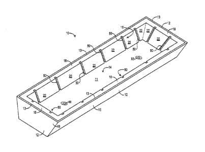
[0035] Referring to Figures 1A-1D, a tundish 10 comprises a shell
12 and
a refractory lining structure 18. The tundish 10 comprises a floor portion 14
and
sidewall portions 16. The refractory lining structure 18 comprises a first
layer 20, a
second layer 30 underlying at least a portion of the first layer 20, and a
third layer 40
underlying at least a portion of the second layer 30. The first layer 20
comprises a
refractory material (e.g., an aluminum oxide refractory material), the second
layer 30
comprises a refractory material (e.g., an aluminum oxide refractory material
or a
magnesium oxide refractory material), and the third layer 40 comprises a
refractory
-11 -
CA 03069751 2020-01-10
WO 2019/046042 PCT/US2018/047253
material suitable for use as a safety lining in a metallurgical vessel such as
the tundish
10. Examples of refractory materials suitable for use as a safety lining in a
metallurgical
vessel include, but are not limited to, fireclay, aluminum oxide refractory
materials,
magnesium oxide refractory materials, chrome refractory materials, or
zirconium oxide
refractory materials, or a combination of any thereof.
[0036] The third layer 40, which functions as a safety lining in
the tundish
10, can be applied in the tundish shell 12 as an assembly of refractory bricks
or panels,
optionally mortared, or as a monolithic refractory layer. In implementations
with a
monolithic refractory third layer 40, the refractory material can be applied,
for example,
by spraying, troweling, gunning, casting, or vibrating (e.g., dry-vibrating)
the third layer
40 in place using techniques known in the art. The first layer 20 and the
second layer
30 can comprise monolithic refractory layers that can be applied over the
third layer 40
by spraying, troweling, gunning, casting, or vibrating (e.g., dry-vibrating)
the second
layer 30 and the first layer 20 in place using techniques known in the art.
[0037] Still referring to Figures 1A-1D, the refractory lining
structure 18
further comprises elongated expansion joints 50 formed in the first surface 22
of the first
layer 20, and extending through the first surface 22 of the first layer 20 in
a substantially
vertical direction away from the floor surface 11 of the tundish 10 toward the
rim 13 of
the tundish 10. The floor surface 11 corresponds to the molten metal-
contacting
surface of a working lining 20' located on the floor 14 of the tundish 10. The
elongated
expansion joints 50 shown in Figures 1A-1D extend the entire height of the
first layer 20
on the sidewall 16 of the tundish 10. It is understood, however, that the
elongated
expansion joints 50 can extend less than the entire height of the first layer
20 (see, for
example, Figures 5A-6B, described below). Additionally, while two or more
elongated
expansion joints 50 are shown on each of the four intersecting sidewalls 16 of
the
tundish 10, it is understood that each sidewall of a metallurgical vessel can
comprise at
least one elongated expansion joint (see, for example, Figures 13, 14, 15A,
and 15B,
described below). Elongated expansion joints also can be located at the
intersections
of separate sidewalls in a metallurgical vessel (see, for example, Figure 13).
- 12 -
CA 03069751 2020-01-10
WO 2019/046042 PCT/US2018/047253
[0038] Referring to Figure 1C, during operation in a continuous
casting
process, the tundish 10 contains molten steel 60. The molten steel 60 is
introduced into
the tundish 10 from a ladle (not shown) through a ladle shroud 62 (arrows 64
indicate
the flow of the molten steel 60). The molten steel 60 flows out from the
tundish into
continuous casting molds (not shown) through openings 68 in ladle blocks 66.
The
molten steel 60 in the tundish 10 covers the elongated expansion joints 50
formed in the
first surface 22 of the first layer 20 up to just below a slag line 65 (slag
omitted for
clarity).
[0039] Figures 2A and 2B show a portion of the tundish 10
illustrated in
Figures 1A-1D. The first layer 20 of the refractory lining structure 18
comprises a first
surface 22 facing away from the sidewall 16 of the tundish 10, and a second
surface 24
located opposite the first surface and facing toward the sidewall 16 of the
tundish 10.
The second layer 30 comprises a first surface 32 facing away from the sidewall
16 of
the tundish 10, and a second surface 34 located opposite the first surface and
facing
toward the sidewall 16 of the tundish 10. The third layer 40 comprises a first
surface 42
facing away from the sidewall 16 of the tundish 10, and a second surface 44
located
opposite the first surface and facing toward the sidewall 16 of the tundish
10.
[0040] The first surface 22 of the first layer 20 is a molten metal-
contacting
layer in the tundish 10. The second surface 24 of the first layer 20 contacts
the first
surface 32 of the second layer 30. The second surface 34 of the second layer
30
contacts the first surface 42 of the third layer 40. The second surface 44 of
the third
layer 40 contacts the inwardly-facing surface of the tundish shell 12 along
the tundish
sidewall 16.
[0041] The elongated expansion joints 50 are formed in the first
surface 22
of the first layer 20 of the refractory lining structure 18 on the sidewall 16
of the tundish
10. The elongated expansion joints 50 extend through the entire thickness of
the first
layer 20 to a depth dimension (di). As shown in Figure 2B, the depth dimension
(di) of
the elongated expansion joints 50 is 100% of (i.e., coextensive with) the
thickness of the
first layer 20, and extends from the first surface 22 of the first layer 20 to
the second
- 13-
CA 03069751 2020-01-10
WO 2019/046042 PCT/US2018/047253
surface 24 of the first layer 20. The first surface 32 of the second layer 30
is therefore
partially exposed through the elongated expansion joints 50, as shown in
Figure 2A.
The depth dimension (di) of the elongated expansion joints 50 can be less than
100% of
the thickness of the first layer 20 (see, for example, Figures 4A and 4B,
described
below), and can range from 1-100%, 20-100%, 25-100%, 50-100% or 75-100% of the
thickness of the first layer 20. For example, the depth dimension (di) of the
elongated
expansion joints 50 can be, independently, at least 25%, at least 50%, or at
least 75%
of the thickness of the first layer 20. Although not shown, it is understood
that the depth
dimension (di) of the elongated expansion joints 50 can be greater than 100%
of the
thickness of the first layer 20. For example, the depth dimension (di) of the
elongated
expansion joints 50 can extend through the first surface 32 of the second
layer 30 and,
therefore, extend partially through the thickness of the second layer 30.
[0042] Still referring to Figures 2A and 2B, the elongated
expansion joints
50 extend in a substantially vertical direction away from the floor surface 11
of the
tundish 10 toward the rim 13 of the tundish 10. The elongated expansion joints
50
extend the entire height of the first layer 20 on the tundish sidewall 16 to a
vertical
height dimension (hi). The vertical height dimension (hi) of the elongated
expansion
joints 50 is therefore 100% of (i.e., coextensive with) the vertical height
dimension of the
first surface 22 of the first layer 20. The vertical height dimension (hi) of
the elongated
expansion joints 50 can be less than 100% of the vertical height dimension of
the first
surface 22 of the first layer 20 (see, for example, Figures 5A-6B, described
below). For
example, the vertical height dimension (hi) of the elongated expansion joints
50 can be,
independently, at least 25%, at least 50%, or at least 75% of the vertical
height
dimension (h1) of the first surface 22 of the first layer 20, or within a
range of 25-100%,
50-100%, or 75-100% of the vertical height dimension (h1) of the first surface
22 of the
first layer 20.
[0043] It is noted that the vertical height dimension of an
elongated
expansion joint is measured along the vertical axis (defined as an axis
perpendicular to
- 14 -
CA 03069751 2020-01-10
WO 2019/046042 PCT/US2018/047253
the horizontal plane). Therefore, the vertical height dimension of an
elongated
expansion joint can be different than the length of the elongated expansion
joint (which,
as described above, is used to calculate the aspect ratio of the elongated
expansion
joint). For example, an elongated expansion joint on a sidewall of a
metallurgical vessel
that is outwardly angled and therefore not perpendicular to the floor of the
metallurgical
vessel will have a length that is greater than its vertical height dimension.
Likewise, an
elongated expansion joint having a non-linear contour will have a length that
is greater
than its vertical height dimension.
[0044] As illustrated in Figure 2A, the elongated expansion joints
50 have
a horizontal width dimension (wi) substantially parallel to the first surface
22 of the first
layer 20. The horizontal width dimension (wi) can range from 1 millimeter
(0.04 inch) to
1830 millimeters (72 inches), or any sub-range subsumed therein, such as, for
example,
1-100 millimeters (0.04-4 inches), 5-50 millimeters (0.20-2.00 inches), 5-25
millimeters
(0.20-1.00 inches), or 5-13 millimeters (0.20-0.51 inch).
[0045] As described above, it was observed that during tundish pre-
heating, an overlying refractory working lining expands more than an
underlying
refractory back-up lining and/or safety lining, which can cause formation of
weak spots,
cracking, delamination, and spalling. More specifically, it was observed that
an
overlying refractory working lining can linearly expand at least 1`)/0 during
a pre-heating
operation. Accordingly, to effectively accommodate the thermal expansion, the
one or
more elongated expansion joints formed in the first layer (working lining) of
a refractory
lining structure, extending in a substantially vertical direction, should, at
least on some
implementations, have horizontal width dimensions that provide for 2.54 cm (1
inch) of
linear expansion for every 254 centimeters (100 inches) of the horizontal
dimension of
the first layer (working lining). In other words, the ratio of the sum of the
horizontal
width dimensions of the one or more elongated expansion joints formed in the
first layer
(working lining) of a refractory lining structure, to the total horizontal
dimension of the
first layer containing the elongated expansion joints, should be at least 0.01
(measured
at the intersection of the first surface of the first layer and the floor
surface of the tundish
- 15-
CA 03069751 2020-01-10
WO 2019/046042 PCT/US2018/047253
or other metallurgical vessel), and may be in the ranges 0.005-0.02, 0.01-
0.02, 0.005-
0.05, 0.01-0.05, or 0.005-0.10.
[0046] Referring again to Figures 1B, 1D, and 2A, the ratio of the
sum of
the horizontal width dimensions (wi) of the elongated expansion joints 50 (see
Figure
2A) to the total horizontal dimension (wi ) of the first surface 22 of the
first layer 20 (see
Figures 1B and 1D), on each of the four sidewalls 16 of the tundish 10, is at
least 0.005:
E1:1-1w.
"width ratio" > 0.005;
Wi
wherein the first surface 22 of the first layer 20 on each tundish sidewall 16
contains "n"
number of elongated expansion joints, each with a horizontal width (wi), and
each
extending substantially vertically; and wherein the total horizontal width
dimension (wi )
of the first surface 22 of the first layer 20 on each sidewall 16 is measured
at the
intersection of the first surface 22 with the floor surface 11. Accordingly,
for
metallurgical vessels comprising multiple interconnected sidewalls (tundish 10
having
four sidewalls 16¨ two sidewalls containing six elongated expansion joints,
and two
sidewalls containing two elongated expansion joints, see Figures 1A and 1D),
the width
ratio feature can hold for at least one of the multiple sidewalls, and in some
implementations, holds for all the constituent sidewalls.
[0047] The width ratio can be at least 0.005, 0.010, at least
0.015, at least
0.020, at least 0.025, or at least 0.030. For example, a width ratio of 0.017
provides
sufficient space for 2.54 centimeters (1 inch) of horizontal expansion per 152
centimeters (60 inches) of the horizontal dimension of the first surface of
the first layer,
and a width ratio of 0.025 provides sufficient space for 2.54 centimeters (1
inch) of
horizontal expansion per 102 centimeters (40 inches) of the horizontal
dimension of the
first surface of the first layer. The width ratio must be less than 1 (a width
ratio of 1
corresponds to an elongated expansion joint having a width that extends the
total
horizontal dimension (wi ) of the first surface of the first layer. The width
ratio can be
less than 1, less than 0.90, less than 0.75, less than 0.50, less than 0.25,
less than
- 16 -
CA 03069751 2020-01-10
WO 2019/046042 PCT/US2018/047253
0.15, less than 0.10, or less than 0.05. The width ratio can range from 0.005
to less
than 1, or any sub-range subsumed therein, such as, for example, 0.010-0.500
or
0.010-0.100.
[0048] As illustrated in Figure 2A, each elongated expansion joint
50 is
spaced apart from adjacent elongated expansion joints 50 by a horizontal
spacing (sj).
The horizontal spacing (sj) between each elongated expansion joint 50 can be
uniform
or vary independently. Each elongated expansion joint 50 can be spaced apart
from
adjacent elongated expansion joints 50 by a minimum horizontal spacing (sj) of
2.54
centimeters (1 inch). The number of elongated expansion joints 50, the
horizontal
spacing (sj) between each elongated expansion joint 50, and the horizontal
width
dimension (wi) of each elongated expansion joint 50, can be configured
together to
provide a width ratio of at least 0.010, as described above.
[0049] The elongated expansion joints can be formed in the first
surface of
the first layer (working lining) by cutting the joints into the first layer
after it is applied
over the second layer. For example, a saw, mill, or other suitable cutting
device can be
used to cut the elongated expansion joints into the first surface of the first
layer with a
given length, depth dimension, vertical height dimension, horizontal width
dimension,
contour, transverse shape, and orientation in the first layer.
[0050] Alternatively, the elongated expansion joints can be formed
in the
first surface of the first layer (working lining) using sacrificial or
otherwise removable
inserts or spacers. For example, referring to Figure 3, after the third layer
40
(functioning as a safety lining, for example) and the second layer 30
(functioning as a
deskulling separation layer, for example), a sacrificial or otherwise
removable
insert/spacer 55 can be positioned on the first surface 32 of the second layer
30. The
sacrificial/removable insert/spacer 55 has dimensions and a three-dimensional
shape
that corresponds, at least in part, to the dimensions and three-dimensional
shape of the
elongated expansion joints 50. The first layer 20 can then be applied onto the
first
surface 32 of the second layer 30 and around the sacrificial/removable
insert/spacer 55,
- 17-
CA 03069751 2020-01-10
WO 2019/046042 PCT/US2018/047253
for example, by spraying, troweling, gunning, casting, or vibrating (e.g., dry-
vibrating)
the first layer 20 in place.
[0051] The insert/spacer 55 can be made of a sacrificial material,
such as,
for example, wood, plastic, cardboard, plywood, particle board, oriented
strand board, or
other decomposable material, which decomposes during a dry-out operation when
the
applied layers are heated to relatively high temperatures (e.g., at least 700
F (371 C)).
During the dry-out operation, the sacrificial insert/spacer 55 can pyrolyze or
otherwise
volatilize (i.e., burn-out), leaving a negative impression in the first layer
20, and thereby
forming an elongated expansion joint 50.
[0052] The insert/spacer 55 can be made of a non-sacrificial
material,
such as, for example, metal, which does not decompose during a dry-out
operation,
provided the material of the first layer (e.g., an aluminum oxide refractory
material) does
not strongly adhere to the non-sacrificial material so that the insert/spacer
55 can be
physically removed from the first layer 20, leaving a negative impression in
the first layer
20, and thereby forming an elongated expansion joint 50. The removable
insert/spacer
55 can be removed after application of the material forming the first layer
20, and before
a subsequent dry-out operation, provided the "wet" layer has sufficient
cohesion and
structural integrity to maintain the negative impression formed by the
insert/spacer 55
during a dry-out operation; otherwise, the insert/spacer 55 can be removed
after
completion of a dry-out operation or after at least a portion of a dry-out
operation.
[0053] As described above, the depth dimension of the elongated
expansion joints 50 can be less than 100% of the thickness of the first layer
20. As
shown in Figures 4A and 4B, the elongated expansion joints 50 extend the
entire height
of the first surface 22 of the first layer 20 on the tundish sidewall 16, but
only extend
through a portion of the thickness of the first layer 20. Referring to Figure
4B, the depth
dimension (d) of the elongated expansion joints 50 extends from the first
surface 22 of
the first layer 20 to a recessed surface 23 of the first layer 20. The first
surface 32 of
the second layer 30 remains covered by the portion of the thickness of the
first layer 20
between the recessed surface 23 and the second surface 24 of the first layer
20. The
- 18-
CA 03069751 2020-01-10
WO 2019/046042 PCT/US2018/047253
depth dimension (d) of the elongated expansion joints 50 can range from 1 to
less than
100% of the thickness of the first layer 20, and can range from 1-100%, 20-
100%, 25-
100%, 50-100% or 75-100% of the thickness of the first layer 20. For example,
the
depth dimension (d) of the elongated expansion joints 50 can be,
independently, at least
25%, at least 50%, or at least 75% of the thickness of the first layer 20.
[0054] As
described above, the vertical height dimension of the elongated
expansion joints 50 can be less than 100% of the vertical height dimension of
the first
surface 22 of the first layer 20. As shown in Figures 5A and 5B, the elongated
expansion joints 50 extend through the entire thickness of the first layer 20
(although it
is understood that the elongated expansion joints 50 can extend through a
portion of the
thickness of the first layer 20 as illustrated above in connection with
Figures 4A and 4B),
but only extend a portion of the height of the first surface 22 of the first
layer 20 on the
tundish sidewall 16. The elongated expansion joints 50 have a vertical height
dimension (hi) and the first surface 22 of the first layer 20 on the tundish
sidewall 16 has
a vertical height dimension (hi), wherein h; < hi. The vertical height
dimension (hi) of
the elongated expansion joints 50 can be, independently, at least 25%, at
least 50%, or
at least 75% of the vertical height dimension of the first surface 22 of the
first layer 20
hi/hi 0.25, hi/hi 0.50, or hj/hi 0.75), or within a range of 25-100%, 50-100%,
or 75-100% of the vertical height dimension (h1) of the first surface 22 of
the first layer
20. The elongated expansion joints 50 extend in a substantially vertical
direction away
from the floor surface 11 of the tundish 10, toward the rim 13 of the tundish
10, but the
elongated expansion joints 50 extend from a point above the floor surface 11
to a point
below the rim 13.
[0055]
Figures 6A and 6B illustrate another example of a refractory lining
structure 18 comprising elongated expansion joints 50 having vertical height
dimensions
(hi) that are less than 100% of the vertical height dimension of the first
surface 22 of the
first layer 20 (hi) ¨ i.e., h; < hi. As shown in Figures 6A and 6B, the
elongated
expansion joints 50 extend through the entire thickness of the first layer 20
(although it
is understood that the elongated expansion joints 50 can extend through a
portion of the
- 19-
CA 03069751 2020-01-10
WO 2019/046042 PCT/US2018/047253
thickness of the first layer 20 as illustrated above in connection with
Figures 4A and 4B),
but only extend along the portion of the height of the first surface 22 of the
first layer 20
on the tundish sidewall 16 located between the floor surface 11 and a slag
line 65 (see
Figure 1C, described above).
[0056] Figures 7A and 7B illustrate an example of a refractory
lining
structure 18 comprising elongated expansion joints 50 comprising portions 51
that
extend below the floor surface 11, which corresponds to the molten metal-
contacting
surface of a working lining 20' located on the floor 14 of a tundish. The sub-
floor portion
51 of the expansion joint 50 can be formed, for example, when using a
sacrificial/removable insert/spacer (see the insert/spacer 55 in Figure 3),
and the
material forming the first layer 20 and the floor working lining 20' are
applied around the
sacrificial/removable insert/spacer, for example, by spraying, troweling,
gunning,
casting, or vibrating (e.g., dry-vibrating) the first layer 20 and the floor
working lining 20'
in place.
[0057] In addition to the at least one elongated expansion joint
extending
in a substantially vertical direction, the refractory lining structure can
further comprise at
least one elongated expansion joint formed in the first surface of the first
layer and
extending in a horizontal direction. A horizontally extending, elongated
expansion joint
70 is shown in Figure 8 intersecting the substantially vertically extending,
elongated
expansion joints 50. The horizontally extending, elongated expansion joint 70
can
extend the entire horizontal length of the first surface 22 of the first layer
20, or a portion
of the horizontal length of the first surface 22 of the first layer 20.
Although one
horizontally extending, elongated expansion joint 70 is shown in Figure 8, it
is
understood that two or more horizontally extending, elongated expansion joints
may be
formed in the first surface of the first layer in a refractory lining
structure in accordance
with this specification. Additionally, while the horizontally extending,
elongated
expansion joint 70 is shown in Figure 8 oriented parallel to a horizontal
axis, it is
understood that a refractory lining structure in accordance with this
specification can
comprise a substantially horizontally extending, elongated expansion joint in
which the
- 20 -
CA 03069751 2020-01-10
WO 2019/046042 PCT/US2018/047253
joint is angled up to 45 relative to a horizontal axis. A refractory lining
structure in
accordance with this specification also can comprise a substantially
horizontally
extending, elongated expansion joint having a non-linear contour such as, for
example,
a polyline contour or a curved contour (e.g., having an arc shape, sine wave
shape, or
spline shape).
[0058] The elongated expansion joints described above are
illustrated
having a substantially vertical linear contour (i.e., a vertical line
contour). However, a
refractory lining structure in accordance with this specification can comprise
a
substantially vertically extending, elongated expansion joint having other
contours
and/or orientations. For example, as illustrated in Figure 9, an elongated
expansion
joint 50 can have a substantially vertical linear contour oriented diagonally
across the
first surface 22 of the first layer 20 (i.e., a diagonal line contour). The
elongated
expansion joint 50 can form a diagonal angle 0 ranging from greater than zero
to 45
relative to a substantially vertical axis 57 in the plane of the first surface
22 of the first
layer 20.
[0059] A refractory lining structure in accordance with this
specification
also can comprise a substantially vertically extending, elongated expansion
joint having
a non-linear contour such as, for example, a polyline contour (see Figure 10)
or a
curved contour (e.g., having an arc shape, as shown in Figure 11), sine wave
shape, or
spline shape). Figure 12 shows a substantially vertically extending, elongated
expansion joint 50 having a contour combining a diagonal line and a curve.
Thus, a
refractory lining structure in accordance with this specification can comprise
an
elongated contour selected from the group consisting of a vertical line, a
diagonal line, a
polyline, and a curve, and a combination of any thereof.
[0060] The invention described in this specification includes a
metallurgical
vessel comprising a refractory lining structure, as described above. A
metallurgical
vessel can comprise a floor and a sidewall extending from the floor in a
substantially
vertical direction. The refractory lining structure, as described above, can
be located on
at least a portion of the sidewall of the metallurgical vessel. The
metallurgical vessel
- 21 -
CA 03069751 2020-01-10
WO 2019/046042 PCT/US2018/047253
can comprise a tundish configured for use in a continuous casting operation,
wherein
the tundish comprises at least four intersecting sidewalls. The refractory
lining
structure, as described above, can be located on at least a portion of at
least one of the
four sidewalls. Although the tundish 10 described above comprises four
sidewalls in a
rectangular plan orientation, it is understood that the refractory lining
structure can be
used with different tundish designs.
[0061] For example, as shown in Figure 13, the refractory lining
structure,
as described above, can be used in a T-shaped tundish 110 having eight
sidewalls 116.
The refractory lining structure 118 can be located on the outer shell 112 of
the tundish
110 at the sidewalls 116. Substantially vertically extending, elongated
expansion joints
150 are formed in the first surfaces 122 of the first layers, and are also
formed at the
intersections of the eight sidewalls 116. Although not shown, the refractory
lining
structure 118 can be omitted from some of the sidewalls 116, for example, the
sidewalls
116 adjacent to an impact pad 176, and/or the elongated expansion joints can
be
omitted from some or all of the intersections of the eight sidewalls.
[0062] Figure 14 shows a delta-type tundish 210 having six
sidewalls 216.
A refractory lining structure 218 can be located on the outer shell 212 of the
tundish 210
at the sidewalls 216. Substantially vertically extending, elongated expansion
joints 250
are formed in the first surfaces 222 of the first layers (and also optionally
can be formed
at the intersections of one or more of the six sidewalls 216, not shown).
Although not
shown, the refractory lining structure 218 can be omitted from some of the
sidewalls
216, for example, the sidewalls 216 adjacent to an impact pad 276.
[0063] The elongated expansion joints shown in the drawings
described
above are illustrated as uniform in orientation in each metallurgical vessel,
and having
uniform dimensions, and shape (i.e., elongated contour and transverse (cross-
sectional)
shape). It is understood, however, that in any given metallurgical vessel
comprising the
refractory lining structure described above, the shape, dimensions,
orientation, number,
and spacing of the elongated expansion joints can vary from joint-to-joint.
For example,
referring to Figures 15A and 15B, a tundish 310 comprises a shell 312 and a
refractory
- 22 -
CA 03069751 2020-01-10
WO 2019/046042 PCT/US2018/047253
lining structure 318. The tundish 310 comprises a floor portion 314 and
sidewall
portions 316. The refractory lining structure 318 comprises a first layer 320,
a second
layer 330 underlying at least a portion of the first layer 320, and a third
layer 340
underlying at least a portion of the second layer 330. The first layer 320,
second layer
330, and third layer 340 each independently comprise a refractory material, as
described above. It is also noted that the second layer 330 can be omitted and
the first
layer 320 positioned directly on the third layer 340, in which case the
refractory lining
structure 318 comprises a two-layer structure comprising only first and second
layers.
[0064] Still referring to Figures 15A and 15B, the refractory
lining structure
318 further comprises elongated expansion joints 350 and 350' formed in the
first
surface 322 of the first layer 320, and extending through the first surface
322 of the first
layer 320 in a substantially vertical direction away from the floor surface
311 of the
tundish 310 toward the rim 313 of the tundish 310. The floor surface 311
corresponds
to the molten metal-contacting surface of a working lining 320' located on the
floor 314
of the tundish 310. The elongated expansion joints 350 and 350' extend the
entire
height of the first layer 320 on the sidewall 316 of the tundish 310. It is
understood,
however, that the elongated expansion joints 350 and 350' can extend less than
the
entire height of the first layer 320, as described above. The elongated
expansion joints
350' located on the long sidewalls of the tundish 310 have greater horizontal
widths
than the elongated expansion joints 350 located on the short sidewalls of the
tundish
310.
[0065] The depth and width dimensions, and the cross-sectional
shape, of
any given elongated expansion joint can vary from point-to-point along the
length of the
elongated expansion joint. Additionally, the thicknesses of the constituent
layers of the
refractory lining structure can vary from location-to-location within a given
metallurgical
vessel. For example, the first layer (working lining) can be thinner above the
slag line
than below the slag line in a tundish comprising the refractory lining
structure.
Alternatively or in addition, the first layer can comprise a region localized
around the
slag line that is thicker than the portions of the first layer above and below
the slag line.
- 23 -
CA 03069751 2020-01-10
WO 2019/046042 PCT/US2018/047253
Likewise, in some implementations, the second layer and/or the first layer
(working
lining) can be omitted from portions of the sidewalls of a tundish (e.g.,
above the slag
line).
[0066] Although the refractory lining structure is described above
in
tundishes for use in steel continuous casting processes, it is understood that
the
refractory lining structure can be used in other metallurgical vessels for
both ferrous and
nonferrous applications, such as, for example, ladles. Likewise, while the
refractory
lining structure is described above in connection with drawings illustrating
two-strand
tundishes, it is understood that the refractory lining structure can be used
in single-
strand tundishes or multiple-strand tundishes having two or more well blocks
per
tundish (e.g., six-strand tundishes). Additionally, for ease of illustration,
the tundishes
shown in the drawings described above omit tundish furniture and other tundish
components (e.g., dams, weirs, baffles, overflow spouts, stopper rods, slide
gates, and
the like). It is understood, however, that tundishes comprising the refractory
lining
structure described above can also comprise tundish furniture, other tundish
components, and have non-planar and/or discontinuous floor surfaces.
EXAMPLES
Example 1:
[0067] A tundish configured for the continuous casting of steel, and
having
a pre-installed refractory safety lining (third layer), was sprayed with
BASILITE 302 (a
magnesite-olivine refractory spray coating, having a minimum MgO content of
50%,
available from Vesuvius USA Corporation). The BASILITE 302 layer was sprayed
1-
to-1.5 inches thick on the floor and sidewalls of the tundish (about 2-inches
thick on the
slag line), thereby forming a 1-to-2-inches-thick second layer.
[0068] The applied BASILITE 302 layer was dried out by first
heating the
layer at 600 F for 0.5 hours, and then heating the layer at 1000 F for 3
hours. The
- 24 -
CA 03069751 2020-01-10
WO 2019/046042 PCT/US2018/047253
tundish was cooled to below 110 F, and a high alumina working lining was
gunned over
the BASILITE 302 layer, thereby forming a first layer. Before the high
alumina working
lining was gunned over the BASILITE 302 layer, sacrificial inserts/spacers
made of
plywood panels (60-inches x 1.75-inches x 0.375-inches) were positioned on the
BASILITE 302 layer on one of the four tundish sidewalls in a substantially
vertical
orientation every 15 inches along the horizontal width of the BASILITE 302
layer. The
plywood inserts/spacers were positioned with a 60-inches x 0.375-inch face in
contact
with the BASILITE 302 layer, and the 60-inches x 1.75-inches faces were
oriented
substantially perpendicular to the surface of the BASILITE 302 layer.
Additionally,
before the high alumina working lining was gunned, the BASILITE 302 layer was
sprayed with water to moisten the surface of the BASILITE 302 layer.
[0069] After the high alumina working lining was gunned over the
BASILITE 302 layer and the plywood inserts/spacers, any residual refractory
material
was cleaned from the exposed surfaces of the plywood inserts/spacers (i.e.,
the
surfaces that were not embedded in the applied layer of high alumina working
lining) to
ensure that the plywood inserts/spacers burned-out during the drying of the
high
alumina working lining. Additionally, on the three tundish sidewalls without
plywood
inserts/spacers, elongated expansion joints having a 0.25 inch (0.64 cm)
horizontal
width were cut into the applied layer of high alumina working lining using a
saw at every
15 inches (38 cm) along the horizontal width of the layer. The cut elongated
expansion
joints were oriented substantially vertically through the surface of the
applied first layer.
The applied layer of high alumina working lining was dried out by heating the
layer in
the following sequence: 1 hour at 350 F (180 C) 1
hour at 500 F (260 C) 1 hour
at 700 F (370 C) 2 hours at 950 F (510 C). Thermocouples positioned between
the
first layer and the second layer indicated that the interface temperature
gradually
increased to a peak temperature of 700 F (370 C) during the dry-out sequence.
[0070] The plywood inserts/spacers were completely burned out
during the
dry-out sequence, forming 0.375-inch (0.95 cm) wide elongated expansion joints
that
extended substantially vertically through the surface of the first layer. The
previously
- 25 -
CA 03069751 2020-01-10
WO 2019/046042 PCT/US2018/047253
cut 0.25-inch (0.64 cm) wide elongated expansion joints were re-cut to a 0.375-
inch
(0.95 cm) width. The elongated expansion joints formed by the burned-out
plywood
inserts/spacers were also re-cut with a 0.375-inch (0.95 cm) wide saw to
ensure that the
depth of all the elongated expansion joints extended through the entire
thickness of the
first layer. A 0.375-inch (0.95 cm) wide horizontal expansion joint was also
cut around
the perimeter of the tundish through the surface of the first layer on all
four of the
tundish sidewalls at approximately mid-height on the sidewalls.
[0071] The tundish was subjected to a 2000 F (1100 C) preheating
operation for approximately 14 hours, after which the first layer exhibited
minimal
observable cracking and no observable delamination or spalling. The pre-heated
tundish was used in a steel continuous casting campaign, after which the
tundish was
cooled and the residual steel in the tundish solidified to form a skull. The
entire first
layer remained adhered to the tundish sidewall during the continuous casting
campaign.
The cooled tundish was inverted and the skull fell out under the influence of
gravity.
The third layer (safety lining) was not damaged, which indicated that the
elongated
expansion joints did not compromise the shielding and insulating effectiveness
of the
first and second layers.
ASPECTS OF THE INVENTION
[0072] Various aspects of the invention include, but are not
limited to, the
following numbered clauses.
1. A refractory lining structure for a metallurgical vessel comprising:
a first layer having a first surface facing away from a sidewall of a
metallurgical
vessel and a second surface located opposite the first surface and facing
toward the
sidewall of the metallurgical vessel, the first layer comprising a first
refractory material;
a second layer underlying at least a portion of the first layer, the second
layer
having a first surface facing away from the sidewall of the metallurgical
vessel and a
second surface located opposite the first surface and facing toward the
sidewall of the
- 26 -
CA 03069751 2020-01-10
WO 2019/046042 PCT/US2018/047253
metallurgical vessel, the second layer comprising a second refractory
material, wherein
the second surface of the first layer contacts the first surface of the second
layer; and
at least one elongated expansion joint formed in the first surface of the
first layer
and extending through the first surface of the first layer in a substantially
vertical
direction.
2. The refractory lining structure of clause 1, wherein the first
refractory material and
the second refractory material are independently selected from the group
consisting of
aluminum oxide refractory materials, magnesium oxide refractory materials,
chrome
refractory materials, and zirconium oxide refractory materials, and
combinations of any
thereof.
3. The refractory lining structure of clause 1 or clause 2, wherein the
first refractory
material comprises an aluminum oxide refractory material, and wherein the
second
refractory material comprises an aluminum oxide refractory material, a
magnesium
oxide refractory material, a chrome refractory material, a zirconium oxide
refractory
materials, or a combination of any thereof.
4. The refractory lining structure of any one of clauses 1-3, wherein the
first refractory
material comprises an aluminum oxide refractory material, and wherein the
second
refractory material comprises a magnesium oxide refractory material.
5. The refractory lining structure of any one of clauses 1-3, wherein the
first refractory
material and the second refractory material both comprise an aluminum oxide
refractory
material.
6. The refractory lining of any one of clauses 1-3, wherein the first
refractory material
comprises an aluminum oxide refractory material, and wherein the second
refractory
material comprises an olivine/dunite refractory material.
- 27 -
CA 03069751 2020-01-10
WO 2019/046042 PCT/US2018/047253
7. The refractory lining on any one of clauses 1-3, wherein the first
refractory material
comprises an aluminum oxide refractory material, and wherein the second
refractory
material comprises a dolomite refractory material.
8. The refractory lining structure of any one of clauses 1-7, wherein the
at least one
elongated expansion joint comprises an elongated contour selected from the
group
consisting of vertical lines, diagonal lines, polylines, and curves, and
combinations of
any thereof.
9. The refractory lining structure of any one of clauses 1-8, wherein the
at least one
elongated expansion joint has an aspect ratio of greater than 0.05.
10. The refractory lining structure of any one of clauses 1-9, wherein the at
least one
elongated expansion joint has an aspect ratio of at least 0.1.
11. The refractory lining structure of any one of clauses 1-10, wherein the at
least one
elongated expansion joint has an aspect ratio of at least 50.
12. The refractory lining structure of any one of clauses 1-11, wherein the at
least one
elongated expansion joint has an aspect ratio of at least 75.
13. The refractory lining structure of any one of clauses 1-12, wherein the at
least one
elongated expansion joint has an aspect ratio of at least 100.
14. The refractory lining structure of any one of clauses 1-13, wherein the at
least one
elongated expansion joint is characterized by a width ratio of at least 0.005.
15. The refractory lining structure of any one of clauses 1-14, wherein the at
least one
elongated expansion joint is characterized by a width ratio of at least 0.010.
16. The refractory lining structure of any one of clauses 1-15, wherein the at
least one
elongated expansion joint is characterized by a width ratio of at least 0.015.
- 28 -
CA 03069751 2020-01-10
WO 2019/046042 PCT/US2018/047253
17. The refractory lining structure of any one of clauses 1-16, wherein the at
least one
elongated expansion joint is characterized by a width ratio of at least 0.025.
18. The refractory lining structure of any one of clauses 1-17, wherein the
width
dimension of the at least one elongated expansion joint ranges from 1
millimeter (0.04
inch) to 100 millimeters (4 inches).
19. The refractory lining structure of any one of clauses 1-18, wherein the
width
dimension of the at least one elongated expansion joint ranges from 5
millimeters (0.20
inch) to 25 millimeters (1 inch).
20. The refractory lining structure of any one of clauses 1-19, wherein the at
least one
elongated expansion joint has a depth dimension extending from the first
surface of the
first layer toward the second surface of the first layer, and wherein the
depth dimension
is at least 50% of the thickness of the first layer.
21. The refractory lining structure of any one of clauses 1-20, wherein the
depth
dimension of the at least one elongated expansion joint is 100% of the
thickness of the
first layer, wherein the depth dimension of the at least one elongated
expansion joint
extends from the first surface of the first layer to the second surface of the
first layer,
and wherein the first surface of the second layer is partially exposed by the
at least one
elongated expansion joint.
22. The refractory lining structure of any one of clauses 1-21, wherein the
thickness of
the first layer and the thickness of the second layer, independently, range
from 1
millimeter (0.04 inch) to 65 millimeters (2.6 inches).
23. The refractory lining structure of any one of clauses 1-22, wherein the
thickness of
the first layer and the thickness of the second layer, independently, range
from 25
millimeters (1 inch) to 50 millimeters (2 inches).
- 29 -
CA 03069751 2020-01-10
WO 2019/046042 PCT/US2018/047253
24. The refractory lining structure of any one of clauses 1-23, wherein the at
least one
elongated expansion joint has a vertical height dimension that is at least 75%
of the
vertical height dimension of the first surface of the first layer.
25. The refractory lining structure of any one of clauses 1-24, wherein the at
least one
elongated expansion joint has a vertical height dimension that is at least
100% of the
vertical height dimension of the first surface of the first layer.
26. The refractory lining structure of any one of clauses 1-25, comprising a
plurality of
elongated expansion joints formed in the first surface of the first layer,
wherein each of
the plurality of elongated expansion joints extends through the first surface
of the first
layer in a substantially vertical direction, and wherein the plurality of
elongated
expansion joints are spaced apart from each other in a horizontal direction by
a
minimum of 2.54 centimeters (1 inch).
27. The refractory lining structure of any one of clauses 1-26, further
comprising an
elongated expansion joint formed in the first surface of the first layer and
extending
through the first surface of the first layer in a substantially horizontal
direction.
28. The refractory lining structure of any one of clauses 1-27, further
comprising a third
layer underlying at least a portion of the second layer, the third layer
having a first
surface facing away from the sidewall of the metallurgical vessel and a second
surface
located opposite the first surface and facing toward and contacting the
sidewall of the
metallurgical vessel, the third layer comprising a third refractory material,
wherein the
second surface of the second layer contacts the first surface of the third
layer.
29. A metallurgical vessel comprising:
a floor and a sidewall extending from the floor in a substantially vertical
direction;
and
- 30 -
CA 03069751 2020-01-10
WO 2019/046042 PCT/US2018/047253
the refractory lining structure of any one of clauses 1-28 located on at least
a
portion of the sidewall of the metallurgical vessel.
30. The metallurgical vessel of clause 29, wherein the metallurgical vessel
comprises
a tundish configured for use in a continuous casting operation, wherein the
tundish
comprises at least four intersecting sidewalls, wherein the refractory lining
structure is
located on at least a portion of the at least four sidewalls, and wherein at
least one
elongated expansion joint is formed in the first surface of the first layer on
each of the at
least four sidewalls, and wherein the elongated expansion joints extend
through the first
surfaces of the first layers in a substantially vertical direction.
31. A method of producing a refractory lining structure of any of clauses 1-28
in a
refractory vessel, comprising
a) Providing a metallurgical vessel having lateral and bottom walls having a
refractory safety lining;
b) Applying a second refractory layer comprising a second refractory material
over
the refractory safety lining;
c) Applying a first refractory layer comprising a first refractory material
over the
second refractory layer, wherein the first refractory layer has a first
surface
facing away from a sidewall of the metallurgical vessel; and
d) Forming at least one elongated expansion joint in the first surface of the
first
layer and extending through the first surface of the first layer in a
substantially
vertical direction.
32. The method of clause 32, wherein the first refractory material comprises
at least
50% alumina by mass.
** **
[0073] Various features and characteristics are described in this
specification and illustrated in the drawings to provide an overall
understanding of the
- 31 -
CA 03069751 2020-01-10
WO 2019/046042 PCT/US2018/047253
invention. It is understood that the various features and characteristics
described in this
specification and illustrated in the drawings can be combined in any operable
manner
regardless of whether such features and characteristics are expressly
described or
illustrated in combination in this specification. The Inventors and the
Applicant
expressly intend such combinations of features and characteristics to be
included within
the scope of this specification, and further intend the claiming of such
combinations of
features and characteristics to not add new subject matter to the application.
As such,
the claims can be amended to recite, in any combination, any features and
characteristics expressly or inherently described in, or otherwise expressly
or inherently
supported by, this specification. Furthermore, the Applicant reserves the
right to amend
the claims to affirmatively disclaim features and characteristics that may be
present in
the prior art, even if those features and characteristics are not expressly
described in
this specification. Therefore, any such amendments will not add new subject
matter to
the specification or claims, and will comply with written description,
sufficiency of
description, and added matter requirements (e.g., 35 U.S.C. 112(a) and
Article 123(2)
EPC). The invention can comprise, consist of, or consist essentially of the
various
features and characteristics described in this specification.
[0074] Also, any numerical range recited in this specification
includes the
recited endpoints and describes all sub-ranges of the same numerical precision
(i.e.,
having the same number of specified digits) subsumed within the recited range.
For
example, a recited range of "1.0 to 10.0" describes all sub-ranges between
(and
including) the recited minimum value of 1.0 and the recited maximum value of
10.0,
such as, for example, "2.4 to 7.6," even if the range of "2.4 to 7.6" is not
expressly
recited in the text of the specification. Accordingly, the Applicant reserves
the right to
amend this specification, including the claims, to expressly recite any sub-
range of the
same numerical precision subsumed within the ranges expressly recited in this
specification. All such ranges are inherently described in this specification
such that
amending to expressly recite any such sub-ranges will comply with written
description,
sufficiency of description, and added matter requirements (e.g., 35 U.S.C.
112(a) and
Article 123(2) EPC).
- 32 -
CA 03069751 2020-01-10
WO 2019/046042 PCT/US2018/047253
[0075] The grammatical articles "one", "a", "an", and "the", as
used in this
specification, are intended to include at least one" or one or more", unless
otherwise
indicated or required by context. Thus, the articles are used in this
specification to refer
to one or more than one (i.e., to at least one") of the grammatical objects of
the article.
By way of example, "a component" means one or more components, and thus,
possibly,
more than one component is contemplated and can be employed or used in an
implementation of the invention. Further, the use of a singular noun includes
the plural,
and the use of a plural noun includes the singular, unless the context of the
usage
requires otherwise.
[0076] Table of Elements
10. Tundish
11. Tundish floor surface
12. Tundish shell
13. Tundish rim
14. Tundish floor
16. Sidewall portions of tundish
18. Refractory lining structure
20. First layer of refractory lining structure
20'. Metal-contacting surface of a working lining
22. First surface of the first layer
23. Recessed surface of the first layer
24. Second surface of the first layer
30. Second layer of refractory lining structure
32. First surface of the second layer
34. Second surface of the second layer
40. Third layer of refractory lining structure
42. First surface of the third layer
44. Second surface of the third layer
50. Elongated expansion joint
- 33 -
CA 03069751 2020-01-10
WO 2019/046042
PCT/US2018/047253
51. Portions of expansion joints extending below the floor surface
55. Insert/spacer
57. Substantially vertical axis in the plane of the first surface of the
first layer
60. Molten steel
62. Ladle shroud
64. Indication of flow of molten steel
65. Slag line
66. Ladle blocks
68. Openings in ladle blocks
70. Horizontally extended, elongated expansion joint
110. T-shaped tundish
112. Outer shell of tundish
116. Sidewalls
118. Refractory lining structure
122. First surfaces of the first layers
150. Vertically extending, elongated expansion joints
176. Impact pad
210. Delta-type tundish
212. Outer shell of tundish
216. Sidewalls
218. Refractory lining structure
222. First surfaces of the first layer
250. Substantially vertically extending, elongated expansion joints
276. Impact pad
310. Tundish
311. Floor surface of the tundish
- 34 -