Note: Descriptions are shown in the official language in which they were submitted.
CA 03069881 2020-01-14
WO 2019/020729 PCT/EP2018/070249
1
ANNULAR BARRIER FOR SMALL DIAMETER WELLS
Description
The present invention relates to an annular barrier for being mounted as part
of a
well tubular metal structure for providing zonal isolation in a small diameter
borehole downhole for isolating a first zone from a second zone. The present
invention also relates to a well tubular metal structure having a plurality of
tubular sections and at least one annular barrier according to the present
invention, and to a completion method of preparing an annular barrier
according
to the present invention.
Annular barriers for providing a zone isolation, e.g. for isolating a
hydrocarbon-
containing zone from a water producing zone, is provided by arranging an
isolating element, such as an expandable metal sleeve surrounding the base
pipe, such as the casing or liner, and are expanded by liquid from within the
base
pipe. However, in small diameter wells there is no room between the inner wall
of
the borehole and the base pipe for such annular barrier solutions, because the
inner diameter of the base pipe would be too small for an efficient
production. In
such small diameter wells other solutions, such as swellable material around
the
base pipe, are used to provide the annular barrier.
The swelling of the swellable material is dependent on fluid content and
temperature in the well and, most importantly, the deployment time from
entering the well and until arrival at the determined position. Sometimes
during
deployment, the casing or well tubular metal structure gets stuck or is just
much
more difficult to deploy, resulting in the deployment time being much longer
than
planned, and in these cases, the swelling may occur too early and the barrier
is
then set too early. In small diameter wells, the space between the base pipe
and
the borehole wall is very narrow in order to maximise the inner diameter of
the
base and thus the production volume. Thus, in such small diameter wells, the
risk
of the casing or well tubular metal structure getting stuck is even higher
than in
larger wells.
Thus, it is an object of the present invention to wholly or partly overcome
the
above disadvantages and drawbacks of the prior art. More specifically, it is
an
CA 03069881 2020-01-14
WO 2019/020729 PCT/EP2018/070249
2
object to provide an improved annular barrier for small diameter wells which
does not set too early, i.e. before the barrier is in the intended position in
the
borehole.
The above objects, together with numerous other objects, advantages and
features, which will become evident from the below description, are
accomplished
by a solution in accordance with the present invention by an annular barrier
for
being mounted as part of a well tubular metal structure for providing zonal
isolation in a small diameter borehole downhole for isolating a first zone
from a
second zone, comprising:
- an expandable metal sleeve having a first end and a second end and an
outer face facing the borehole,
- a first end part having a first end connected to the first end of the
expandable metal sleeve and a second end for being mounted as part of
the well tubular structure, and
- a second end part having a first end connected to the second end of
the expandable metal sleeve and a second end for being mounted as
part of the well tubular structure,
wherein the first end of the first end part is connected end to end to the
first end
of the expandable metal sleeve, and the first end of the second end part is
connected end to end to the second end of the expandable metal sleeve, and
wherein the second ends of the end parts are provided with male or female
thread connections for being mounted to corresponding male or female thread
connections of the well tubular metal structure.
The above objects, together with numerous other objects, advantages and
features, which will become evident from the below description, are
accomplished
by a solution in accordance with the present invention by an annular barrier
for
being mounted as part of a well tubular metal structure for providing zonal
isolation in a small diameter borehole downhole for isolating a first zone
from a
second zone, the annular barrier having an inner face and comprising:
- an expandable metal sleeve having a first end and a second end, an
inner face and an outer face facing the borehole,
- a first end part having a first end connected to the first end of the
expandable metal sleeve and a second end for being mounted as part of
the well tubular structure, the first end part having an inner face and
CA 03069881 2020-01-14
WO 2019/020729 PCT/EP2018/070249
3
- a second end part having a first end connected to the second end of
the expandable metal sleeve and a second end for being mounted as
part of the well tubular structure, the second end part having an inner
face,
wherein the first end of the first end part is connected end to end to the
first end
of the expandable metal sleeve, and the first end of the second end part is
connected end to end to the second end of the expandable metal sleeve, the
expandable metal sleeve and the first and second end parts are connected so
that the inner face of the expandable metal sleeve and the inner faces of the
first
and second end parts constitute the inner face of the annular barrier, and
wherein the second ends of the end parts are provided with male or female
thread connections for being mounted to corresponding male or female thread
connections of the well tubular metal structure.
By the first end of the first end part being connected "end to end" to the
first end
of the expandable metal sleeve, and the first end of the second end part being
connected "end to end" to the second end of the expandable metal sleeve, is
meant that the ends are abutting and welded together or connected by a
threading or similar connection. The inner face of the expandable metal sleeve
thereby forms part of the inner face of the annular barrier and when mounted
to
the well tubular metal structure forms part of the inner face of the well
tubular
metal structure. Thus, the expandable metal sleeve does not overlap a tubular
section of the well tubular metal structure nor the end parts in its entire
thickness
or length.
By having end parts having internal or external threads, the annular barrier
can
be connected as part of any well tubular metal structure, and the well tubular
metal structure can be made with a substantially smaller outer diameter and
fit
into small diameter wells than annular barriers with a base pipe and a
surrounding sleeve. The expandable metal sleeve is tested for expansion up to
a
certain radial expansion and by having the interchangeable end parts; the
tested
and qualified expandable metal sleeve can fit a variety of different well
tubular
metal structure and can quickly be changed on the platform or rig with other
end
parts to fit the borehole.
CA 03069881 2020-01-14
WO 2019/020729 PCT/EP2018/070249
4
Furthermore, the first end part, the second end part and the expandable metal
sleeve may form one tubular section configured to be mounted as part of the
well
tubular metal structure.
Moreover, the first and second end parts and the expandable metal sleeve are
mounted in succession with each other.
In addition, the annular barrier may be without any enclosed space.
Also, the expandable metal sleeve and the first and second end parts are
connected so that the inner face of the expandable metal sleeve and the inner
faces of the first and second end parts constitute the inner face of the
annular
barrier configured to be in contact with a production fluid conveyed by the
well
tubular metal structure.
Furthermore, the expandable metal sleeve may be arranged in a non-overlapping
configuration with other sections of the annular barrier.
Also, the expandable metal sleeve may be arranged in a non-overlapping
configuration with the end parts in an entire thickness and/or length of the
expandable metal sleeve.
The second end of the first end part may be provided with a female thread
connection, and the second end of the second end part may be provided with a
male thread connection.
Moreover, the first and second end parts may be connected to the first and
second ends of the expandable metal sleeve by means of a standard connection,
such as a stub acme thread connection.
Also, sealing elements may be arranged on the outer face of the expandable
metal sleeve.
Further, the expandable metal sleeve may have:
- a first section having a first outer diameter and a first thickness, and
- at least two circumferential projections having a thickness which is larger
than a
first thickness and having a second outer diameter which is larger than the
first
CA 03069881 2020-01-14
WO 2019/020729 PCT/EP2018/070249
outer diameter, so that when expanding the expandable metal sleeve, the first
section bulges more radially outwards than the first section, resulting in the
expandable metal sleeve being strengthened.
5 In addition, the expandable metal sleeve may have an outer sleeve
diameter in
an unexpanded state, the unexpanded outer sleeve diameter being equal to or
smaller than an outer diameter of the first and second end parts.
Additionally, the sealing elements may be arranged in grooves in the outer
face
of the expandable metal sleeve.
The expandable metal sleeve may be made of a material which is more pliant
than the material of the first and second end parts.
In order to determine if the material of the expandable metal sleeve is more
pliant and thus easier to elongate than the material of the first and second
end
parts, the test standard ASTM D1457 Elongation can be used.
The annular barrier as described above may further comprise a split ring-
shaped
retaining element, the split ring-shaped retaining element forming a back-up
for
the sealing element.
Furthermore, the split ring-shaped retaining element may have more than one
winding, so that when the expandable tubular is expanded from the first outer
diameter to the second outer diameter, the split ring-shaped retaining element
partly unwinds.
Also, the split ring-shaped retaining element may be arranged in an abutting
manner to the sealing element.
Moreover, the first and second end parts may be tubular and may have a
maximum wall thickness which is larger than a maximum wall thickness of the
expandable metal sleeve.
Further, the expandable metal sleeve may be welded to the first and second end
parts.
CA 03069881 2020-01-14
WO 2019/020729 PCT/EP2018/070249
6
In addition, the expandable metal sleeve may have a length, and no tubular may
be arranged within the expandable metal sleeve along the entire length of the
expandable metal sleeve.
Said expandable metal sleeves may be expanded by an internal fluid pressure in
the well tubular metal structure.
At least one of the tubular sections between the expandable metal sleeves may
comprise an inflow section, a sensor section or a gas lift valve.
The present invention also relates to a well tubular metal structure having a
plurality of tubular sections and at least one annular barrier according to
the
present invention; wherein the first and second end parts and the expandable
metal sleeve are mounted in succession with the plurality of tubular sections,
so
that the first end part and the second end part are arranged between the
expandable metal sleeve and the tubular sections along an axial extension of
the
well tubular metal structure.
Also, the first part, the second end part and the expandable metal sleeve may
be
connected so that the inner face of the expandable metal sleeve and the inner
faces of the first and second end parts constitute the inner face of the
annular
barrier configured to be in contact with a production fluid conveyed by the
well
tubular metal structure.
Moreover, the first part, the second end part and the expandable metal sleeve
may be connected so that the inner face of the expandable metal sleeve and the
inner faces of the first and second end parts constitute the inner face of the
well
tubular metal structure configured to be in contact with a production fluid
conveyed by the well tubular metal structure.
In addition, the expandable metal sleeve is arranged in a non-overlapping
configuration with any one of the tubular sections of the well tubular metal
structure.
Further, the expandable metal sleeve is arranged in a non-overlapping
configuration with any element in an entire thickness and/or length of the
expandable metal sleeve.
CA 03069881 2020-01-14
WO 2019/020729 PCT/EP2018/070249
7
Furthermore, the well tubular metal structure may have an inner face, and an
inner face of the expandable metal sleeve may form part of the inner face of
the
well tubular metal structure.
Moreover, the well tubular metal structure has an inner face, and the
expandable
metal sleeve and the first and second end parts may be connected so that the
inner face of the expandable metal sleeve and the inner faces of the first and
second end parts constitute the inner face of the annular barrier and the
inner
face of the well tubular metal structure.
Also, a second annular barrier according to present invention may be mounted
as
part of the well tubular metal structure, and a plurality of tubular sections
may be
mounted between the annular barriers.
Moreover, the first end part may create a first distance between the
expandable
metal sleeve and one of the pluralities of tubular sections, and the second
end
part may create a second distance between the expandable metal sleeve and
another one of the plurality of tubular sections.
In addition, the expandable metal sleeve may not overlap any of the plurality
of
tubular sections.
Further, the expandable metal sleeve may have an outer sleeve diameter in an
unexpanded state, the unexpanded outer sleeve diameter being equal to or
smaller than an outer diameter of the tubular sections forming the well
tubular
metal structure.
The well tubular metal structure may be a production casing or a velocity
string.
The present invention also relates to a downhole system comprising the well
tubular metal structure according to the present invention and an expansion
tool
for isolating a part of the well tubular metal structure opposite the
expandable
metal sleeve for pressurising that part in order to expand the expandable
metal
sleeve.
CA 03069881 2020-01-14
WO 2019/020729 PCT/EP2018/070249
8
Furthermore, the present invention relates to a completion method of preparing
an annular barrier according to the present invention before being mounted as
part of the well tubular metal structure, said completion method comprising:
- providing the expandable metal sleeve,
- making a female thread in the first end part,
- making a male thread in the second end part, and
- mounting the first and second end part with the expandable metal sleeve.
Finally, the present invention relates to a completion method comprising:
- mounting an annular barrier according to the present invention as part of
the
well tubular metal structure,
- submerging the well tubular metal structure into the borehole,
- retracting the well tubular metal structure in the event that the well
tubular
metal structure cannot be submerged to a predetermined depth,
- dismounting the annular barrier and part of a plurality of tubular sections
of the
well tubular metal structure,
- replacing the first and second end parts with other first and second end
parts
having a smaller outer thread diameter,
- replacing the part of the plurality of tubular sections with other
tubular sections
having a smaller outer diameter,
- remounting the annular barrier having the other first and second end
parts of a
smaller outer thread diameter, and
- submerging the remounted well tubular metal structure.
The invention and its many advantages will be described in more detail below
with reference to the accompanying schematic drawings, which for the purpose
of
illustration show some non-limiting embodiments and in which:
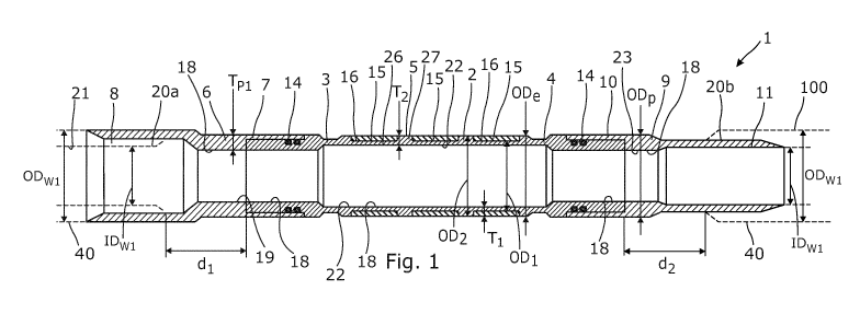
Fig. 1 shows a cross-sectional view of an annular barrier for mounting as part
of
well tubular metal structure in a small diameter borehole,
Fig. 2 shows a cross-sectional view of another annular barrier for mounting as
part of well tubular metal structure in a small diameter borehole,
Fig. 3 shows a cross-sectional view of yet another annular barrier for
mounting as
part of well tubular metal structure in a small diameter borehole, and
CA 03069881 2020-01-14
WO 2019/020729 PCT/EP2018/070249
9
Fig. 4 shows a well tubular metal structure having several annular barriers
for
isolating production zones from other zones.
All the figures are highly schematic and not necessarily to scale, and they
show
only those parts which are necessary in order to elucidate the invention,
other
parts being omitted or merely suggested.
Fig. 1 shows an annular barrier 1 for being mounted as part of a well tubular
metal structure 100 for providing zonal isolation in a borehole downhole for
isolating a first zone 101, e.g. producing oil or gas, from a second zone 102,
e.g.
producing water, as seen in Fig. 4. Tubular sections of the well tubular metal
structure are illustrated by dotted lines in Fig. 1. The annular barrier 1
comprises
an expandable metal sleeve 2 having a first end 3 and a second end 4 and an
outer face 5 facing the borehole. The expandable metal sleeve 2 is shown in
its
unexpanded condition, and in order to provide zonal isolation, the expandable
metal sleeve is expanded to a larger outer diameter by a hydraulic pressure
from
within to deform the expandable metal sleeve until the outer face presses
towards the wall 50 (shown in Fig. 4) of the borehole. The annular barrier 1
further comprises a first end part 6 having a first end 7 connected to the
first end
of the expandable metal sleeve and a second end 8 for being mounted as part of
the well tubular structure, and a second end part 9 having a first end 10
connected to the second end of the expandable metal sleeve and a second end
11 for being mounted as part of the well tubular structure. The first end 7 of
the
first end part 6 is connected "end to end" to the first end 3 of the
expandable
metal sleeve, so that part of the first end 7 overlaps part of the first end 3
and
the ends of the parts connect end to end. Likewise, the first end 10 of the
second
end part 9 is connected "end to end" to the second end 4 of the expandable
metal sleeve, so that they form one tubular pipe. Thus, there is no base pipe
within the expandable metal sleeve along an entire length L (shown in Fig. 3)
of
the expandable metal sleeve and the annular barrier is therefore "base-less".
The
second ends 8, 11 of the end parts are provided with an external thread (male
thread connection) 20b or an internal thread (female thread connection) 20b
for
being mounted to corresponding external or internal threads of the well
tubular
metal structure.
By providing such base-less annular barrier, the well tubular metal structure
can
be made with a substantially smaller outer diameter and fit into small
diameter
CA 03069881 2020-01-14
WO 2019/020729 PCT/EP2018/070249
wells than annular barriers with a base pipe and a surrounding sleeve. The
expandable metal sleeve has a first section 26 having a first outer diameter
0D1
and a first thickness T1, and circumferential projections 27 having a
thickness T2
which is larger than the first thickness T1 and having a second outer diameter
5 0D2 which is larger than the first outer diameter, so that when expanding
the
expandable metal sleeve, the first section bulges more radially outwards than
the
second section, resulting in the expandable metal sleeve 2 being strengthened
in
the expanded condition.
10 In small diameter wells, the expandable metal sleeve does not need to
expand as
much as in larger diameter wells/boreholes, and therefore it is possible for
the
expandable metal sleeve of the "base-less" annular barrier to maintain the
barrier function without the base pipe.
Furthermore, the circumferential projections 27 increase the strength of the
expanded expandable metal sleeve 2 when the expandable metal sleeve is not
expanded more than required in small diameter wells/boreholes, so that the
expandable metal sleeve can serve as both the base pipe and the barrier. The
expandable metal sleeve therefore forms the well tubular metal structure.
The annular barrier has an inner face 18 which is provided by the expandable
metal sleeve 2, the first end part 6 and the second end part 9 so that an
inner
face 22 of the expandable metal sleeve, an inner face 19 of the first end part
6
and an inner face 23 of the second end part 9 constitute the inner face of the
annular barrier. Thus, the inner face of expandable metal sleeve thereby forms
part of the inner face of the annular barrier and when mounted to the well
tubular metal structure forms part of the inner face of the well tubular metal
structure. Thus, the expandable metal sleeve does not overlap a tubular metal
part when seen in cross-section along the longitudinal extension of the well
tubular metal structure and thus does not overlap any tubular section of the
well
tubular metal structure nor the end parts in the entire thickness or length of
the
expandable metal sleeve. Therefore, the first end part, the second end part
and
the expandable metal sleeve form one tubular pipe configured to be mounted as
one part of the well tubular metal structure between other two tubular
sections of
the well tubular metal structure. Thus, the expandable metal sleeve is
arranged
in a non-overlapping configuration with the end parts in an entire thickness
and/or length of the expandable metal sleeve, and also in a non-overlapping
CA 03069881 2020-01-14
WO 2019/020729 PCT/EP2018/070249
11
configuration with other sections of the annular barrier. The first and second
end
parts and the expandable metal sleeve are mounted in succession of each other
in succession with the other tubular sections mounted together to form the
well
tubular metal structure.
As can be seen in Fig. 4, the annular barrier 1 may be without any enclosed
space and the expansion and setting of the annular barrier may occur without
the
use of ejecting pressured fluid into such annular space known from known
annular barriers. The expandable metal sleeve 2 is expanded by pressurising
the
inside in the annular barrier, e.g. by plugging the well tubular metal
structure
further down and pressurise from the top or isolate a section of the well
tubular
metal structure having one or more annular barriers and pressurise just that
section. The expandable metal sleeve and the first and second end parts are
connected so that the inner face of the expandable metal sleeve and the inner
faces of the first and second end parts constitute the inner face of the
annular
barrier configured to be in contact with a production fluid conveyed by the
well
tubular metal structure when production is initiated.
In Fig. 1, the second end 8 of the first end part 6 is provided with a female
thread connection, i.e. an internal thread 20b, and the second end 11 of the
second end part 9 is provided with a male thread connection, i.e. an external
thread 20a. When submerging the annular barrier 1 as part of the well tubular
metal structure 100, the female thread part, i.e. the female thread connection
20a, is most often the thread being closest to the top. The first and second
end
parts 6, 9 are connected to the first and second ends 3, 4 of the expandable
metal sleeve 2 by means of a standard connection 14, such as a stub acme
thread connection as shown. The first and second ends 3, 4 of the expandable
metal sleeve 2 are provided with external threads matching internal threads of
the first end part and the second end part 9, the internal and external
threads
forming the stub acme thread connections. Other standard connections within
the
oil industry can be used. Sealing elements 15 are arranged in grooves 16 on
the
outer face of the expandable metal sleeve 2 for increasing the sealing ability
to
the wall of the borehole when expanded downhole. The grooves 16 may be
provided by the circumferential projections 27, and when expanding the
expandable metal sleeve, the first section between the projections bulges more
radially outwards than the projections, forcing the sealing element radially
outwards. The expandable metal sleeve 2 has an outer sleeve diameter Ode in an
CA 03069881 2020-01-14
WO 2019/020729 PCT/EP2018/070249
12
unexpanded state, the unexpanded outer sleeve diameter being equal to or
sligthly smaller than an outer diameter OD p of the first and second end
parts, so
that the end parts protect the sealing elements while run in hole (RIH). The
expandable metal sleeve of Figs. 1 and 2 only has three grooves each having
one
sealing element. In another embodiment, the expandable metal sleeve has more
than 3 grooves with sealing elements, e.g. 5-10 grooves.
In Fig. 1, the well tubular metal structure 100 has a first inner diameter
IDwi and
a first outer diameter ODwi, and in Fig. 2 the well tubular metal structure
100
has a second outer diameter ODw2 which is smaller than the first outer
diameter.
If during running the well tubular metal structure in the small diameter
borehole,
circulation of fluid is poor due to an unexpected narrowing of the borehole,
the
well tubular metal structure can then be retracted, and part of a plurality of
tubular sections of the well tubular metal structure can be dismounted and
replaced with tubular sections having a smaller outer diameter ODw2, as shown
in
Fig. 2. This can easily be performed by replacing the first and second end
parts 6,
9 of the annular barrier 1 with other first and second end parts of a smaller
outer
diameter at the thread connections, and mounting other tubular sections having
a smaller outer diameter. Thus, by having disconnectable end parts 6, 9 of the
annular barrier, the end parts 6, 9 can easily be replaced with other end
parts
matching smaller (or larger) outer diameter tubular sections, so that reducing
the
outer diameter of the well tubular metal structure at certain sections to
increase
circulation in a certain area is possible. When designing the well, the
planner can
not foresee every incident occurring during drilling and subsequent
operations,
and therefore the planner often plans to have more than one diameter
casing/well tubular metal structure ready for completion but some components,
such as annular barriers, are more expensive than just tubular pipe/sections
and
by the present invention, the annular barriers can fit tubular pipe sections
having
different diameter and thus the annular barrier can be mounted to fit the
different casings the planner plans to have ready when completing just by
changing the end parts.
As shown in Fig. 2, the first and second end parts 6, 9 are tubular and have a
maximum wall thickness Tp1 which is larger than a maximum wall thickness T2 of
the expandable metal sleeve 2. The expandable metal sleeve is made of a
material which is more pliant than the material of the first and second end
parts.
In order to determine if the material of the expandable metal sleeve is more
CA 03069881 2020-01-14
WO 2019/020729 PCT/EP2018/070249
13
pliant and thus easier to elongate than the material of the first and second
end
parts, the test standard ASTM D1457 can be used.
In Fig. 3, the annular barrier 1 further comprises a split ring-shaped
retaining
element 17 forming a back-up for the sealing element 15. The split ring-shaped
retaining element 17 has more than one winding, so that when the expandable
tubular is expanded from the first outer diameter to the second outer
diameter,
the split ring-shaped retaining element partly unwinds. Thus, the split ring-
shaped retaining element 17 may be arranged in an abutting manner to the
sealing element, or an intermediate element 31 is arranged between the split
ring-shaped retaining element 17 and the sealing element 15.
In Figs. 1 and 2, the expandable metal sleeve 2 is connected to the end parts
6,
9 without any welded connections; however, in Fig. 3 the expandable metal
sleeve 2 is welded to the first and second end parts 6, 9, and a connection
ring
29 is arranged outside and overlapping the end 3, 4 of the expandable metal
sleeve and the first end 7, 10 of the end part 6, 9 and is threadingly
connected
thereto.
As shown in Fig. 4, the well tubular metal structure 100 may have a plurality
of
tubular sections 40 arranged with one or more tubular sections 40 between two
annular barriers 1, and the first and second end parts 6, 9 and the expandable
metal sleeve 2 are mounted in succession with the plurality of tubular
sections,
so that the first end part 6 and the second end part 9 are arranged between
the
expandable metal sleeve 2 and the tubular sections along an axial extension 30
of the well tubular metal structure 100. The expandable metal sleeve 2, the
end
parts 6, 9 and the tubular sections 40 form one single walled pipe/tubular.
Thus,
an inner face 22 (shown in Figs. 1-3) of the expandable metal sleeve 2 forms
part of the inner face 21 (shown in Figs. 1-3) of the well tubular metal
structure.
A flow section 60 is furthermore arranged between two annular barriers in the
first zone. The flow section provides primary flow into the well tubular metal
structure, when the annular barriers have been expanded (as shown in Fig. 4),
but may also be used for ejecting fluid into the annulus, e.g. for fracking
the
formation surrounding the well tubular metal structure 100.
As shown in Figs. 1 and 2, the first end part creates a first distance d1
between
the expandable metal sleeve and one of the pluralities of tubular sections,
and
CA 03069881 2020-01-14
WO 2019/020729 PCT/EP2018/070249
14
the second end part creates a second distance d2 between the expandable metal
sleeve and another one of the plurality of tubular sections. Thus, the
expandable
metal sleeve does not overlap any of the plurality of tubular sections.
The expandable metal sleeves are expanded by an internal fluid pressure in the
well tubular metal structure. In order to provide an internal pressure, the
entire
well tubular metal structure may be pressurised from within, or an expansion
tool
for isolating a part of the well tubular metal structure opposite the
expandable
metal sleeve may be introduced in the well tubular metal structure for
pressurising that part and expand the expandable metal sleeves one by one. The
well tubular metal structure may be submerged by means of a drill pipe, and
the
annular barriers may be expanded by pressuring the drill pipe and the well
tubular metal structure before disconnecting the drill pipe from the well
tubular
metal structure.
Even though not shown, at least one of the tubular sections between the
annular
barriers may comprise an inflow section for letting fluid into the well
tubular
metal structure also called the production casing. One of the tubular sections
may also comprise a sensor section for measuring a condition downhole, e.g.
for
controlling and optimising the production. One of the tubular sections further
up
the well may also comprise a gas lift valve for introducing gas to reduce the
hydrostatic pressure in the fluid column.
The well tubular metal structure may be a production casing installed more
permanently in the borehole, or the well tubular metal structure may be a
velocity string used for early production. In the event that the early
production
shows a successful result, the velocity string is then used as the production
casing.
By fluid or well fluid is meant any kind of fluid that may be present in oil
or gas
wells downhole, such as natural gas, oil, oil mud, crude oil, water, etc. By
gas is
meant any kind of gas composition present in a well, completion, or open hole,
and by oil is meant any kind of oil composition, such as crude oil, an oil-
containing fluid, etc. Gas, oil, and water fluids may thus all comprise other
elements or substances than gas, oil, and/or water, respectively.
CA 03069881 2020-01-14
WO 2019/020729 PCT/EP2018/070249
By a well tubular metal structure or casing is meant any kind of pipe, tubing,
tubular, liner, string etc. used downhole in relation to oil or natural gas
production.
5 In the event that the tool is not submergible all the way into the
casing, a
downhole tractor can be used to push the tool all the way into position in the
well. The downhole tractor may have projectable arms having wheels, wherein
the wheels contact the inner surface of the casing for propelling the tractor
and
the tool forward in the casing. A downhole tractor is any kind of driving tool
10 capable of pushing or pulling tools in a well downhole, such as a Well
Tractor .
Although the invention has been described in the above in connection with
preferred embodiments of the invention, it will be evident for a person
skilled in
the art that several modifications are conceivable without departing from the
15 invention as defined by the following claims.